Advertisement
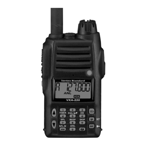
Air Band Transceiver
VXA-220
Service Manual
©
2006 VERTEX STANDARD CO., LTD.
This transceiver was assembled using Pb (lead) free solder, based on the RoHS specification.
Only lead-free solder (Alloy Composition: Sn-3.0Ag-0.5Cu) should be used for repairs performed on this
apparatus. The solder stated above utilizes the alloy composition required for compliance with the lead-free
specification, and any solder with the above alloy composition may be used.
Specifications ............................................................................................................................................................... 2
Exploded View & Miscellaneous Parts .................................................................................................................. 3
Block Diagram ............................................................................................................................................................. 5
Circuit Description ..................................................................................................................................................... 7
Alignment ..................................................................................................................................................................... 9
MAIN Unit Circuit Diagram .................................................................................................................................. 13
MAIN Unit Parts Layout ......................................................................................................................................... 15
MAIN Unit Parts List ............................................................................................................................................... 17
(EC072N90A)
Introduction
This manual provides technical information necessary for servicing the VXA-
220 Air Band Transceiver.
Servicing this equipment requires expertise in handling surface-mount chip
components. Attempts by non-qualified persons to service this equipment may
result in permanent damage not covered by the warranty, and may be illegal
in some countries.
Two PCB layout diagrams are provided for each double-sided circuit board in
the transceiver. Each side of thr board is referred to by the type of the majority
of components installed on that side ("leaded" or "chip-only"). In most cases
one side has only chip components, and the other has either a mixture of both
chip and leaded components (trimmers, coils, electrolytic capacitors, ICs, etc.),
or leaded components only.
While we believe the technical information in this manual to be correct, Vertex
Standard assumes no liability for damage that may occur as a result of typo-
graphical or other errors that may be present. Your cooperation in pointing
out any inconsistencies in the technical information would be appreciated.
Important Note
Contents
VERTEX STANDARD CO., LTD.
4-8-8 Nakameguro, Meguro-Ku, Tokyo 153-8644, Japan
VERTEX STANDARD
US Headquarters
10900 Walker Street, Cypress, CA 90630, U.S.A.
YAESU EUROPE B.V.
P.O. Box 75525, 1118 ZN Schiphol, The Netherlands
YAESU UK LTD.
Unit 12, Sun Valley Business Park, Winnall Close
Winchester, Hampshire, SO23 0LB, U.K.
VERTEX STANDARD HK LTD.
Unit 5, 20/F., Seaview Centre, 139-141 Hoi Bun Road,
Kwun Tong, Kowloon, Hong Kong
VERTEX STANDARD ( AUSTRALIA ) PTY., LTD.
Normanby Business Park, Unit 14/45 Normanby Road
Notting Hill 3168, Victoria, Australia
1
Advertisement
Table of Contents

Related Manuals for Vertex Standard VXA-200


Summary of Contents for Vertex Standard VXA-200
-
Page 1: Table Of Contents
VERTEX STANDARD HK LTD. Service Manual Unit 5, 20/F., Seaview Centre, 139-141 Hoi Bun Road, Kwun Tong, Kowloon, Hong Kong VERTEX STANDARD ( AUSTRALIA ) PTY., LTD. Normanby Business Park, Unit 14/45 Normanby Road © 2006 VERTEX STANDARD CO., LTD. -
Page 2: Specifications
Specifications General Frequency Range: 118.000 - 136.975 MHz, 108.000 - 136.975 MHz, Weather Channels (WX-01 - WX-10: USA version only) Channel Spacing: 25 kHz Emission Type: TX: AM, RX: AM & FM (FM: for receiving the Weather Channels, USA version only) Supply Voltage: 6.0 - 15.0 VDC Current Consumption (approx.):... -
Page 3: Exploded View & Miscellaneous Parts
Exploded View & Miscellaneous Parts RA0882500 WINDOW RA0869100 RA0786600 EXT CAP DOUBLE FACE (WINDOW) CP8817001 CP8817001 FRONT PANEL ASSY FRONT PANEL ASSY RA0777100 RA0776700 SPECIAL NUT (VOL) HOLDER (PTT) RA0768800 O RING RA0776850A RUBBER KNOB (PTT) RA0869000 KNOB (ENC) RA040160A RA0787000 RA0866300 O RING... - Page 4 Exploded View & Miscellaneous Parts...
-
Page 5: Block Diagram
Block Diagram... - Page 6 Block Diagram Note...
-
Page 7: Circuit Description
Circuit Description DC is applied to the ANL MUTE gate Q1022 (UMG2N), Receive Signal Path thus reducing the pulse noises. Incoming RF from the antenna jack is passed through a low-pass filter and high-pass filter consisting of coils The processed audio signal from Q1019-1 (LM2902PWR) L1024, L1027, L1028, L1029, L1030 &... -
Page 8: Transmit Inhibit
Circuit Description transmit signal then passes through the antenna switch serial dividing data from the microprocessor Q1015 D1038 (RLS135), and is low-pass filtered to suppress (LC87F7BC8A), which causes the pre-divided VCO sig- away harmonic spurious radiation before delivery to the nal to be further divided in the programmable divider antenna. -
Page 9: Alignment
Whenev- Vertex Standard reserves the right to change circuits and er possible, alignments should be made with oscillator alignment procedures, in the interest of improved perfor- shields and circuit boards firmly affixed in place. - Page 10 Alignment PLL Section Transmitter Section PLL Reference Frequency AM TX Power Adjustment Connect the wattmeter, dummy load and frequency Connect the wattmeter and dummy load to the an- counter to the antenna jack, then set the transceiver to tenna jack, then set the transceiver to 128.000 MHz 128.000 MHz and turn the transceiver off.
- Page 11 Alignment Receiver Section AM Squelch Hysteresis Adjustment AM Squelch Tight Adjustment Press and hold in the PTT switch, MONITOR switch, Connect the Radio Tester to the antenna jack, then and [ ENT ( )] key while turning the transceiver on adjust the output level to +10 dBμ...
- Page 12 Alignment...
-
Page 13: Main Unit Circuit Diagram
MAIN Unit Circuit Diagram RX: 4.85 V 1.76 V RX: 4.65 V RX: 3.59 V RX: 2.49 V RX: 2.95 V 1.76 V TX: 1.88 V TX: 3.73 V TX: 2.49 V TX: 4.78 V TX: 3.06 V 1.26 V 1.75 V 1.76 V RX: 3.58 V... - Page 14 MAIN Unit Note...
-
Page 15: Main Unit Parts Layout
MAIN Unit Parts Layout (Side A) AN6123MS LM2902PWR 2SA1774 (FR) DTC144EE (26) UMD5N DAN222 (N) (Q1011) (Q1005) (Q1013) (Q1004) (Q1046) (D1005) LC87F7BC8A TDA2822D 2SC4417 (BR) CPH6102 (AB) RD07MVS1 UMG2N (Gc) HSM88WA (Q1015) (Q1003) (Q1006, 1048, 1050) (Q1002) (Q1045) (Q1014) (D1041) -
Page 16: Main Unit Parts Layout
MAIN Unit Parts Layout (Side B) MB15A01PFV1 LM2902PWR AK93C95AF 2SC4617 (BR) 3SK318 (YB) CPH6102 (AB) S-812C35AUA DTA114TE (14) DTC143ZE (E23) UMD5N UMW1 (W1) DAN222 (N) (Q1025) (Q1019) (Q1008) (Q1012, 1017, (Q1043, 1049) (Q1007, 1031, 1038, (Q1033) (Q1021) (Q1053) (Q1016, 1026, (Q1030) (D1026) 1020, 1024) -
Page 17: Main Unit Parts List
MAIN Unit Parts List DESCRIPTION VALUE TOL. MFR'S DESIG VXSTD P/N VERS. LOT SIDE LAY ADR PCB with Components CB3729001 DST: VTX CB3729002 DST: EXP Printed Circuit Board AC072N000 FR0155000 C 1001 CHIP CAP. 0.001uF GRM155B11H102KA01D K22178809 C 1002 CHIP CAP. 0.01uF GRM36B103K16PT K22128804... -
Page 18: Parts List
MAIN Unit Parts List DESCRIPTION VALUE TOL. MFR'S DESIG VXSTD P/N VERS. LOT SIDE LAY ADR C 1073 CHIP CAP. 0.01uF GRM36B103K16PT K22128804 C 1074 CHIP CAP. 0.001uF GRM155B11H102KA01D K22178809 C 1078 CHIP CAP. 0.001uF GRM155B11H102KA01D K22178809 C 1079 CHIP CAP. 6.3V GRM155B30J105KE18D K22088803... - Page 19 MAIN Unit Parts List DESCRIPTION VALUE TOL. MFR'S DESIG VXSTD P/N VERS. LOT SIDE LAY ADR C 1158 CHIP CAP. 0.001uF GRM155B11H102KA01D K22178809 C 1159 CHIP CAP. 39pF GRM1552C1H390JZ01D K22178226 C 1160 CHIP CAP. 0.001uF GRM155B11H102KA01D K22178809 C 1161 CHIP CAP. 0.001uF GRM155B11H102KA01D K22178809...
- Page 20 MAIN Unit Parts List DESCRIPTION VALUE TOL. MFR'S DESIG VXSTD P/N VERS. LOT SIDE LAY ADR C 1237 CHIP CAP. 0.001uF GRM155B11H102KA01D K22178809 C 1238 CHIP CAP. 0.001uF GRM155B11H102KA01D K22178809 C 1239 CHIP CAP. 0.01uF GRM36B103K16PT K22128804 C 1240 CHIP CAP. 0.01uF GRM36B103K16PT K22128804...
- Page 21 Q 1031 TRANSISTOR CPH6102-TL G3070223 Q 1032 TRANSISTOR 2SC5555ZD-TR G3355557 Q 1033 S-812C35AUA-C2P-T2G G1093672 Q 1034 TRANSISTOR 2SC5555ZD-TR G3355557 Q 1035 TRANSISTOR UMD5N TR G3070343 Q 1037 TRANSISTOR 2SC4915-O(TE85L.F) G3349158O Q 1038 TRANSISTOR CPH6202-TL G3070265 : Please contact Vertex Standard...
- Page 22 MAIN Unit Parts List DESCRIPTION VALUE TOL. MFR'S DESIG VXSTD P/N VERS. LOT SIDE LAY ADR Q 1039 TK10931VTL-G G1093013 Q 1040 TRANSISTOR 2SC5226-5-TL G3352268E Q 1041 TRANSISTOR CPH6202-TL G3070265 Q 1042 TRANSISTOR 2SC4915-O(TE85L.F) G3349158O Q 1043 3SK318 TL G4803188 Q 1044 RD01MUS1(TAPE) G3070321...
- Page 23 MAIN Unit Parts List DESCRIPTION VALUE TOL. MFR'S DESIG VXSTD P/N VERS. LOT SIDE LAY ADR R 1058 CHIP RES. 1/16W RMC1/16S 103JTH J24189037 R 1059 CHIP RES. 1/16W RMC1/16S 223JTH J24189041 R 1060 CHIP RES. 1/16W RMC1/16S 473JTH J24189045 R 1061 CHIP RES.
- Page 24 MAIN Unit Parts List DESCRIPTION VALUE TOL. MFR'S DESIG VXSTD P/N VERS. LOT SIDE LAY ADR R 1135 CHIP RES. 1.2k 1/16W RMC1/16S 122JTH J24189026 R 1136 CHIP RES. 330k 1/16W RMC1/16S 334JTH J24189055 R 1137 CHIP RES. 1/16W RMC1/16S 183JTH J24189040 R 1138 CHIP RES.
- Page 25 MAIN Unit Parts List DESCRIPTION VALUE TOL. MFR'S DESIG VXSTD P/N VERS. LOT SIDE LAY ADR R 1212 CHIP RES. 100k 1/16W RMC1/16S 104JTH J24189049 R 1214 CHIP RES. 1/16W RMC1/16S 102JTH J24189025 R 1215 CHIP RES. 220k 1/16W RMC1/16S 224JTH J24189053 R 1216 CHIP RES.
- Page 26 MAIN Unit Parts List DESCRIPTION VALUE TOL. MFR'S DESIG VXSTD P/N VERS. LOT SIDE LAY ADR LIGHT GUIDE (LCD) RA0778100 LCD HOLDER RA077820A TERMINAL HOLDER RA010340B TERMINAL PLATE (+IS) RA0723400 PORON SHEET RA0844200...
- Page 28 Copyright 2006 VERTEX STANDARD CO., LTD. All rights reserved No portion of this manual may be reproduced without the permission of VERTEX STANDARD CO., LTD.
Need help?
Do you have a question about the VXA-200 and is the answer not in the manual?
Questions and answers