Vertex Standard VXA-300 Service Manual
Air band transceiver
Hide thumbs
Also See for VXA-300:
- Operating manual (60 pages) ,
- Brochure (2 pages) ,
- Operating manual (60 pages)
Table of Contents
Advertisement
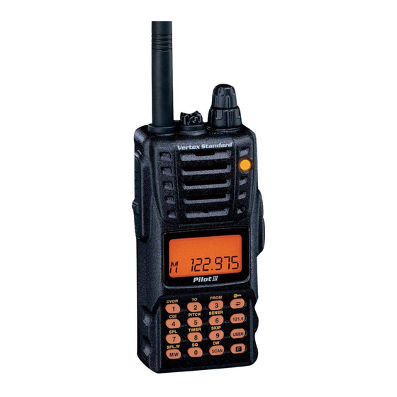
Air Band Transceiver
VXA-300
Service Manual
©
2004 VERTEX STANDARD CO., LTD.
Specifications ............................................................................................................................................................... 2
Exploded View & Miscellaneous Parts .................................................................................................................. 3
Block Diagram ............................................................................................................................................................. 5
Circuit Description ..................................................................................................................................................... 7
Alignment ................................................................................................................................................................... 11
MAIN Unit Circuit Diagram ................................................................................................................................... 15
MAIN Unit Parts Layout .......................................................................................................................................... 17
MAIN Unit Parts List ............................................................................................................................................... 19
(EC057N90A)
This manual provides technical information necessary for
servicing the VXA-300 Air Band Transceiver.
Servicing this equipment requires expertise in handling sur-
face-mount chip components. Attempts by non-qualified
persons to service this equipment may result in permanent
damage not covered by the warranty, and may be illegal in
some countries.
Two PCB layout diagrams are provided for each double-
sided circuit board in the transceiver. Each side of thr board
is referred to by the type of the majority of components
installed on that side ("leaded" or "chip-only"). In most
cases one side has only chip components, and the other has
either a mixture of both chip and leaded components (trim-
mers, coils, electrolytic capacitors, ICs, etc.), or leaded com-
ponents only.
While we believe the technical information in this manual
to be correct, Vertex Standard assumes no liability for dam-
age that may occur as a result of typographical or other
errors that may be present. Your cooperation in pointing
out any inconsistencies in the technical information would
be appreciated.
Contents
VERTEX STANDARD CO., LTD.
4-8-8 Nakameguro, Meguro-Ku, Tokyo 153-8644, Japan
VERTEX STANDARD
US Headquarters
10900 Walker Street, Cypress, CA 90630, U.S.A.
YAESU EUROPE B.V.
P.O. Box 75525, 1118 ZN Schiphol, The Netherlands
YAESU UK LTD.
Unit 12, Sun Valley Business Park, Winnall Close
Winchester, Hampshire, SO23 0LB, U.K.
VERTEX STANDARD HK LTD.
Unit 5, 20/F., Seaview Centre, 139-141 Hoi Bun Road,
Kwun Tong, Kowloon, Hong Kong
1
Advertisement
Table of Contents

Related Manuals for Vertex Standard VXA-300


Summary of Contents for Vertex Standard VXA-300
-
Page 1: Table Of Contents
While we believe the technical information in this manual to be correct, Vertex Standard assumes no liability for dam- age that may occur as a result of typographical or other errors that may be present. Your cooperation in pointing out any inconsistencies in the technical information would be appreciated. -
Page 2: Specifications
Specifications General Frequency Range: 118.000 - 136.975 MHz 108.000 - 136.975 MHz, Weather Channels (WX-01 - WX-10: USA version only) Channel Spacing: 25 kHz/8.33 kHz (8.33 kHz: RX only) Emission Type: TX: AM RX: AM & FM (FM: for receiving the Weather Channels, USA version only) Supply Voltage: 6.0 - 15.0 VDC Current Consumption (approx.): 20 µA (power off),... -
Page 3: Exploded View & Miscellaneous Parts
Exploded View & Miscellaneous Parts RA0576800 RA0304300 WINDOW WASHER RA0576900 DOUBLE FACE RA0577600 EXT CAP RA0591700 PANEL ASSY RA0578400 RING NUT RA0576700 PANEL RA0478500 SPECIAL NUT ASSY RA0577100 HOLDER RA0467600 RA0577000 O RING RUBBER KNOB RA0577800 RA0292100 KNOB SHEET RA0577700 KNOB RA0577500... - Page 4 Exploded View & Miscellaneous Parts...
-
Page 5: Block Diagram
Block Diagram... - Page 6 Block Diagram...
-
Page 7: Circuit Description
Circuit Description In the AM mode, detected audio from Q1058 Receive Signal Path (TK10931VT1) is passed through the audio amplifier Incoming RF from the antenna jack is passed through a Q1037-1 (NJM12904R) and ANL circuit, then applied to low-pass filter and high-pass filter consisting of coils the AF amplifier Q1037-2 (NJM12904R). -
Page 8: Transmit Inhibit
Circuit Description Transmit Signal Path PLL Frequency Synthesizer Speech input from the microphone is passed through the PLL circuitry consists of VCO Q1046 (2SC5555ZD), VCO microphone amplifier Q1011-1 (NJM12902V), then ap- buffer Q1049 & Q1051(both 2SC5555ZD), and PLL sub- plied to the ALC amplifier Q1017 (AN6123MS). The am- system IC Q1041 (MB15A01PFV1), which contains a ref- plified speech signal is passed through the high-pass fil- erence divider, serial-to-parallel data latch, programma-... - Page 9 Circuit Description For transmission, the VCO Q1046 (2SC5555ZD) oscillates Push-To-Talk Transmit Activation between 118 and 137 MHz. The remainder of the PLL cir- The PTT switch on the microphone is control to pin 22 of cuitry is shared with the receiver. However, the dividing microprocessor Q1024 (LC87F74C8A), so that when the data from the microprocessor is such that the VCO fre- PTT switch is closed, pin 31 of Q1024 (LC87F74C8A) goes...
- Page 10 Circuit Description Note...
-
Page 11: Alignment
Alignment Introduction Required Test Equipment The VXA-300 is carefully aligned at the factory for the Avionics Radio Tester with calibrated output level at specified performance across the Aircraft and Weather 200 MHz bands. Realignment should therefore not be necessary In-line Wattmeter with 5 % accuracy at 200 MHz except in the event of a component failure. - Page 12 Weather channel mode. The left. VXA-300 will scan quickly through the Weather Recall the memory channel into which you just stored channels. Weather Channel ”WX-010” in the previous step, then Press the MONITOR switch momentarily to stop turn the radio off.
- Page 13 Alignment Transmitter Section FM Squelch Tight Adjustment Connect the Radio Tester to the antenna jack, then TX Power Adjustment adjust the output level to +10 dBµV (with a standard Connect the wattmeter and dummy load to the an- FM modulation: ±3kHz deviation @ 1 kHz) at 163.275 tenna jack, then set the transceiver to 128.000 MHz MHz.
-
Page 14: Resetting The Cpu
Alignment VOR Section VOR Angle Adjustment Connect the Avionics Radio Tester to the antenna jack. VOR Sensitivity Adjustment Set the transceiver to 108.000 MHz, set up the “FROM” Connect the Radio Tester to the antenna jack, then ad- mode (press [ F ] + [ 3 ( FROM )] key, if necessary), and just the output level to +5 dBµV (with a standard AM set the Avionics Radio Tester as shown below. -
Page 15: Main Unit Circuit Diagram
MAIN Unit Circuit Diagram RX: 3.6 V RX: 2.9 V TX: 3.1 V TX: 3.7 V RX: 4.8 V 1.8 V TX: 2.0 V 1.3 V 1.8 V 1.8 V 1.8 V RX: 2.5 V TX: 2.6 V RX: 3.5 V TX: 3.7 V RX: 0.2 V TX: 4.8 V... - Page 16 MAIN Unit Note...
-
Page 17: Main Unit Parts Layout
MAIN Unit Parts Layout (Side A) LC87F74C8A (Q1024) 2SB1201S (Q1014) NJM12804V (Q1021) BU4094BCFV (Q1025) NJM12902V (Q1020) RD08MVS1 CPH6102 (AB) DTA143EE (13) DTC143ZE (E23) DTC144EE (26) HN1J02FU (KS) UMG2N (G2) DA221 (K) HSM88WA (K) (Q1069) (Q1008) (Q1073) (Q1015) (Q1070) (Q1018, 1023, (Q1019) (D1006, 1008) (D1043) -
Page 18: Main Unit
MAIN Unit Parts Layout (Side B) M62364FP (Q1045) TK10931 (Q1058) MB15A01PFV1 BU4094BCFV (Q1041) (Q1027) NJM12902V (Q1011, 1071) NJM2901V (Q1065) NJM12804V 2SC4617 (BR) 2SK2170 (JA) AN6123MS CPH6102 (AB) DTA143EE (13) DTC124TE (05) NJM2125F DA221 (K) DAN222 (N) UMP11N (P11) AK93C95AF DTC144EE (26) (Q1010) (Q1037, 1072) (Q1009, 1013,... -
Page 19: Main Unit Parts List
MAIN Unit Parts List DESCRIPTION VALUE TOL. MFR'S DESIG VXSTD P/N VERS. LOT SIDE LAY ADR PCB with Components CB2638001 DST: VTX CB2638002 DST: EXP Printed Circuit Board AC057N000 FR011210C C 1001 CHIP CAP. 0.001uF GRM36B102K50PT K22178809 C 1002 CHIP CAP. 0.01uF GRM36B103K16PT K22128804... -
Page 20: Parts List
MAIN Unit Parts List DESCRIPTION VALUE TOL. MFR'S DESIG VXSTD P/N VERS. LOT SIDE LAY ADR C 1077 CHIP CAP. 0.22uF GRM39B224K10PT K22104801 C 1078 CHIP CAP. 0.0039uF GRM36B392K50PT K22178816 C 1079 CHIP CAP. 0.0033uF GRM36B332K50PT K22178815 C 1080 CHIP CAP. 0.1uF GRM36B104K10PT K22108802... - Page 21 MAIN Unit Parts List DESCRIPTION VALUE TOL. MFR'S DESIG VXSTD P/N VERS. LOT SIDE LAY ADR C 1156 CHIP CAP. 0.1uF GRM36B104K10PT K22108802 C 1157 CHIP CAP. 0.001uF GRM36B102K50PT K22178809 C 1158 CHIP CAP. 0.1uF GRM36B104K10PT K22108802 C 1159 CHIP CAP. 0.001uF GRM36B102K50PT K22178809...
- Page 22 MAIN Unit Parts List DESCRIPTION VALUE TOL. MFR'S DESIG VXSTD P/N VERS. LOT SIDE LAY ADR C 1232 CHIP TA.CAP. 10uF TEMSVA1A106M-8R K78100028 C 1233 CHIP CAP. 39pF GRM36CH390J50PT K22178226 C 1234 CHIP CAP. 0.5pF GRM36CK0R5C50PT K22178201 C 1236 CHIP CAP. 27pF GRM36CH270J50PT K22178222...
- Page 23 MAIN Unit Parts List DESCRIPTION VALUE TOL. MFR'S DESIG VXSTD P/N VERS. LOT SIDE LAY ADR C 1306 CHIP CAP. 470pF GRM36B471K50PT K22178805 C 1307 CHIP CAP. 470pF GRM36B471K50PT K22178805 C 1308 CHIP CAP. 0.001uF GRM36B102K50PT K22178809 C 1309 CHIP TA.CAP. TEMSVA1V105M-8R K78160032 CD1001 CERAMIC DISC...
- Page 24 TRANSISTOR DTC144EE TL G3070075 Q 1045 M62364FP 600D G1093033 Q 1046 TRANSISTOR 2SC5555ZD-TR G3355557 Q 1047 TRANSISTOR DTA143EE TL G3070252 Q 1048 S-812C35AUA-C2P-T2 G1093672 Q 1049 TRANSISTOR 2SC5555ZD-TR G3355557 Q 1050 TRANSISTOR UMA5N TR G3070138 : Please contact Vertex Standard...
- Page 25 MAIN Unit Parts List DESCRIPTION VALUE TOL. MFR'S DESIG VXSTD P/N VERS. LOT SIDE LAY ADR Q 1051 TRANSISTOR 2SC5555ZD-TR G3355557 Q 1052 2SK2170-TL G3821708 Q 1053 TRANSISTOR DTC144EE TL G3070075 Q 1054 TRANSISTOR 2SC4617 TL R G3346178R Q 1055 TRANSISTOR DTA143EE TL G3070252...
- Page 26 MAIN Unit Parts List DESCRIPTION VALUE TOL. MFR'S DESIG VXSTD P/N VERS. LOT SIDE LAY ADR R 1048 CHIP RES. 1/16W RMC1/16S 103JTH J24189037 R 1049 CHIP RES. 1/16W RMC1/16S 473JTH J24189045 R 1050 CHIP RES. 1/16W RMC1/16S 473JTH J24189045 R 1051 CHIP RES.
- Page 27 MAIN Unit Parts List DESCRIPTION VALUE TOL. MFR'S DESIG VXSTD P/N VERS. LOT SIDE LAY ADR R 1128 CHIP RES. 1/16W RMC1/16S 563JTH J24189046 R 1129 CHIP RES. 1/16W RMC1/16S 473JTH J24189045 R 1130 CHIP RES. 1/16W RMC1/16S 683JTH J24189047 R 1132 CHIP RES.
- Page 28 MAIN Unit Parts List DESCRIPTION VALUE TOL. MFR'S DESIG VXSTD P/N VERS. LOT SIDE LAY ADR R 1205 CHIP RES. 1/16W RMC1/16S 473JTH J24189045 R 1206 CHIP RES. 2.2k 1/16W RMC1/16S 222JTH J24189029 R 1207 CHIP RES. 1/16W RMC1/16S 105JTH J24189061 R 1208 CHIP RES.
- Page 29 MAIN Unit Parts List DESCRIPTION VALUE TOL. MFR'S DESIG VXSTD P/N VERS. LOT SIDE LAY ADR R 1278 CHIP RES. 1/16W RMC1/16S 223JTH J24189041 R 1279 CHIP RES. 220k 1/16W RMC1/16S 224JTH J24189053 R 1280 CHIP RES. 180k 1/16W RMC1/16S 184JTH J24189052 R 1281 CHIP RES.
- Page 30 MAIN Unit Parts List DESCRIPTION VALUE TOL. MFR'S DESIG VXSTD P/N VERS. LOT SIDE LAY ADR INTER CONNECTOR (LCD) RA0580700 REFLECTOR SHEET RA0580500 MIC HOLDER RUBBER RA0578200...
- Page 32 Copyright 2004 VERTEX STANDARD CO., LTD. All rights reserved No portion of this manual may be reproduced without the permission of VERTEX STANDARD CO., LTD.
Need help?
Do you have a question about the VXA-300 and is the answer not in the manual?
Questions and answers