Table of Contents
Advertisement
Scan this tag with your mobile device
to learn more about this product.
Individual carrier rates may apply.
Start by downloading the free
mobile app at http://gettag.mobi
Visit our website at
www.MillerWelds.com/ams
Auto-Axcess E Digital
Welding Power
Sources
File: Advanced Manufacturing Systems
OM-257 675D
2014−03
Processes
MIG (GMAW) Welding
Pulsed MIG (GMAW-P)
Flux Cored (FCAW) Welding
Automatic Welding
Description
Automatic Welding Interface And
Arc Welding Power Source
Advertisement
Table of Contents
Troubleshooting

Related Manuals for Miller OM-257 675D


Summary of Contents for Miller OM-257 675D
- Page 1 OM-257 675D 2014−03 Processes MIG (GMAW) Welding Pulsed MIG (GMAW-P) Flux Cored (FCAW) Welding Automatic Welding Description Automatic Welding Interface And Scan this tag with your mobile device Arc Welding Power Source to learn more about this product. Individual carrier rates may apply.
- Page 2 We know you don’t have time to do it any other way. That’s why when Niels Miller first started building arc welders in 1929, he made sure his products offered long-lasting value and superior quality.
-
Page 3: Table Of Contents
TABLE OF CONTENTS SECTION 1 − SAFETY PRECAUTIONS - READ BEFORE USING ....... . . 1-1. - Page 4 TABLE OF CONTENTS SECTION 8 − GENERAL INSTALLATION ............8-1.
- Page 5 TABLE OF CONTENTS SECTION 12 − SAFETY PRECAUTIONS FOR SERVICING ........12-1.
-
Page 7: Section 1 − Safety Precautions - Read Before Using
SECTION 1 − SAFETY PRECAUTIONS - READ BEFORE USING som 2013−09 Protect yourself and others from injury — read, follow, and save these important safety precautions and operating instructions. 1-1. Symbol Usage DANGER! − Indicates a hazardous situation which, if Indicates special instructions. - Page 8 D Remove stick electrode from holder or cut off welding wire at FUMES AND GASES can be hazardous. contact tip when not in use. D Wear body protection made from durable, flame−resistant material Welding produces fumes and gases. Breathing (leather, heavy cotton, wool). Body protection includes oil-free these fumes and gases can be hazardous to your clothing such as leather gloves, heavy shirt, cuffless trousers, high health.
-
Page 9: Additional Symbols For Installation, Operation, And Maintenance
1-3. Additional Symbols For Installation, Operation, And Maintenance FIRE OR EXPLOSION hazard. MOVING PARTS can injure. D Do not install or place unit on, over, or near D Keep away from moving parts such as fans. combustible surfaces. D Keep all doors, panels, covers, and guards D Do not install unit near flammables. -
Page 10: California Proposition 65 Warnings
1-4. California Proposition 65 Warnings Welding or cutting equipment produces fumes or gases This product contains chemicals, including lead, known to which contain chemicals known to the State of California to the state of California to cause cancer, birth defects, or other cause birth defects and, in some cases, cancer. -
Page 11: Section 2 − Consignes De Sécurité − Lire Avant Utilisation
SECTION 2 − CONSIGNES DE SÉCURITÉ − LIRE AVANT UTILISATION fre_som_2013−09 Pour écarter les risques de blessure pour vous−même et pour autrui — lire, appliquer et ranger en lieu sûr ces consignes relatives aux précautions de sécurité et au mode opératoire. 2-1. - Page 12 D Ne pas raccorder plus d’une électrode ou plus d’un câble de D Avoir recours à des écrans protecteurs ou à des rideaux pour masse à une même borne de sortie de soudage. Débrancher le protéger les autres contre les rayonnements les éblouissements câble pour le procédé...
-
Page 13: Dangers Supplémentaires En Relation Avec L'installation, Le Fonctionnement Et La Maintenance
LES BOUTEILLES peuvent exploser DES PIECES DE METAL ou DES si elles sont endommagées. SALETES peuvent provoquer des blessures dans les yeux. Les bouteilles de gaz comprimé contiennent du gaz sous haute pression. Si une bouteille est D Le soudage, l’écaillement, le passage de la endommagée, elle peut exploser. - Page 14 LES CHARGES ÉLECTROSTATI- RAYONNEMENT HAUTE QUES peuvent endommager les cir- FRÉQUENCE (H.F.) risque cuits imprimés. provoquer des interférences. D Établir la connexion avec la barrette de terre D Le rayonnement haute fréquence (H.F.) peut avant de manipuler des cartes ou des pièces. provoquer des interférences avec les équi- pements de radio−navigation et de com- D Utiliser des pochettes et des boîtes antista-...
-
Page 15: Proposition Californienne 65 Avertissements
2-4. Proposition californienne 65 Avertissements Les équipements de soudage et de coupage produisent des Ce produit contient des produits chimiques, notamment du fumées et des gaz qui contiennent des produits chimiques plomb, dont l’État de Californie reconnaît qu’ils provoquent dont l’État de Californie reconnaît qu’ils provoquent des mal- des cancers, des malformations congénitales ou d’autres formations congénitales et, dans certains cas, des cancers. - Page 16 OM-257 675 Page 10...
-
Page 17: Section 3 − Definitions
SECTION 3 − DEFINITIONS 3-1. Additional Safety Symbols And Definitions Some symbols are found only on CE products. Warning! Watch Out! There are possible hazards as shown by the symbols. Safe1 2012−05 When power is applied failed parts can explode or cause other parts to explode. Safe26 2012−05 L1 L2 Always connect green, Or greenwith yellow stripe, wire to supply grounding terminal. - Page 18 Notes OM-257 675 Page 12...
-
Page 19: Section 4 − Specifications For Auto-Axcess E 300 Digital
SECTION 4 − SPECIFICATIONS FOR AUTO-AXCESS E 300 DIGITAL 4-1. Serial Number And Rating Label Location The serial number and rating information for this product is located on the front. Use rating label to determine input power requirements and/or rated output. -
Page 20: Duty Cycle And Overheating
4-5. Duty Cycle And Overheating Duty Cycle is percentage of 10 minutes that unit can weld at rated load without overheating. If unit overheats, thermostat(s) opens, output stops, and cooling fan runs. Wait fifteen minutes for unit to cool. Reduce amperage or duty cycle before welding. -
Page 21: Electrical Service Guide
4-7. Electrical Service Guide Elec Serv 2014−01 Failure to follow these electrical service guide recommendations could create an electric shock or fire hazard. These recommendations are for a dedicated branch circuit sized for the rated output and duty cycle of the welding power source. NOTICE −... - Page 22 Notes OM-257 675 Page 16...
-
Page 23: Section 5 − Specifications For Auto-Axcess E 450 Digital
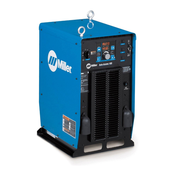
SECTION 5 − SPECIFICATIONS FOR AUTO-AXCESS E 450 DIGITAL Appearance of actual unit may vary from unit shown in manual. 5-1. Serial Number And Rating Label Location The serial number and rating information for this product is located on the front. Use rating label to determine input power requirements and/or rated output. -
Page 24: Duty Cycle And Overheating
5-5. Duty Cycle And Overheating Duty Cycle is percentage of 10 minutes that unit can weld at rated load without overheating. If unit overheats, thermostat(s) opens, output stops, and cooling fan runs. Wait fifteen minutes for unit to cool. Reduce amperage or duty cycle before welding. -
Page 25: Electrical Service Guide
5-7. Electrical Service Guide Elec Serv 2014−01 Failure to follow these electrical service guide recommendations could create an electric shock or fire hazard. These recommendations are for a dedicated branch circuit sized for the rated output and duty cycle of the welding power source. NOTICE −... - Page 26 Notes OM-257 675 Page 20...
-
Page 27: Section 6 − Specifications For Auto-Axcess E 675 Digital
SECTION 6 − SPECIFICATIONS FOR AUTO-AXCESS E 675 DIGITAL Appearance of actual unit may vary from unit shown in manual. 6-1. Serial Number And Rating Label Location The serial number and rating information for this product is located on the front. Use rating label to determine input power requirements and/or rated output. -
Page 28: Duty Cycle And Overheating
6-5. Duty Cycle And Overheating Duty Cycle is percentage of 10 minutes that unit can weld at rated load without overheating. If unit overheats, thermostat(s) opens, output stops, and cooling fan runs. Wait fifteen minutes for unit to cool. Reduce amperage or duty cycle before welding. -
Page 29: Electrical Service Guide
6-7. Electrical Service Guide Elec Serv 2014−01 Failure to follow these electrical service guide recommendations could create an electric shock or fire hazard. These recommendations are for a dedicated branch circuit sized for the rated output and duty cycle of the welding power source. NOTICE −... - Page 30 Notes OM-257 675 Page 24...
-
Page 31: Section 7 − License Agreement
SECTION 7 − LICENSE AGREEMENT You have acquired a device (Auto-Axcess E) which includes software licensed by Miller Electric Mfg. Co. from one or more software licensors (EUROTECH, Inc. software suppliers). Such software products, as well as associated media, printed materials, and “online” or electronic documentation for such software are protected by international intellectual property laws and treaties. -
Page 32: Connection Diagram
8-2. Connection Diagram The proper interface kit must be installed in the welding power source/interface unit to allow it to be connected to the robot. 1. Robot (Will Vary According To Application) 2. Motor/Drive Assembly 3. Gas Cylinder 4. Gas Hose 5. -
Page 33: Upper Rear Panel Receptacles
8-4. Upper Rear Panel Receptacles 1. Ethernet Receptacle Port A 2. Ethernet Receptacle Port B Port A and B are identified by the IP address from the network server. Ethernet receptacles provide a connection for a network cable, a laptop PC, robot controller, PIC controller, or ADAM mod- ule. -
Page 34: Peripheral Receptacle Rc16 Functions
8-6. Peripheral Receptacle RC16 Functions Socket Socket Information Output common Digital output 1 (DO1) Digital output 2 (DO2) Digital output 3 (DO3) Digital output 4 (DO4) Chassis ground Input common Request to turn on Touch Sense (DI1) Digital input 2 (DI2) Digital input 3 (DI3) Digital input 4 (DI4) Digital input 5 (DI5) -
Page 35: Motor Control Receptacle Functions
8-8. Motor Control Receptacle Functions Socket Socket Information Not used. Motor negative (−). Tach A. Motor positive (+). Tach common. Gas valve. Electrode sense. Tach +5 volts DC. Tach B. Gas valve. Ref. 258 604-B Notes OM-257 675 Page 29... -
Page 36: Measuring Input Capacitor Voltage
8-9. Measuring Input Capacitor Voltage Turn Off welding power source, disconnect input power. Significant DC voltage can Tools Needed: remain on capacitors after unit is Off. Always check the voltage as shown to be sure 5/16 in. the input capacitors have discharged before working on unit. - Page 37 Notes OM-257 675 Page 31...
-
Page 38: Connecting 3-Phase Input Power
8-10. Connecting 3-Phase Input Power = GND/PE Earth Ground Route input power cable through tubing inside unit. Route ground conductor through current transducer to ground terminal. Tools Needed: 5/16 in. Input5 2013-04 − Ref. 803 766-C / Ref. 249 744-A / 258 604-B / 218 005-A OM-257 675 Page 32... - Page 39 8-10. Connecting 3-Phase Input Power (Continued) See rating label on unit and check input volt- 6. Welding Power Source Line Terminals Turn Off welding power source, and age available at site. check voltage on input capacitors 7. Input Conductors (L1, L2 And L3) according to Section 8-9 before 1.
-
Page 40: Section 9 − Recommended Setup Procedures
SECTION 9 − RECOMMENDED SETUP PROCEDURES 9-1. Connecting To Weld Terminals If using an electrode negative (straight polarity) process, the volt sense lead must be connected to the work. Do not place anything between weld cable terminal and copper bar. Tools Needed: 3/4 in. -
Page 41: Selecting Weld Cable Sizes
***Weld cable size (AWG) is based on either a 4 volts or less drop or a current density of at least 300 circular mils per ampere. ( ) = mm for metric use ****For distances longer than those shown in this guide, call a factory applications rep. at 920-735-4505 (Miller) or 1-800-332-3281 (Hobart). Ref. S-0007-K 2013−09 OM-257 675 Page 35... -
Page 42: Automated Welding Equipment Recommendations
9-3. Automated Welding Equipment Recommendations Planning proper layout and routing of welding cables and control cables should be considered when setting up automated equipment. Whenever possible all cables should be routed out of the path of moving equipment. Cable installation in a stationary position will decrease the likelihood of wires breaking down in the cable. Cables that are moving will breakdown over time. -
Page 43: Welding Circuit
9-5. Welding Circuit Minimizing the welding circuit loop can prevent extreme voltage drops that produce poor welding characteristics. 1. Welding Power Source 2. Electrode Cable 3. Feeder Cable Standard Welding Circuit 4. Work Cable 5. Voltage Sensing Lead 6. Robot 7. -
Page 44: Arranging Welding Cables To Reduce Welding Circuit Inductance
9-6. Arranging Welding Cables To Reduce Welding Circuit Inductance 1. Welding Power Source 2. Electrode Cable 3. Feeder Cable 4. Work Cable 5. Voltage Sensing Lead 6. Robot 7. Workpiece The arrangement of the cables has an effect that is significant to the welding properties. -
Page 45: Using Multiple Welding Power Sources
Welding on a single workpiece using multiple welding power sources can cause arc blow and arc impedance to develop or intensify. 9-7. Using Multiple Welding Power Sources Travel Current Flow Path 250 504-B 1. Welding Power Source possible, but not in the return current path. Arc blow occurs primarily during the welding of steel or ferromagnetic metals. -
Page 46: Voltage Sensing Lead And Work Cable Connections For Multiple Welding Arcs
9-8. Voltage Sensing Lead And Work Cable Connections For Multiple Welding Arcs A. Bad Setup Current Flow Path 250 512-B 1. Welding Power Source 7. Workpiece across the workpiece will not be measured correctly for the voltage feedback signal. 2. Electrode Cable This arrangement is a bad setup due to Voltage feedback to the welding power 3. - Page 47 B. Better Setup Current Flow Path 250 513-B 1. Welding Power Source 6. Robot the welding power sources. The most accurate voltage sensing may not be 2. Electrode Cable 7. Workpiece achieved due to voltage drops in the 3. Feeder Cable workpiece.
- Page 48 C. Best Setup Current Flow Path 250 515-B 1. Welding Power Source 5. Voltage Sensing Lead This arrangement is the best setup for proper voltage sensing at the workpiece. 2. Electrode Cable 6. Robot Voltage feedback to the welding power 3.
-
Page 49: Earth Grounding
9-9. Earth Grounding When using a robot or any programmable controls, it is necessary to connect equipment to a good earth ground. Grounding helps eliminate electrically generated noise from corrupting processing data or the potential damage to sensitive electrical components. Electrical noise is an issue anytime high frequency TIG equipment or inverter type power supplies are used in the area. - Page 50 OM-257 675 Page 44...
-
Page 51: Points Of Mechanics In Mig Welding
9-10. 30 Points Of Mechanics In MIG Welding Check primary power connection at line disconnect switch or receptacle and/or cord plug. Check primary power connection at welding power source. Check secondary weld output connections at welding power source. Inspect condition and routing of positive weld cable to wire drive motor. Check connection of positive weld cable to wire drive motor. -
Page 52: Typical Robot Signals
9-11. Typical Robot Signals A. Signals Robot Must Have Arc start (referred to as contactor on circuit diagram) Arc detected (current detection) B. Commonly Used Robot Signals Purge (gas on) Jog forward (motor start) Jog reverse (retract) Wire speed command (wire speed control) Voltage/trim/arc adjust command (depends on selected mode of transfer) Voltage-MIG, Trim-M technology pulse, Arc adjust-Accu-pulse (basically arc length control) C. -
Page 53: Adam−6050
9-12. ADAM−6050 The ADAM−6050 is an optional A to D converter that is used for Centerpoint operation when connected into a DeviceNet communication system. The ADAM−6050 is not needed for Ethernet communication systems. 9-13. Loading The ADAM−6050 Program Insert the mini−CD that came with the ADAM−6050. Choose “AdvDotNetUtility”. Choose “Win32”. - Page 54 Double click “Advantech Adam.NET Utility.exe”. Complete the installation, connect the ADAM−6050 to appropriate power (10-30 VDC) and your computer with an Ethernet cable, then run the program just installed (Adam.Net Utility). Right click “ADAM5000TCP_6000, and click on “Search”. OM-257 675 Page 48...
- Page 55 The ADAM−6050 will only show the Network setting at first, until you change the address to be compatible with the subnet of your computer’s Ethernet port. The default address of the ADAM−6050 from the factory is 10.0.0.1. You may have to set a static IP on your PC in the 10.0.0.x range and restart the program to get the block to appear.
- Page 56 Click on the 6050 symbol, and you will see the following screen: Click on the 6050 symbol, and then click on the “+” sign next to it to expand the list. Click on DI−0 to get the following screen: OM-257 675 Page 50...
- Page 57 Click on the invert signal check box, Enable digital filter, and fill in a number for the minimum low and high signal widths for your robot I/O signal deboun- cing. The units are 0.1 ms, so 10 gives 1 ms of filter. Click “Apply to all”...
- Page 58 In the simplest case, the robot always follows the same sequence for every part, and the following can be used: Add the commands to select a part ID to the robot job file for that part, as early as possible in the file: Turn off the Part Start Turn off the Part/Weld output Set the Part ID...
- Page 59 Wait for Weld Monitor Error OFF (weld error)* Weld Continue welding the part Set the Weld ID** Move Wait for Weld Monitor Error OFF (weld error)* Weld Turn off the Part/Weld output Add the command to end the part to the robot job file for that part, after the last weld is ended: Turn off the Part Start Wait for Weld Monitor Error OFF (weld error)* *optional −...
- Page 60 Table 9-2. ADAM−6050 For Fanuc Analog Robot (Example Only) Not all Fanuc robots are set up in this manner. Consult with the manufacturer before connecting the ADAM−6050. The ADAM6050 has 12 inputs and 6 outputs. These provide and expect closure to common, designed for +24 VDC operations. Signal assignments are as follows: Terminal Signal...
-
Page 61: Weld Cycle Timing Charts
9-14. Weld Cycle Timing Charts These charts illustrate the operation of gas valve, motor speed, voltage/arc length control, and arc detected. Pressing the start button. Preflow time begins if the programmed parameters in the Auto-Axcess are used. Start wire feed begins at run-in speed until an arc is established. This is also the point that the arc detected signal pulls in when the current reaches 50% of expected current and arc voltage is between 20 to 60 volts DC. -
Page 62: Touch Sensor Operation
9-15. Touch Sensor Operation The touch sensor feature allows the robot to locate a weldment using the wire feed system and the welding power source. Touch sensor operation is turned on by a contact closure to the Peripheral receptacle RC25 sockets K and L (see Section 8-6). The closure is provided by the robot controller. When touch sensor is turned on “LIVE WIRE”... -
Page 63: Basic Welding Troubleshooting
9-18. Basic Welding Troubleshooting Listed below are some problems, causes and remedies related to welding operations; however, this list does not contain every possible condition that could be encountered in welding. Trouble Probable Cause Remedy No weld output; unit completely inopera- Line disconnect switch in Off position Place switch in On position tive... - Page 64 Trouble Probable Cause Remedy Porosity in weld Dirty base metal, heavy oxides, mill scale, oil, etc Clean base metal by brushing, grinding or use chemical cleansing before welding Regulator/flowmeter faulty Adjust or replace regulator/flowmeter Gas cylinder valve closed Open gas cylinder valve Gas regulator diaphragm defective Replace regulator Flowmeter cracked or broken...
- Page 65 Trouble Probable Cause Remedy Wandering, hunting or erratic arc Restriction in unspooler or drum adapter Replace unspooler or repair restriction Dirty or worn gun liner or inlet cable Remove gun liner or inlet cable and clean or re- place Sharp bends or kinks in gun cable or liner Straighten gun cable and/or replace liner Loose or worn contact tip Tighten or replace contact tip...
- Page 66 Trouble Probable Cause Remedy Shutdown at arc initiation using power No voltage feedback signal Broken or disconnected voltage feedback lead, no source and feeder or interface open circuit voltage, check power source No current feedback signal Poor parameters, open in weld circuit, faulty hall device, check power source No tachometer sensing No wire speed command from robot, material...
-
Page 67: Electrical Functions Of Automated Welding Systems
9-19. Electrical Functions Of Automated Welding Systems Several important items to know about any automated welding system are as follows: To troubleshoot any system, determine the functions of the individual parts of the system. Determine what inputs and outputs are needed to control the timing, amount of weld output, and the movements of the part or welding gun. Determine where the previous mentioned signals come from e.g. - Page 68 PS, Wire, Gas, & Analog (robot control) mode use the robot controller to send a signal to start gas flow, a signal to start the wire feed motor, and a signal to energize the power source. The robot controller also sends analog commands to the interface to control the amount of weld output and wire speed.
-
Page 69: Section 10 − Operation
SECTION 10 − OPERATION 10-1. Operational Terms The following is a list of terms and their definitions as they apply to this interface unit: General Terms: Arc Adjust Term used to represent arc length adjustments in pulse programs. Increasing Arc Adjust increases the actual arc length. -
Page 70: Pulse Welding Terms
10-1. Operational Terms (Continued) General Terms: Retract Sequence function that allows the wire to move back towards the contact tip when a welding operation is completed. Setting is both speed (IPM) and time (sec). RMD refers to Regulated Metal Deposition. A precisely controlled short-circuit transfer. Benefits of RMD are well suited to thin materials, improves gap filling and spatter reduction. -
Page 71: Front Panel Controls (See Section 10-4)
10-3. Front Panel Controls (See Section 10-4) When an LED is lit, it means the related function is active. 200 410-A 1. Program Display The lit LED indicates which setup mode is Gas Type LED active. Setup mode parameters are shown in When this LED is lit, turn the Adjust knob to Displays the number of the active program. -
Page 72: Front Panel Controls - Continued (See Section 10-3)
10-4. Front Panel Controls - Continued (See Section 10-3) 8. Arc Control LED contactor is energized, making the weld mode. In the Display Command Values output terminals live. mode, command values are displayed The LED lights to indicate the Arc Control while welding. -
Page 73: Front Panel Switches
Table 9-2. Robot Abbreviations Detecting a robot connection and viewing the robot abbreviation on the display is an option that is set using the web pages. Manufacturer Robot Abbreviation Fanuc FANU Daihen DAHN Kawasaki KAWA Kuka KUKA Comau COMU Hitachi HCHI Nachi NCHI... -
Page 74: Front Panel Display At Power Up
10-6. Front Panel Display At Power Up 1. Upper Display 2. Lower Display While the system is initializing, the display will alternate between “Net Wait” and counting up dashes before the power source is fully operational. Power Source Upper Display Lower Display Voltage Range Wait... -
Page 75: User Interface Menu
10-7. User Interface Menu 1. Welding Power Source Turn on welding power source. Wait for system to initialize (see Section 10-6). Example display shows a model 450 AUTO E450 To enter the user interface menu, momentarily press the Program push button and wire feed/ amps push button at the same time. - Page 76 A. System Reset Mode System Reset is not active when Program Lock is enabled. System Reset allows the operator to reload factory program settings for all eight active programs in the unit. System configuration data will be lost during the Reset operation. Rotate Adjust knob until System Reset (SYS RST) appears on the display.
- Page 77 B. Software Revision Readout The top display shows the board (PCM, UIM, and WFCM) and the lower display shows the last 3 digits of the circuit board part number plus a letter designator. After entering the user interface Rotate Adjust knob until Software menu, the initial display will vary by Revision (SW REV) appears on the first item that appears.
- Page 78 C. Voltage Feedback Method Allows changing the voltage feedback method from volt sense lead to stud feedback. VOLT COMP FDBK After entering the user interface Rotate Adjust knob until Voltage Feedback menu, the initial display will vary by (VOLT FDBK) appears on the display. the first item that appears.
- Page 79 D. Load Bank Operation Allows setting the load bank feature on or off. Load Bank is a diagnostic tool for testing the power conversion modules, not a welding process VOLT LOAD selection. FDBK BANK After entering the user interface Rotate Adjust knob until Load Bank menu, the initial display will vary by (LOAD BANK) appears on the display.
- Page 80 E. Wire Reset Operation Allows the operator to reset the date/time when a new spool of wire is installed to allow wire usage tracking. LOAD WIRE BANK After entering the user interface Rotate Adjust knob until Wire Reset (WIRE menu, the initial display will vary by RST) appears on the display.
- Page 81 F. Cable Compensation This procedure will determine secondary resistance and inductance compensation for weld cables/torch. After the test is completed, it eliminates the need to use the sense lead. See Web Page under welder configuration/weld cable setup to WIRE CABL view secondary cable compensation log.
-
Page 82: Secondary Resistance And Inductance Compensation
10-8. Secondary Resistance And Inductance Compensation The purpose of the compensation routines is to allow operators to run off stud voltage (without the sense lead), but have a similar arc performance to the voltage sensed arc. This method also allows the secondary (weld cables, connections, torch, rotary grounds and fixtures) to be monitored for voltae drop and resistance, indicating potential issues in the secondary. - Page 83 1. (−) Volt Sense Lead 2. Negative (−) Weld Cable 3. Positive (+) Weld Cable 4. Gas/Motor Control Cable Vsense = Vtorch = Vpositive sense − Vnegative sense Vcable = Vstud − Vtorch (+) Volt Sense Lead In Gas/Motor Control Cable Vsense = Vtorch Vstud Ref.
-
Page 84: Network Checklist For Axcess E
1 minute after connection for Windows XP). (See http://www.ietf.org/rfc/frc3927.txt, Link Local Address selection.) Miller Electric Mfg. Co. supplies Industrial Ethernet cables for use with the Axcess E. These are available in 3, 5 and 10 meter lengths and have a shielded RJ-45 connection to connect to a PC or network drop. -
Page 85: Ethernet/Ip Leds (Optional)
Instance 1 Product minor revision USINT Status WORD Serial number UDINT Unique 32 bit value Product name SHORT STRING32 “Miller Axcess E” Table 9-4. Identity Object’s Common Services Implemented For Service Code Service Name Class Level Instance Level Reset Get_Attribute_Single Set_Attribute_Single B. - Page 86 C. Assembly Object (04 − 2 Instances) The following tables contain the attribute, instance, data mapping, and common services information for the Assembly Object. The values are generally represented as Group Output or Group Input in robots. Table 9-5. Assembly Object (04 −...
- Page 87 Table 9-5. Assembly Object (04 − 2 Instances) (Continued) Attribute Instance Name CIP Data Type Data Value Access Rule Word Value Output Flags Wire Feed Speed Command Arc Length/Voltage Command Inductance/Sharp Arc Command Weld List Number Part ID and Start/End Weld ID Output (O->T) Instance 112...
- Page 88 Table 9-5. Assembly Object (04 − 2 Instances) (Continued) Attribute Instance Name CIP Data Type Data Value Access Rule 254 (0xFE) Input only heartbeat Heartbeat 255 (0xFF) Listen only heartbeat Heartbeat Unused (n) Configuration This instance allows clients (PLCs) to monitor input data without providing output data. This instance allows clients (PLCs) to monitor input data without providing output data.
- Page 89 These are some of the available items for the Teach Index n values: Teach Table Index Description NOT USED TEACH_SEQUENCER_INDEX TEACH_ENABLE_SEQUENCE_ST ATE TEACH_VOLTAGE_TRIM_COMMAND TEACH_WFS_COMMAND TEACH_SEQUENCER_TIMEOUT TEACH_SHARP_ARC TEACH_INDUCTANCE TEACH_LOAD_DEFAULT_PROGRAM TEACH_WFS_UNITS TEACH_CONTROL_TYPE TEACH_DEVICENET_TO_ROBOT TEACH_DI_ROBOT_TYPE TEACH_UIM_VALUES__COMMANDS_OR_ACTUALS TEACH_WELD_ENABLE TEACH_ERROR_ENABLE TEACH_POWER_SOURCE_TYPE (Read Only) TEACH_ENCODER_LOCK TEACH_ROBOT_PROGRAM_SELECT TEACH_PROCESS_ENABLE_READ (Read Only)
- Page 90 E. PCCC Object (67 − 1 Instance) The PCCC Object has no class or instance attributes. The following tables contain common services information and PCCC Mapping parameters for the PCCC Object. Table 9-7. PCCC Object’s Common Services Implemented For Service Code Service Name Class Level Instance Level...
- Page 91 F. TCP Object (F5 − 1 Instance) The following tables contain the attribute and common services information for the TCP Object. Table 9-10. Assembly Object (04 − 2 Instances) Attribute Instance Name CIP Data Type Data Value Access Rule Class (Instance 0) Revision UINT Instance 1...
- Page 92 Table 9-11. TCP Object’s Common Services Implemented For Service Code Service Name Class Level Instance Level Get_Attribute_Single Set_Attribute_Single *EtherNet/IP devices use the “Execute PCCC Request” service code (4B ) to communicate with older controllers like the PLC5E and the SLC 5/05. G.
-
Page 93: Configuring A Robot To Work With Auto Axcess E Ethernet/Ip
10-12. Configuring A Robot To Work With Auto Axcess E EtherNet/IP The simplest connection is to use the factory default connection of the Axcess E, Ethernet port A connected directly to a computer for configuration. The factory default address for Port A is 169.254.0.2, which is in the IP address range of a PC when directly connecting to the welder (no DHCP server, will take about 1 minute after connection for Windows XP). - Page 94 Click Robot Options. Select Ethernet IP and Robot Manufacturer, click Save Changes, and cycle power on the welder. OM-257 675 Page 88...
- Page 95 If you have left the welder Port A at the default setting, and you now connect that cable to the robot, set up the robot s EtherNet/IP scanner as 169.254.0.1, and have it connect to 169.254.0.2 as the welder. Refer to the Miller Object Model document for the format of the IO Assembly. OM-257 675 Page 89...
- Page 96 A. Using A Robot To Control Centerpoint In the simplest case, the robot always follows the same sequence for every part, and the following can be used: Add the commands to select a part ID to the robot job file for that part, as early as possible in the file. Set the Part ID plus 10000 to indicate the start of a part (Group Output).
-
Page 97: Section 11 − Maintenance
SECTION 11 − MAINTENANCE 11-1. Routine Maintenance Disconnect power before maintaining. Maintain more often during severe conditions. n = Check Z = Change ~ = Clean l = Replace Reference * To be done by Factory Authorized Service Agent Every l Unreadable Labels ~ Weld Terminals l Damaged Gas Hose... - Page 98 Notes OM-257 675 Page 92...
-
Page 99: Section 12 − Safety Precautions For Servicing
SECTION 12 − SAFETY PRECAUTIONS FOR SERVICING Protect yourself and others from injury — read, follow, and save these important safety precautions and operating instructions. 12-1. Symbol Usage OM-257 675D - 2014−03, safety_stm 2013-09 DANGER! − Indicates a hazardous situation which, if Indicates special instructions. -
Page 100: California Proposition 65 Warnings
MOVING PARTS can injure. H.F. RADIATION can cause interference. D Keep away from moving parts such as fans. D High-frequency (H.F.) can interfere with radio navigation, safety services, computers, and D Keep away from pinch points such as drive communications equipment. rolls. -
Page 101: Section 13 − Troubleshooting
SECTION 13 − TROUBLESHOOTING 13-1. Set Value Mode 200 410-A The Set Value mode is a troubleshooting tool Enter the Set Value mode by pressing the changed in the bottom display. Press the Wire Setup and Arc Control push buttons at the Feed Speed/Amps push button to toggle that allows certain robot command values to be manually over-ridden. -
Page 102: Error Code Troubleshooting Tables
13-2. Error Code Troubleshooting Tables Display Example TACH The following error codes may appear on the upper and lower displays of the User Interface Module to indicate specific errors. Explanations of the error codes are provided in the sections referenced. User Interface Module User Interface Module Error Type... - Page 103 A. Emergency Stop Error Indicates an emergency stop error. Receptacle RC5-1 connects to receptacle RC1-4 and receptacle RC5-2 connects to receptacle RC4-2 on E-Stop board PC12. A closure between RC4-1 and RC4-2 allows +24 volts DC to be supplied to the four relays on E-Stop board PC12. In an E-Stop situation (relays open), all four relays on the E-Stop board de-energize and cut power to the control boards.
- Page 104 H. No Tach Error Indicates loss of tachometer feedback. Determine cause of error as follows: Press JOG button on the front panel. Does the motor run wide open immediately? YES ³ Replace Motor Board PC6. Does the motor ramp up in speed? YES ³...
- Page 105 K. Motor Communications Error The motor board has lost communication with the PCM board PC4. Check cabling and cable routing for boom system motor cable and secondary cables. Separate cable as much as possible. Check if WFM board PC6 code is installed and if microprocessor is running. Check LED3 and LED4 on WFM board PC6. Depending on the wire feed speed, check for 0-40 volts DC on J17-3 to J17-1.
- Page 106 M. Over Current Error Indicates one or more of the inverter engines has latched with an over-current. Signal is sent from engine module(s) (RC6, Pin 11, on inverter control board PC1) to process control module PC4 (J2, Pin 6). The over-current circuit monitors the inverter high frequency transformer primary current. Normal welding will never trip this circuit, only a fault will cause an over-current condition.
- Page 107 T. Weld Wait WELD Indicates a weld cycle wait error. Press Jog/Purge button to clear error. This error occurs when the unit is not ready for a weld sequence. WAIT U. Please Wait Indicates a UIM communication error. Press Jog/Purge button to clear error. This error occurs when the user interface circuit board loses data communications.
-
Page 108: E Module Board Stack Diagnostic Leds
13-3. E Module Board Stack Diagnostic LEDs D10 D11 D7 D103 D101 D108 LED2 LED1 250 237-A / 250 294-B E Module Board Stack Refer to Section 13-4 for information on Reinstall cover after checking diagnostic diagnostic LEDs. LEDs. Diagnostic LEDs are visible inside unit, lo- cated on the E Module Board Stack. -
Page 109: Diagnostic Leds On E Module Board Stack
13-4. Diagnostic LEDs On E Module Board Stack A. DeviceNet Communication LEDs D7, D10, D11, D19, and D21 are off until communication is established. Once communication is established D7, D10, D11, and D19 flash on and off, and D21 turns on steady. If any of these LEDs are off, there is a problem. Contact the nearest factory Authorized Service Agent. Function Status Diagnosis... -
Page 110: Network And Module Status Leds
C. General Purpose LEDs Gnd Cnt − Indicates ground error. Contact nearest factory Authorized Service Agent. Indicates no error OVR CNT − Indicates an error. Contact nearest factory Authorized Service Agent. Indicates no error OVR PWR − Indicates unit is operating at max input current. Contact nearest factory Authorized Service Agent. -
Page 111: Troubleshooting
13-6. Troubleshooting Trouble Remedy No weld output; completely inoperative Place line disconnect in On position (see Section 8-10). Check and replace line fuse(s), if necessary, or reset circuit breaker (see Section 8-10). Check for proper input power connections (see Section 8-10). No weld output;... - Page 112 Certain information must be entered on the web pages for the unit to function properly. The user will be prompted for power source serial number, model and type (Semi-Auto, AUTO, etc.) as shown in Figure 13- 2. Figure 13- 2. Web Site For Auto-Axcess E Information OM-257 675 Page 106...
-
Page 113: Software Error Message Display
When connecting a web browser to the welder, allow 10 seconds for the first web page. The web server sleeps when not needed and takes a little while to start. You should see Miller in the title bar before the page loads. If you don’t see the web pages, try the troubleshooting ideas below. - Page 114 Make sure the connections are turned all the way in. They may look connected but the pins inside may not be making contact. If the PC with the browser is not directly connected to the welder, but connecting through a switch or router, you may need to find the IP address that the welder acquires through DHCP.
- Page 115 Notes OM-257 675 Page 109...
-
Page 116: Section 14 − Web Pages Site Tree
SECTION 14 − WEB PAGES SITE TREE The Axcess E machine IP address is required to open the web pages. If necessary, have the IT administrator provide this address to allow opening the web pages. Port A on the power source is factory set to 169.254.0.2 as a static IP address. Connect a PC to Port A and enter 169.254.0.2 in the web browser to access the web pages. - Page 117 12−18 12−22 12−23 12−28 Robot Custom Program Setup System Settings Configuration Dashboard 12−19 12−20 12−21 12−21 Robot Relay Remote I/O Options I/O Status Configuration Setup 12−24 12−24 12−24 12−25 12−26 12−27 Program Custom Process Locks Process Setup Weld Sequencer Personalization Programs Enables 12−29...
- Page 118 TABLE OF CONTENTS SECTION 15 − ELECTRICAL DIAGRAMS ........... . . Figure 15-1.
-
Page 119: Section 15 − Electrical Diagrams
SECTION 15 − ELECTRICAL DIAGRAMS 257 679-A (Part 1 Of 2) Figure 15-1. Circuit Diagram For Auto-Axcess E 300 Digital Welding Power Source (Part 1 Of 2) OM-257 675 Page 113... - Page 120 Figure 15-2. Circuit Diagram For Auto-Axcess E 300 Digital Welding Power Source (Part 2 Of 2) OM-257 675 Page 114...
- Page 121 257 679-A (Part 2 Of 2) OM-257 675 Page 115...
- Page 122 Figure 15-3. Circuit Diagram For Auto-Axcess E 450 Digital Welding Power Source (Part 1 Of 2) OM-257 675 Page 116...
- Page 123 257 678-A (Part 1 Of 2) OM-257 675 Page 117...
- Page 124 Figure 15-4. Circuit Diagram For Auto-Axcess E 450 Digital Welding Power Source (Part 2 Of 2) OM-257 675 Page 118...
- Page 125 257 678-A (Part 2 Of 2) OM-257 675 Page 119...
- Page 126 Figure 15-5. Circuit Diagram For Auto-Axcess E 675 Digital Welding Power Source (Part 1 Of 2) OM-257 675 Page 120...
- Page 127 257 676-A (Part 1 Of 2) OM-257 675 Page 121...
- Page 128 Figure 15-6. Circuit Diagram For Auto-Axcess E 675 Digital Welding Power Source (Part 2 Of 2) OM-257 675 Page 122...
- Page 129 257 676-A (Part 2 Of 2) OM-257 675 Page 123...
- Page 130 Figure 15-7. Circuit Diagram For Axcess E Digital Module OM-257 675 Page 124...
- Page 131 257 680-A OM-257 675 Page 125...
- Page 132 Figure 15-8. Circuit Diagram For Motor And Digital I/O Interface OM-257 675 Page 126...
- Page 133 258 246-A OM-257 675 Page 127...
-
Page 134: Section 16 − Auto-Axcess E 300 Digital Parts List
SECTION 16 − AUTO-AXCESS E 300 DIGITAL PARTS LIST Hardware is common and not available unless listed. 3 − Fig 16-3 6 − Fig 16-5 5 − Fig 16-4 7 − Fig 16-2 15 − Fig 16-6 260 456-B Figure 16-1. Auto-Axcess E 300 Digital Main Assembly OM-257 675 Page 128... - Page 135 Item Dia. Part Mkgs. Description Quantity Figure 16-1. Auto-Axcess E 300 Digital Main Assembly ....242008 . . . Cover, Top ........... .
- Page 136 Hardware is common and not available unless listed. 20 21 802 955-A Figure 16-2. Windtunnel Assembly LH And RH OM-257 675 Page 130...
- Page 137 Item Dia. Part Mkgs. Description Quantity Figure 16-2. Windtunnel Assembly LH And RH (Fig 16-1 Item 7) ....214597 . . . Windtunnel, LH w/Components (including).
- Page 138 Hardware is common and not available unless listed. 258 675-B Figure 16-3. E-module w/Ethernet And USB Assembly Item Dia. Part Mkgs. Description Quantity Figure 16-3. E-module w/Ethernet And USB Assembly (Fig 16-1 Item 6) ....250516 .
- Page 139 Hardware is common and not available unless listed. 249 750-A Figure 16-4. Top Tray Assembly Item Dia. Part Mkgs. Description Quantity Figure 16-4. Top Tray Assembly (Fig 16-1 Item 5) ..PC12 ..239623 .
- Page 140 Hardware is common and not available unless listed. 260 474-A Figure 16-5. Auto-Axcess E 300 Digital Rear Panel Assembly Item Dia. Part Mkgs. Description Quantity Figure 16-5. Auto-Axcess E 300 Digital Rear Panel Assembly (Fig 16-1 Item 6) ..
- Page 141 Hardware is common and not available unless listed. 260 682-A Figure 16-6. Auto-Axcess E 300 Digital Front Panel Assembly Item Dia. Part Mkgs. Description Quantity Figure 16-6. Auto-Axcess E 300 Digital Front Panel Assembly (Fig 16-1 Item 15) ..
- Page 142 Item Dia. Part Mkgs. Description Quantity Figure 16-6. Auto-Axcess E 300 Digital Front Panel Assembly (Fig 16-1 Item 15) (Continued) ....250004 .
- Page 143 Notes OM-257 675 Page 137...
-
Page 144: Section 17 − Auto-Axcess E 450 Digital Parts List
SECTION 17 − AUTO-AXCESS E 450 DIGITAL PARTS LIST Hardware is common and not available unless listed. 4 − Fig 17-4 6 − Fig 16-3 5 − Fig 17-2 8 − Fig 17-5 17 − Fig 17-6 259 110-B Figure 17-1. Auto-Axcess E 450 Digital Main Assembly OM-257 675 Page 138... - Page 145 Item Dia. Part Mkgs. Description Quantity Figure 17-1. Auto-Axcess E 450 Digital Main Assembly ....212543 . . . Xfmr, Control Toroidal 665 VAC Pri 1900 VA 60 Hz .
- Page 146 Hardware is common and not available unless listed. 20 21 802 955-A Figure 17-2. Windtunnel Assembly LH And RH OM-257 675 Page 140...
- Page 147 Item Dia. Part Mkgs. Description Quantity Figure 17-2. Windtunnel Assembly LH And RH (Fig 17-1 Item 5) ....214597 . . . Windtunnel, LH w/Components (including).
- Page 148 Hardware is common and not available unless listed. 258 675-B Figure 17-3. E-module w/Ethernet And USB Assembly Item Dia. Part Mkgs. Description Quantity Figure 17-3. E-module w/Ethernet And USB Assembly (Fig 17-1 Item 6) ....250516 .
- Page 149 Hardware is common and not available unless listed. 249 750-A Figure 17-4. Top Tray Assembly Item Dia. Part Mkgs. Description Quantity Figure 17-4. Top Tray Assembly (Fig 17-1 Item 4) ..PC12 ..239623 .
- Page 150 Hardware is common and not available unless listed. 258 688-A Figure 17-5. Auto-Axcess E 450 Digital Rear Panel Assembly Item Dia. Part Mkgs. Description Quantity Figure 17-5. Auto-Axcess E 450 Digital Rear Panel Assembly (Fig 17-1 Item 8) ..
- Page 151 Hardware is common and not available unless listed. 803 249-D Figure 17-6. Auto-Axcess E 450 Digital Front Panel Assembly Item Dia. Part Mkgs. Description Quantity Figure 17-6. Auto-Axcess E 450 Digital Front Panel Assembly (Fig 17-1 Item 17) ..
- Page 152 Item Dia. Part Mkgs. Description Quantity Figure 17-6. Auto-Axcess E 450 Digital Front Panel Assembly (Fig 17-1 Item 17) (Continued) ....219843 .
- Page 153 Notes OM-257 675 Page 147...
-
Page 154: Section 18 − Auto-Axcess E 675 Digital Parts List
SECTION 18 − AUTO-AXCESS E 675 DIGITAL PARTS LIST Hardware is common and not available unless listed. 3 − Fig 18-4 5 − Fig 18-2 7 − Fig 18-3 8 − Fig 18-5 17 − Fig 18-6 260 710-B Figure 18-1. Auto-Axcess E 675 Digital Main Assembly OM-257 675 Page 148... - Page 155 Item Dia. Part Mkgs. Description Quantity Figure 18-1. Auto-Axcess E 675 Digital Main Assembly ....212543 . . . Xfmr, Control Toroidal 665 VAC Pri 1900 VA 60 Hz .
- Page 156 Hardware is common and not available unless listed. 20 21 802 955-A Figure 18-2. Windtunnel Assembly LH And RH OM-257 675 Page 150...
- Page 157 Item Dia. Part Mkgs. Description Quantity Figure 18-2. Windtunnel Assembly LH And RH (Fig 18-1 Item 5) ....214597 . . . Windtunnel, LH w/Components (including).
- Page 158 Hardware is common and not available unless listed. 258 675-B Figure 18-3. E-module w/Ethernet And USB Assembly Item Dia. Part Mkgs. Description Quantity Figure 18-3. E-module w/Ethernet And USB Assembly (Fig 18-1 Item 6) ....250516 .
- Page 159 Hardware is common and not available unless listed. 249 750-A Figure 18-4. Top Tray Assembly Item Dia. Part Mkgs. Description Quantity Figure 18-4. Top Tray Assembly (Fig 18-1 Item 3) ..PC12 ..239623 .
- Page 160 Hardware is common and not available unless listed. 260 712-A Figure 18-5. Auto-Axcess E 675 Digital Rear Panel Assembly Item Dia. Part Mkgs. Description Quantity Figure 18-5. Auto-Axcess E 675 Digital Rear Panel Assembly (Fig 18-1 Item 8) ..
- Page 161 Hardware is common and not available unless listed. 258 638-A Figure 18-6. Auto-Axcess E 675 Digital Front Panel Assembly Item Dia. Part Mkgs. Description Quantity Figure 18-6. Auto-Axcess E 675 Digital Front Panel Assembly (Fig 18-1 Item 17) ..
- Page 162 Item Dia. Part Mkgs. Description Quantity Figure 18-6. Auto-Axcess E 675 Digital Front Panel Assembly (Fig 18-1 Item 17) (Continued) ....186621 .
- Page 163 Effective January 1, 2014 (Equipment with a serial number preface of ME or newer) This limited warranty supersedes all previous Miller warranties and is exclusive with no other guarantees or warranties expressed or implied. Warranty Questions? LIMITED WARRANTY − Subject to the terms and conditions below, 6 Months —...
- Page 164 Contact the Delivering Carrier to: File a claim for loss or damage during shipment. For assistance in filing or settling claims, contact your distributor and/or equipment manufacturer’s Transportation Department. ORIGINAL INSTRUCTIONS − PRINTED IN USA 2014 Miller Electric Mfg. Co. 2014−01...
Need help?
Do you have a question about the OM-257 675D and is the answer not in the manual?
Questions and answers