Table of Contents
Advertisement
SERVICE MANUAL
Ver 1.2 2006.12
Revision History
Revision History
How to use
How to use
Acrobat Reader
Acrobat Reader
R MECHANISM (MDX-R201)
Link
Link
SPECIFICATIONS
MODEL INFORMATION TABLE
SERVICE NOTE
DISASSEMBLY
The components identified by
mark 0 or dotted line with
mark 0 are critical for safety.
Replace only with part num-
ber specified.
HVR-M15J/M15U/M15N/M15E/M15P/M15C
9-852-127-11
HVR-M15J/M15U/M15N/M15E/
BLOCK DIAGRAMS
FRAME SCHEMATIC DIAGRAM
SCHEMATIC DIAGRAMS
PRINTED WIRING BOARDS
Les composants identifiés par une
marque 0 sont critiques pour la
sécurité.
Ne les remplacer que par une pièce
portant le numéro spécifié.
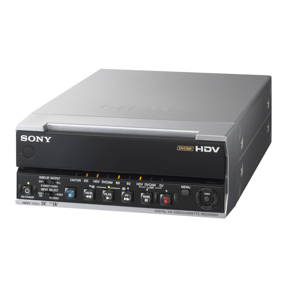
DIGITAL HD VIDEOCASSETTE RECORDER
Sony EMCS Co.
M15P/M15C
RMT-DS5
US Model
Canadian Model
AEP Model
E Model
Chinese Model
Japanese Model
REPAIR PARTS LIST
ADJUSTMENT
INSTRUCTION MANUAL
Published by Kohda TEC
2006L0500-1
© 2006.12
Advertisement
Table of Contents


Need help?
Do you have a question about the HVR-M15J and is the answer not in the manual?
Questions and answers