Table of Contents
Advertisement
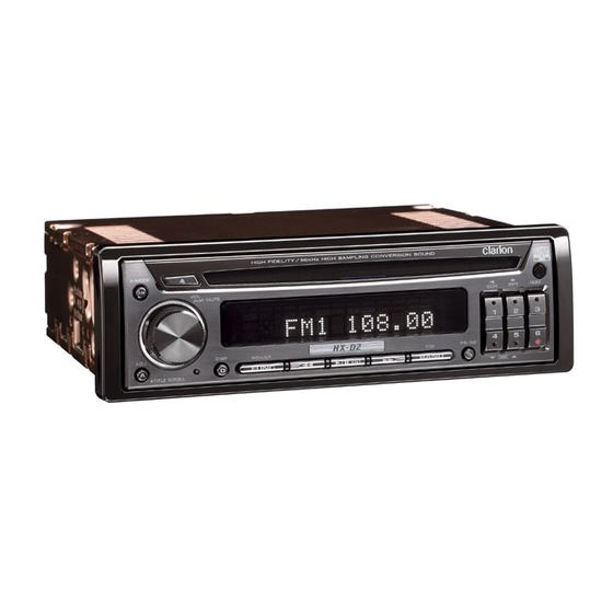
(DRZ9255)
SPECIFICATIONS
FM tuner section
Frequency range:
Usable sensitivity:
50dB quieting sensitivity: 15dBf
Alternate channel selectivity:
Stereo separation:
Frequency response:
AM tuner section
Frequency range:
Usable sensitivity:
CD player section
System:
Usable discs:
Frequency response:
S/N ratio:
Dynamic range:
Distortion:
Audio section
Bass control action:
Treble control action:
Line output level:
DSP/DAC
A/D conversion:
D/A conversion:
Clarion Co., Ltd.
50 Kamitoda, Toda-shi, Saitama 335-8511 Japan
Service Dept.: 5-66 Azuma , Kitamoto-shi, Saitama 364-0007 Japan
Tel: +81-48-541-2335 / 2432 FAX: +81-48-541-2703
87.9MHz to 107.9MHz(U.S.A.)
87.0MHz to 108.0MHz(OTHERS)
9dBf
70dB
35dB (1kHz)
30Hz to 15kHz (+/-3dB)
530kHz to 1710kHz(U.S.A.)
531kHz to 1629kHz(OTHERS)
25uV
Compact disc digital audio system
Compact disc
5Hz to 20kHz (+/-1dB)
112dB (1kHz)
100dB (1kHz)
0.003%(20Hz to 20kHz)
+/-12dB (50Hz)
+/-12dB (10kHz)
Vol.0dB=4V
Vol.+6dB=8V(Max)
(CD 1kHz)
24-bit 64x oversampling
A/D converter
96kHz/24-bit advanced segment
D/A converter
Service Manual
High-Fidelity AM/FM CD Player
Model
(PE-2628B-A / For U.S.A.)
Model
(PE-2628K-A / For other countries)
8x oversampling digital filter
Blocked band attenuation:
Transmitted band attenuation:
Sampling rate converter
Input sampling rate:
Output sampling rate:
DSP:
General
Power supply voltage:
Current consumption:
Dimensions(mm)
Source unit:
DC-DC converter:
Remote control unit:
Weight
Source unit:
DC-DC converter:
Remote control unit:
NOTES
* Use only compact discs bearing the
not play heart-shaped, octagonal, or other specially shaped
compact discs.
Some CDs recorded in CD-R/CD-RW mode may not be
usable.
* We cannot supply PWB with component parts in principle.
When a circuit on PWB has failure, please repair it by
component parts base. Parts which are not mentioned in
service manual are not supplied.
* Specifications and design are subject to change without
notice for further improvement.
- 1 -
Published by Service Dept.
Jun.2004 P
298-6163-00
Printed in Japan
-130 dB
+/-0.00001dB
fs32k, fs44.1k, fs48k,fs96k
fs48k, fs96k
24-bit audio DSP, 34-bit arithmetic
operation (overflow margin 4-bit)
14.4V DC(10.8V to 15.6V allow-
able) negative ground
Less than 5A
178(W)x50(H)x155(D)
163(W)x42(H)x98(D)
52(W)x125(H)x12(D)
1.8kg
700g
50g(including battery)
or
mark.Do
DRZ9255
HX-D2
Advertisement
Table of Contents

Related Manuals for Clarion DRZ9255


Summary of Contents for Clarion DRZ9255
-
Page 1: Specifications
Clarion Co., Ltd. Published by Service Dept. 50 Kamitoda, Toda-shi, Saitama 335-8511 Japan Jun.2004 P 298-6163-00 Service Dept.: 5-66 Azuma , Kitamoto-shi, Saitama 364-0007 Japan Printed in Japan Tel: +81-48-541-2335 / 2432 FAX: +81-48-541-2703 Service Manual High-Fidelity AM/FM CD Player Model (PE-2628B-A / For U.S.A.) - Page 2 CLARION CO.,LTD. 50 KAMITODA,TODA-SHI,SAITAMA-KEN,JAPAN MANUFACTURED: SERIAL No. Clarion Co.,Ltd. Bottom View of DRZ9255 MADE IN To engineers in charge of repair or in- spection of our products. 4. Caution in removal and making wiring connection to the parts for the automobile.
-
Page 3: System Check
Set the correct Parental level. ERROR R Region code error Eject the disc and replace correct region code disc. If an error display other than the ones described above appears, press the reset button. Reset button DRZ9255 - 3 - HX-D2... -
Page 4: Wire Connections
ANALOG Digital Sampling Digital Interface -rate Signal 24bit Receiver Converter Processor Converter IC918 S-RAM 8ch Line-out IC401 IC407 IC418 IC406 IC410 IC421 ANALOG ANALOG ANALOG Low-pass High-quality Converter Filter Electrical Volume Sub-woofer IC250 DC/DC Converter DRZ9255 - 4 - HX-D2... - Page 5 System section KEY ILL S718 DRZ9255 - 5 - HX-D2...
- Page 6 56: CD BUS 3 :I/O: The data bus. pin 57: CD BUS 2 :I/O: The data bus. pin 58: CD BUS 1 :I/O: The data bus. pin 59: CD BUS 0 :I/O: The data bus. DRZ9255 - 6 - HX-D2...
- Page 7 : - : Digital ground. pin 57: OUT ENABLE : O : The output enable command output. pin 58: I/O 0 :I/O: Data input/output. pin 59: I/O 1 :I/O: Data input/output. pin 60: I/O 2 :I/O: Data input/output. DRZ9255 - 7 - HX-D2...
- Page 8 58: TE Z IN : IN : Tracking error signal inpur for zero cross. pin 59: A VDD : - : Positive supply voltage for the Analog sec- tion. pin 60: FOO : O : Focus equalizer output. DRZ9255 - 8 - HX-D2...
- Page 9 : IN : Control data input in serial mode. pin 28: CM 0 : IN : Master clock operation select input in par- allel mode, refer Table 3. : CDTO : O : Control data output in serial mode. DRZ9255 - 9 - HX-D2...
- Page 10 14: L A OUT : O : Left channel audio signal output. pin 15: L A GND : - : Left channel audio signal ground. pin 16: L A IN : IN : Left channel audio signal input. DRZ9255 - 10 - HX-D2...
- Page 11 High Z High Z data out data in 051-7285-08 CD74HC4050PWR Hex Buffer 051-3042-90 OPA2134UA Dual Operational Amplifier 051-3232-90 uPD29M33T 3.3V Voltage Regulator 051-3012-90 OP275GS Dual Operational Amplifier Terminal Description 1: Input(power source) 2: Ground 3: Output DRZ9255 - 11 - HX-D2...
-
Page 12: Exploded View Parts List
EXPLODED VIEW / PARTS LIST Main section (x12) 71 72 62 61 E3 D3 (x5) (x6) (x6) (x3) DRZ9255 - 12 - HX-D2... -
Page 13: Switch Pwb
PART NO. DESCRIPTION Q'TY PART NO. DESCRIPTION Q'TY 378-0546-00 BADGE(PE2628BA:DRZ9255) 347-7379-00 SHADE FILM (PRESET) 378-0547-00 BADGE(PE2628KA:HX-D2) 816-4004-00 FLAT WIRE 371-5778-01 FACE PANEL(PE2628BA) 347-7376-00 E-SHEET 371-5778-00 FACE PANEL(PE2628KA) 373-1036-00 DIAL COVER 309-0798-00 FRONT PLATE 370-6112-01 ESCUTCHEON 714-2004-81 MACHINE SCREW (M2x4) 380-5591-00 KNOB CAP 716-0872-11 SCREW (M1.7x6) -
Page 14: Cd Mechanism Section
966-0638-20 SH-RACK ASSY 621-0623-23 LS-HOLDER 621-0598-27 UPPER GUIDE 621-0624-22 GUIDE RAIL 621-0599-26 ROLLER GUIDE 816-2593-00 LEAD WIRE(PUR) 621-0600-26 SHIFT LEVER 816-2542-01 FLAT WIRE(10P) 621-0601-21 RACK 716-3473-00 IT SCREW(M2 x 3) 621-0602-22 LOCK ARM L 621-0709-20 SH-BASE DRZ9255 - 14 - HX-D2... - Page 15 816-2592-00 LEAD WIRE(BLU) 716-1507-00 SCREW(M2 x 3) 750-3472-21 DR-SPRING F 716-1733-00 SCREW(M1.7 x 2.3) 750-3473-20 DR-SPRING RA 716-3469-00 SCREW( 3 x 4) 750-3474-20 DR-SPRING RB 716-3446-00 SCREW(M1.4 x 2.5) 750-3475-21 DR-SPRING C G16 G15 G7 G10 DRZ9255 - 15 - HX-D2...
-
Page 16: Electrical Parts List
C307 042-0654-52 16V 10uF C420 166-5611-50 560pF CH C612 163-1063-35 16V10uF C308 042-0654-52 16V 10uF C421 166-2211-50 220pF CH C615 168-1032-55 0.01uF K C309 042-0654-52 16V 10uF C422 166-2211-50 220pF CH C900 168-1032-55 0.01uF K DRZ9255 - 16 - HX-D2... - Page 17 051-3297-10 BA4916-V2 L911 010-3406-62 10uH C980 168-1022-55 1000pF K IC301 051-3026-90 NJM4580V L913 010-3103-64 MMZ1608Y1 C981 168-1022-55 1000pF K IC302 051-3026-90 NJM4580V L914 010-3103-64 MMZ1608Y1 C982 168-1032-55 0.01uF K IC303 051-5020-90 M61508FP L915 010-3103-64 MMZ1608Y1 DRZ9255 - 17 - HX-D2...
- Page 18 119-1031-15 1/10W 10k ohm R373 119-1041-15 1/10W 100k ohm Q238 125-0013-97 RN2427 R235 119-2221-15 1/10W 2.2k ohm R401 032-0165-50 1/4W 750 ohm Q239 125-2004-92 RN1402 R255 116-4701-15 1/4W 47 ohm R402 032-0165-50 1/4W 750 ohm DRZ9255 - 18 - HX-D2...
- Page 19 D729 001-0584-23 MA8075 R708 119-6811-15 1/10W 680 ohm D714 001-7078-90 NSCW505T D730 001-0584-23 MA8075 R709 119-6811-15 1/10W 680 ohm 074-1138-60 10P 013-7414-50 CHUCKING COMPONENT) D715 001-7040-91 NSCW100-T D751 001-0516-90 MA111 R710 119-6811-15 1/10W 680 ohm DRZ9255 - 19 - HX-D2...
-
Page 20: Circuit Diagram
(ILL+B) J200 MUTE (VFD-VCC) L230 2 : To Main PWB 2/6 5 : To Main PWB 5/6 : For PE-2628B-A 3 : To Main PWB 3/6 : For PE-2628K-A 4 : To Main PWB 4/6 DRZ9255 - 20 - HX-D2... - Page 21 Main PWB-A(B1) section 2/6 (Tuner block) (FM/AM Tuner) R3 4.7K R4 4.7K C55 22p CH (FM+B) (AM+B) Q4 RN1403 1 : To Main PWB 1/6 2 : To Main PWB 2/6 3 : To Main PWB 3/6 DRZ9255 - 21 - HX-D2...
- Page 22 4-ch RCA pin L-ch AUX IN1 R-ch L-ch AUX IN2 R-ch 1 : To Main PWB 1/6 5 : To Main PWB 5/6 2 : To Main PWB 2/6 4 : To Main PWB 4/6 DRZ9255 - 22 - HX-D2...
- Page 23 (DIR) (SRC) IC916 BS62LV1024STI-70 (SRAM) IC902 SN74AHCT1G08 IC905 SN74AHC1G04 IC901 SN74AHC1G04 (DIGITAL TERMINAL) IC918 UPC29M33T (3.3V STB) 1 : To Main PWB 1/6 3 : To Main PWB 3/6 5 : To Main PWB 5/6 DRZ9255 - 23 - HX-D2...
- Page 24 PCM1792DBR (DAC) To P401(6/6) C983 (OPEN) C975 220p C981 100p 1000p 1 : To Main PWB 1/6 : For PE-2628B-A 3 : To Main PWB 3/6 : For PE-2628K-A 4 : To Main PWB 4/6 DRZ9255 - 24 - HX-D2...
- Page 25 Main PWB-B(B1) section 6/6 MODE 8-ch RCA pin cord (E-VOL, RCA Line out block) L-ch High R-ch HIGH L-ch Mid/Front R-ch MID/FRONT L-ch LOW/REAR Low/Rear R-ch SUB WOOFER NON FADER L-ch Sub-Woofer/Non-Fader R-ch To J402(5/6) To J401(5/6) DRZ9255 - 25 - HX-D2...
- Page 26 SOLDER SIDE: Parts on the solder side seen from the solder side are indicated. Main PWB-B (B1) Main PWB-B (B1) SOLDER SIDE : For PE-2628B-A Main PWB-A (B1) Main PWB-A (B1) : For PE-2628K-A SOLDER SIDE DRZ9255 - 26 - HX-D2...
- Page 27 VFD REMO VFD +B VFD GND R-CH(+) To J101 of CD PWB (page 32) Main PWB-B (B1) Main PWB-B (B1) COMPONENT SIDE Main PWB-A (B1) Main PWB-A (B1) To J702 of Switch PWB(page 29) COMPONENT SIDE DRZ9255 - 27 - HX-D2...
- Page 28 CIRCUIT DIAGRAM Switch PWB(B2) section FL701 (VFD) IC701 M66010GP-201D To P1 of Main PWB (page 20) J702 4.1(FUNC:0.7,EJ:0) IR701 (IR) DRZ9255 - 28 - HX-D2...
-
Page 29: Printed Wiring Board
PRINTED WIRING BOARD Switch PWB(B2) section To P1 of Main PWB (page 27) Switch PWB(B2) Switch PWB(B2) Switch PWB(B2) Switch PWB(B2) COMPONENT SIDE SOLDER SIDE DRZ9255 - 29 - HX-D2... - Page 30 CIRCUIT DIAGRAM DC/DC PWB(B3) section J250 (10PSOCKET) IC202 KR5000199 (VFD DC-DC Converter) IC250 HMA157024 (Audio DC-DC Converter) DRZ9255 - 30 - HX-D2...
- Page 31 DD +15V DD GND DD -15V VFD +B BUS 14V PHONE MUTE ILLUMI ORG/WHT BLK/WHT DD REMO YEL/BLK DD GND VFD REMO VFD GND DC/DC PWB(B3) DC/DC PWB(B3) DC/DC PWB(B3) DC/DC PWB(B3) COMPONENT SIDE SOLDER SIDE DRZ9255 - 31 - HX-D2...
- Page 32 Sled motor (SMA-183-100) R12 2.2K C54 10p C53 10p LED PWB-A (B5) SLED MOTOR SPNDLE MOTOR CD PWB (B4) To J602 of Main PWB SOLDER SIDE (page 27) To Pick up unit LED PWB-B (B5) DRZ9255 - 32 - HX-D2...
Need help?
Do you have a question about the DRZ9255 and is the answer not in the manual?
Questions and answers