Table of Contents
Advertisement
Available languages
Available languages
F F
S S
1 1
1 1
0 0
L L
1 1
F F
S S
1 1
1 1
0 0
L L
1 1
G
G
O
T
O
O
T
O
BEFORE RETURNING THIS PRODUCT FOR ANY REASON PLEASE CALL
BEFORE YOU CALL, HAVE THE CATALOG No. AND DATE CODE AVAILABLE. IN MOST CASES, A
BLACK & DECKER REPRESENTATIVE CAN RESOLVE THE PROBLEM OVER THE PHONE. IF YOU HAVE A SUGGESTION OR COMMENT, GIVE US A
SAVE THIS MANUAL FOR FUTURE REFERENCE.
VEA EL ESPAÑOL EN LA CONTRAPORTADA.
POUR LE FRANÇAIS, VOIR LA COUVERTURE ARRIÈRE.
INSTRUCTIVO DE OPERACIÓN, CENTROS DE SERVICIO Y
PÓLIZA DE GARANTÍA. ADVERTENCIA: LÉASE ESTE
INSTRUCTIVO ANTES DE USAR EL PRODUCTO.
0 0
" "
C C
O O
M M
P P
O O
0 0
" "
C C
O O
M M
P P
O O
INSTRUCTION MANUAL
T
T
HANK
YOU
FOR
HANK
YOU
FOR
.F
.F
WWW
IREST
ORMT
WWW
IREST
ORMT
T
O
REGISTER
T
O
REGISTER
1-800-544-6986
CALL. YOUR FEEDBACK IS VITAL TO BLACK & DECKER.
U U
N N
D D
L L
A A
S S
E E
U U
N N
D D
L L
A A
S S
E E
F
F
CHOOSING
IREST
CHOOSING
IREST
.
/P
.
/P
OOLS
COM
RODUCT
OOLS
COM
RODUCT
YOUR
NEW
PRODUCT
YOUR
NEW
PRODUCT
R R
M M
I I
T T
E E
R R
S S
R R
M M
I I
T T
E E
R R
S S
!
!
ORM
ORM
R
R
EGISTRA
TION
EGISTRA
TION
.
.
A A
W W
A A
W W
Advertisement
Table of Contents

Related Manuals for Black & Decker Fire Storm FS110L


Summary of Contents for Black & Decker Fire Storm FS110L
-
Page 1: Instruction Manual
” ” ” ” INSTRUCTION MANUAL HANK CHOOSING IREST HANK CHOOSING IREST IREST ORMT OOLS RODUCT EGISTRA TION IREST ORMT OOLS RODUCT EGISTRA TION REGISTER YOUR PRODUCT REGISTER YOUR PRODUCT BEFORE RETURNING THIS PRODUCT FOR ANY REASON PLEASE CALL 1-800-544-6986 BEFORE YOU CALL, HAVE THE CATALOG No. -
Page 2: Safety Guidelines - Definitions
SAFETY GUIDELINES - DEFINITIONS This manual contains information that is important for you to know and understand. This information relates to protecting YOUR SAFETY and PREVENTING EQUIPMENT PROBLEMS. To help you recognize this information, we use the symbols below. Please read the manual and pay attention to these sections. Indicates an imminently hazardous situation which, if not avoided, will result in death or serious injury. - Page 3 FAILURE TO FOLLOW THESE RULES MAY RESULT IN SERIOUS PERSONAL INJURY. FOR YOUR OWN SAFETY, READ AND USE RECOMMENDED ACCESSORIES. The use UNDERSTAND THE INSTRUCTION MANUAL of accessories and attachments not BEFORE OPERATING THE MACHINE. Learning the recommended by Black & Decker may cause machine’s application, limitations, and specific damage to the machine or injury to the user.
-
Page 4: Additional Safety Rules For Miter Saws
ADDITIONAL SAFETY RULES FOR MITER SAWS FAILURE TO FOLLOW THESE RULES MAY RESULT IN SERIOUS INJURY. DO NOT OPERATE THIS MACHINE until it is NEVER CUT SMALL PIECES. Cutting small pieces completely assembled and installed according to the (where your hand would be within 6” of the saw blade) instructions. -
Page 5: Additional Safety Rules For The Laser
ADDITIONAL SAFETY RULES FOR THE LASER For your convenience and safety the FOR LASER SAFETY OBSERVE THE FOLLOWING: following labels are on your tool. • LASER LIGHT - DO NOT STARE INTO BEAM, APERTURE, or into a reflection from a mirror-like surface Fig. A & B. AVOID EXPOSURE - LASER LIGHT IS EMITTED FROM FRONT GUARD •... -
Page 6: Functional Description
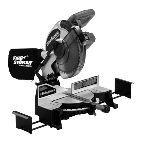
FOREWORD Model FS110L is a 10" Compound Power Laser Miter Saw designed to cut wood, plastic, and aluminum. Compound angle and bevel cutting are easy and accurate. It can crosscut up to 5-5/8" x 2-3/4", miter at 45° both left and right 4"... -
Page 7: Carton Contents
CARTON CONTENTS 1. Miter Saw 2. Dust Bag 3. Clamp 4. 5mm Hex Wrench 5. 1/8” Hex Wrench 6. 1/2” Blade Wrench Fig. 1 Fig. 2 Remove the miter saw and all loose items from the carton. Lifting the miter saw by the switch handle can cause misalignment. Always lift the machine by the base or the carrying handle. -
Page 8: Fastening Machine To Supporting Surface
ATTACHING DUST BAG Attach the dust bag (A) Fig. 5 to the dust spout (B) making sure the wire ring (C) is engaged with the ridge in the spout (see inset). Fig. 5 FASTENING MACHINE TO SUPPORTING SURFACE Before operating your compound miter saw, mount it to a sturdy workbench or other supporting surface. -
Page 9: Locking The Switch In The "Off" Position
STARTING AND STOPPING THE MITER SAW To start the miter saw, depress the switch trigger (A) Fig. 9. To stop the miter saw, release the switch trigger. This saw is equipped with an automatic electric blade brake. As soon as the switch trigger (A) Fig. 9 is released, the electric brake is activated and stops the blade in seconds. -
Page 10: Pointer And Scale
ADJUSTING THE SLIDING FIT BETWEEN THE MOVABLE TABLE AND THE BASE DISCONNECT THE MACHINE FROM THE POWER SOURCE . To adjust the sliding fit between the movable table and the base, turn the nut (A) Fig. 12A clockwise to increase the sliding fit (opposite to decrease the fit). -
Page 11: Adjusting Sliding Fence
ADJUSTING SLIDING FENCE The sliding fence (A) Fig. 15A provides support for extra large workpieces used with your saw. Set it as close as possible to the saw blade. When miter cutting (blade 90° to the table and at an angle to the right or left), set the fence all the way toward the blade (Fig. -
Page 12: Adjusting Blade Parallel To Table Slot
ADJUSTING BLADE PARALLEL TO TABLE SLOT DISCONNECT MACHINE FROM POWER SOURCE. 1. Lower the cutting arm. The saw blade (A) Fig. 20 should be parallel to the left edge (B) of the table opening. 2. If an adjustment is necessary, loosen two screws (C) Inset, and move the cutting arm until the blade is parallel with the left edge (B) of the table opening and centered in the slot. -
Page 13: Adjusting Tension Of Cuttinghead Return Spring
Fig. 24 Fig. 25 Fig. 26 Fig. 27 ADJUSTING TENSION OF CUTTINGHEAD RETURN SPRING CUTTING HEAD MUST RETURN QUICKLY TO THE UP POSITION. DISCONNECT MACHINE FROM POWER SOURCE. The tension of the cuttinghead return spring was adjusted at the factory so that the cuttinghead returns to the “up” position after a cut has been made. - Page 14 ADJUSTING THE LOWER BLADE GUARD DISCONNECT THE MACHINE FROM POWER SOURCE. This machine incorporates a blade guard (A) Fig. 27B to cover the rear section of the blade. After an extended period of use, the movable lower blade guard may not operate smoothly when the cuttinghead is lowered.
-
Page 15: Laser Maintenance
Fig. B Fig. C SCREW Fig. D Fig. A TO CHECK FOR VERTICAL ALIGNMENT 1. The vertical alignment is set correctly when the line does not move horizontally (sideways) as the cutting head is raised and lowered. If the vertical alignment is correct, disregard this section and move to “TO SET KERF ADJUSTMENT”. -
Page 16: Typical Operations And Helpful Hints
TYPICAL OPERATIONS AND HELPFUL HINTS If the workpiece causes your hand to be in the hazard zone within 6” of the saw blade, clamp the workpiece in place before making the cut. Cuttinghead must return quickly to the full up position. Sluggish or incomplete return of the cuttinghead will effect lower guard operation possibly resulting in personal injury. -
Page 17: Cutting Aluminum
Fig. 30C Fig. 30D Fig. 30F Fig. 30E CUTTING ALUMINUM Aluminum extrusions used for making aluminum screens and storm windows can easily be cut with your compound miter saw when fitted with a blade recommended for this material. The blade supplied with this saw is not recommended for cutting aluminum. -
Page 18: Cutting Crown Molding
CUTTING CROWN MOLDING One of the many features of the saw is the ease of cutting crown molding. The following is an example of cutting both inside and outside corners on 52°/38° wall angle crown molding. 1. Move the table to the 31.62° right miter position and lock the table in position. -
Page 19: Changing The Blade
MAINTENANCE CHANGING THE BLADE Use only cross-cutting saw blades. When using carbide-tipped blades, do not use blades with deep gullets as they can deflect and contact the guard. Use only 10" diameter saw blades rated for 5200 rpm or higher, and have 5/8" diameter arbor holes. Disconnect machine from power source. -
Page 20: Brush Inspection And Replacement
BRUSH INSPECTION AND REPLACEMENT Brush life varies. It depends on the load on the motor. Check the brushes after the first 50 hours of use for a new machine or after a new set of brushes has been installed. After the first check, examine them after about 10 hours of use until such time that replacement is necessary. -
Page 21: Troubleshooting Guide
Trouble Shooting Guide BE SURE TO FOLLOW SAFETY RULES AND INSTRUCTIONS TROUBLE! SAW WILL NOT START WHAT’S WRONG? WHAT TO DO… 1.Saw not plugged in. 1.Plug in saw. 2.Fuse blown or circuit breaker tripped. 2.Replace fuse or reset circuit breaker. 3.Cord damaged. - Page 22 À À À À MODE D’EMPLOI ’ ’ ’ ’ É É É É...
-
Page 23: Règles Générales De Sécurité
LIGNES DIRECTRICES EN MATIÈRE DE SÉCURITÉ — DÉFINITIONS Ce mode d’emploi contient de l’information qu’il est important de connaître et de comprendre. Cette information concerne VOTRE SÉCURITÉ et vise à ÉVITER TOUT PROBLÈME D’ÉQUIPEMENT. Pour aider à reconnaître ces informations, nous utilisons les symboles ci-dessous. Veuillez lire le mode d’emploi et porter une attention accrue à ces sections. - Page 24 NÉGLIGER DE SUIVRE CES RÈGLES RISQUE D’ENTRAÎNER DES BLESSURES AVERTISSEMENT CORPORELLES GRAVES. lequel il n’a pas été conçu. Dans le cas contraire, POUR SA PROPRE SÉCURITÉ, LIRE ET l'outil peut être endommagé et/ou vous pouvez être COMPRENDRE LE MODE D’EMPLOI AVANT blessé.
- Page 25 RÈGLES DE SÉCURITÉ SUPPLÉMENTAIRES POUR LES SCIES À ONGLET NÉGLIGER DE SUIVRE CES RÈGLES RISQUE D’ENTRAÎNER DES BLESSURES GRAVES. AVERTISSEMENT de la lame à grande vitesse, provoquant des blessures NE PAS FAIRE FONCTIONNER CETTE MACHINE avant graves. qu’elle ne soit entièrement assemblée et installée NE JAMAIS COUPER DE PETITES PIÈCES.
-
Page 26: Connexions Électriques
RÈGLES DE SÉCURITÉ SUPPLÉMENTAIRES POUR LE LASER SUIVRE LES CONSIGNES SUIVANTES POUR UNE Pour plus de commodité et de ATTENTION UTILISATION SÉCURITAIRE DU LASER : sécurité, les étiquettes suivantes sont • RAYONNEMENT LASER - NE PAS FIXER DU REGARD LE FAISCEAU, apposées sur votre outil. -
Page 27: Description Fonctionnelle
16 AWG AVANT-PROPOS 10-12 15,2 à 30,5 14 AWG Le modèle FS110L est une scie électrique à onglets mixtes de 10 po 10-12 30,5 à 45,7 12 AWG (254 mm) à système laser destinée à couper le bois, le plastique et l’aluminium. -
Page 28: Contenu Du Carton
CONTENU DU CARTON 1. Scie à onglets 2. Sac à poussière 3. Bride de fixation 4. Clé hexagonale de 5mm 5. Clé hexagonale de 1/2 po (3,2 mm) 6. Clé de lame de 1/2 po (12,7 mm) Retirer du carton la scie à onglets ainsi que toutes les pièces. Soulever la scie à... - Page 29 DÉMARRAGE ET ARRÊT DE LA SCIE À ONGLETS Pour démarrer la scie à onglets, enfoncer la détente (A, fig. 9). Pour arrêter la scie à onglets, relâcher la détente. Cette scie est dotée d’un frein de lame électrique automatique. Dès que la détente (A, fig. 9) est relâchée, le frein électrique est activé...
- Page 30 RÉGLAGE DU GUIDE COULISSANT Le guide coulissant (A) fig. 15A offre un soutien pour les pièces extra larges qui seront coupées avec la scie. L’installer aussi près que possible de la lame de scie. Lors d’une coupe à onglet (soit la lame à 90° par rapport à la table et incliné...
- Page 31 RÉGLAGE DE LA TENSION DU RESSORT DE RAPPEL DE LA FRAISE ROTATIVE LA TÊTE DE COUPE DOIT RETOURNER RAPIDEMENT À LA POSITION ÉLEVÉE. AVERTISSEMENT DÉBRANCHER LA MACHINE DE LA SOURCE D’ALIMENTATION. La tension du ressort de rappel de la fraise rotative a été réglée à l’usine de sorte que la fraise rotative se remette en position «...
- Page 32 VÉRIFICATION DE L’ALIGNEMENT VERTICAL 1. L’alignement vertical est bien réglé si la raie ne bouge pas sur le plan horizontal (latéralement) lors de la montée et de la descente de la tête de coupe. Si l’alignement vertical est correct, ne pas tenir compte de cette section et passer à...
- Page 33 OPÉRATIONS DE COUPE GÉNÉRALES Votre machine a la capacité d'effectuer des coupes sur des morceaux de bois standards 2 x 4, à plat ou sur les bords, à angle d’onglet gauche et droit à 45° (fig. 30A). Un morceau de bois standard 2 x 6 (5,1 x 15,2 cm) peut être coupé à angle droit de 90° en un passage (fig. 30B) ou à...
-
Page 34: Entretien
ENTRETIEN CHANGEMENT DE LA LAME Utiliser uniquement des lames de scie à tronçonner. AVERTISSEMENT Avec l'utilisation de lames à pointe carburée, ne pas utiliser de lames à dents très espacées AVERTISSEMENT car elles peuvent entrer en contact avec le pare-main et le faire dévier. AVERTISSEMENT Utiliser uniquement des lames de scie de 10 po (254 mm) de diamètre conçues pour un régime d’au moins 5200 tr/min et ayant des trous d’axe de 5/8 po (158,7 mm). -
Page 35: Guide De Dépannage
Guide de dépannage SUIVRE LES RÈGLES ET CONSIGNES DE SÉCURITÉ PROBLÈME ! LA SCIE NE DÉMARRE PAS QUEL EST LE PROBLÈME ? QUE FAIRE… 1.Scie non branchée. 1.Brancher la scie. 2.Fusible grillé ou disjoncteur déclenché.2.Remplacer le fusible ou réinitialiser le disjoncteur. 3.Cordon endommagé. - Page 36 " " " " MANUAL DE INSTRUCCIONES ¡ ¡ ¡ ¡...
-
Page 37: Normas Generales De Seguridad
DEFINICIONES DE LAS NORMAS DE SEGURIDAD Es importante que usted conozca y comprenda la información incluida en este manual. Esta información se relaciona con la protección de SU SEGURIDAD y la PREVENCIÓN DE PROBLEMAS CON EL EQUIPO. Para ayudarlo a reconocer esta información, utilizamos los siguientes símbolos. - Page 38 LA FALTA DE CUMPLIMIENTO DE ESTAS NORMAS PUEDE PROVOCAR LESIONES PERSONALES GRAVES. POR SU PROPIA SEGURIDAD, LEA y comprenda UTILICE LA MÁQUINA ADECUADA. No fuerce una EL MANUAL DE INSTRUCCIONES ANTES DE máquina o un dispositivo en tareas para las que no OPERAR LA MÁQUINA.
- Page 39 NORMAS DE SEGURIDAD ADICIONALES PARA LAS SIERRAS INGLETADORAS LA FALTA DE CUMPLIMIENTO DE ESTAS NORMAS PUEDE PROVOCAR LESIONES GRAVES. NO OPERE ESTA MÁQUINA HASTA que no esté armada NUNCA CORTE PIEZAS PEQUEÑAS. El corte de piezas e instalada completamente, según las instrucciones. Una pequeñas (en los que su mano puede estar a menos de máquina montada de manera incorrecta puede provocar 152,4 mm (6”) de la hoja de la sierra) puede llevarle la...
-
Page 40: Conexiones Eléctricas
OTRAS REGLAS DE SEGURIDAD PARA EL LÁSER PARA SEGURIDAD DEL LÁSER, CUMPLA CON LO SIGUIENTE: Para su comodidad y seguridad, el • LÁSER: NO FIJE LA VISTA EN EL RAYO, en el orificio o en un reflejo sobre láser incluye las siguientes etiquetas: superficies similares a un espejo. -
Page 41: Descripción De Las Funciones
DESCRIPCIÓN DE LAS FUNCIONES INTRODUCCIÓN El modelo FS110L es una Sierra ingletadora eléctrica compuesta con láser de 254 mm (10”) diseñada para cortar madera, plástico y aluminio. Los cortes biselados y en ángulo compuestos son fáciles de realizar y precisos. Puede realizar cortes transversales de hasta 142,875 mm x 69,85 mm (5 5/8"... -
Page 42: Desembalaje Y Limpieza
DESEMBALAJE Y LIMPIEZA Desembale cuidadosamente la máquina y todos los elementos sueltos del o los contenedores de envío. Quite el recubrimiento protector de todas las superficies sin pintura. Puede quitarlo con un trapo suave humedecido con queroseno (no utilice acetona, gasolina ni solvente de barniz para este fin). Luego de limpiar, cubra las superficies sin pintura con cera en pasta de buena calidad que se utiliza para los pisos del hogar. - Page 43 CONTROLES DE OPERACIÓN Y AJUSTES ÁREA DE PELIGRO EN LA MESA El área comprendida entre las dos líneas rojas (A), Figura 7, en la mesa es considerada una “zona de peligro”. Nunca coloque las manos dentro de esta área mientras la máquina esté funcionando.
- Page 44 INDICADOR Y ESCALA Se incluye un indicador (A), Figura 13, para marcar el ángulo de corte real. Cada línea en la escala (B) representa 1 grado. Cuando el indicador se mueve desde una línea a la otra en la escala, el ángulo de corte se modifica en 1 grado. BLOQUEO DEL CABEZAL DE CORTE EN LA POSICIÓN HACIA ABAJO Al trasladar la sierra, bloquee el cabezal de corte en la posición hacia abajo.
- Page 45 AJUSTE DEL RECORRIDO DESCENDENTE DE LA HOJA DE LA SIERRA DESCONECTE LA MÁQUINA DEL SUMINISTRO DE ENERGÍA. 1. El recorrido descendente de la hoja de la sierra debe ser limitado para evitar que entre en contacto con cualquier superficie de metal de la máquina. Puede realizar este ajuste si afloja la tuerca de seguridad (A), Figura 21, y gira el tornillo de ajuste (B) para un lado o el otro.
- Page 46 UTILIZACIÓN Y REGULACIÓN DEL LÁSER FUNCIONAMIENTO DEL LÁSER La unidad láser operada con baterías (las baterías AA no están incluidas) está montada en una cubierta que se encuentra en el protector superior de la hoja de la sierra ingletadora (Fig. A). (Para insertar las baterías, retire el tornillo (C), Figura B, y deslice la cubierta de las baterías (D) desde el mango).
- Page 47 MANTENIMIENTO DEL LÁSER Para obtener el mejor rendimiento del láser, realice el siguiente mantenimiento en forma regular: 1. Limpie cuidadosamente el aserrín de cada lente del láser (A) Fig. I con un hisopo de algodón (B). No utilice solventes de ningún tipo porque podrían dañar los lentes. Evite tocar los puntos filosos de la hoja con las manos o los dedos.
-
Page 48: Corte De Molduras De Corona
CORTE DE MATERIAL CURVADO Al cortar piezas planas, verifique que el material no esté curvado. Si es así, asegúrese de que el material esté ubicado en la mesa como lo muestra la Figura 33. Cuando el material esté en una posición incorrecta (Figura 34), morderá la hoja cerca del final del corte y es posible que la sierra salte o se mueva. -
Page 49: Guía De Solución De Problemas
RETIRE LAS LLAVES (A), FIGURA 39, Y (A) FIGURA 40, ANTES DE ENCENDER LA MÁQUINA. Se debe volver a colocar el soporte de la protección en su posición original y se debe ajustar el tornillo antes de poner en funcionamiento a la sierra. El incumplimiento de esta instrucción podría permitir que la protección se ponga en contacto con la hoja de la sierra en rotación provocando daños a la sierra y daños personales graves INSPECCIÓN Y REEMPLAZO DE LOS CEPILLOS... - Page 50 “HERRAMIENTAS ELECTRICAS” BOSQUES DE LAS LOMAS, 05120 MEXICO, en la sección amarilla. D.F. TEL (55)5326-7100 ESPECIFICACIONES 120 Volts, 60 Hz, 15 Amps, 1674 Watts Cat.No. FS110L Form No. 90520290 APRIL ‘07 Copyright 2007 Black & Decker Printed in China ©...
Need help?
Do you have a question about the Fire Storm FS110L and is the answer not in the manual?
Questions and answers
adjust fence
To adjust the fence on a Black & Decker FS110L:
1. Check if the blade is square to the fence. If not, adjust the fence accordingly.
2. If making a bevel cut, move the sliding fence to provide clearance for the blade and guard. The amount of movement depends on the bevel angle.
3. Refer to the section “Adjusting Sliding Fence” for specific instructions related to bevel cuts.
Always make sure the fence is properly aligned before cutting.
This answer is automatically generated
Part list
The part list for the Black & Decker FS110L includes:
1. Miter saw
2. Dust bag
3. Clamp
4. 5 mm hex key
5. 1/8 in (3.2 mm) hex key
6. 1/2 in (12.7 mm) blade wrench
This answer is automatically generated