
Related Manuals for Bush Hog 2347 QT


Summary of Contents for Bush Hog 2347 QT
- Page 1 BUSH HOG ® Model 2347 QT Front End Loader Operator’s Manual OPERATION l l MAINTENANCE 1207 $4.00 50057986...
- Page 2 If your manual should become lost or destroyed, Bush Hog will be glad to provide you with a new copy. Order from Bush Hog, P. O. Box 1039, Selma, Alabama 36702-1039. Most of our manuals can also be downloaded from our website at www.bushhog.com.
-
Page 3: Table Of Contents
It is the Retail Customer’s responsibility to deliver the product to the authorized Bush Hog Dealer, from whom he purchased it, for service or replacement of defective parts which are covered by warranty. -
Page 4: Warranty
2. If the unit has been subjected to misapplication, abuse, misuse, negligence, fire or other accident. 3. If parts not made or supplied by Bush Hog have been used in connection with the unit, if, in the sole judge- ment of Bush Hog such use affects its performance, stability or reliability. -
Page 5: Dealer Preparation Check List
DEALER PREPARATION CHECK LIST 2347 QT LOADER BEFORE DELIVERING MACHINE - The following check list should be completed. Use the Operator’s Manual as a guide. o Machine properly assembled. o All safety decals readable. (See decal page) o All bolts tightened to torque specifications given in torque chart. -
Page 6: Safety Precautions
IMPORTANT SAFETY PRECAUTIONS This symbol is used to call attention to safe- ty precautions that should be followed by the operator to avoid accidents. When you see this symbol, carefully read the message that follows and heed its advice. Failure to comply with safety precautions could result in serious bodily injury. - Page 7 SAFETY PRECAUTIONS CONTINUED 9. Use a piece of cardboard or wood rather than hands and wear eye protection when searching for hydraulic leaks. Escaping hydraulic oil under pressure can penetrate skin. If oil is injected into skin, it must be surgically removed within a few hours by a doctor or gangrene may result.
-
Page 8: Federal Laws & Regulations
IMPORTANT FEDERAL LAWS AND REGULATIONS* CONCERNING EMPLOYERS, EMPLOYEES AND OPERATIONS. *(This section is intended to explain in broad terms the concept and effect of the following federal laws and regulations. It is not intended as a legal interpretation of the laws and should not be considered as such). U.S. -
Page 9: Introduction & Description
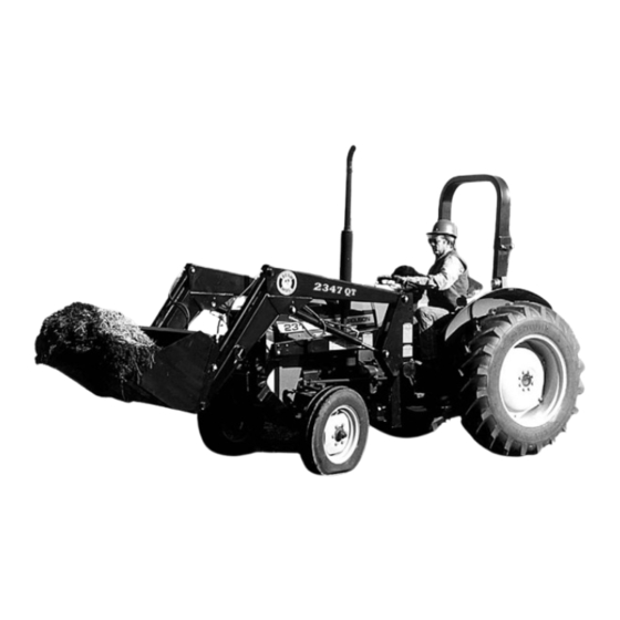
Bucket 1-1 INTRODUCTION 1-2 DESCRIPTION We are pleased to have you as a Bush Hog cus- The model 2347 QT Front End Loader (Figure 1-1) tomer. Your Front End Loader has been carefully is designed for two wheel and four wheel drive trac- designed to give maximum service with minimum tors. - Page 10 Table 1-1 TECHNICAL SPECIFICATIONS SERIES LOADER 2347QT M a x im u m L ift H e ig h t - M e a s u re d a t P iv o t P in 1 0 7 in . M a x im u m L ift H e ig h t - U n d e r L e v e l B u c k e t 1 0 1 in .
-
Page 11: Loader Mounting & Dismounting
SECTION II LOADER MOUNTING AND DISMOUNTING 2-1 PREPARING TRACTOR CAUTION TRACTORS THAT HAVE MOVABLE Figure 2-1 AXLES MUST BE SET FORWARD IN THE LONG WHEELBASE POSITION AS SHOWN IN FIGURE 2-1 TO PREVENT EXCESSIVE LEVERAGE BEING EXERT- ED ON THE TRACTOR FRAME. FAILURE TO DO SO CAN RESULT IN PERSONAL INJURY AND EQUIPMENT DAMAGE. - Page 12 Figure 2-4 Cuff Arrangement WARNING USE CAUTION WHEN MOUNTING LOADERS EQUIPPED WITH OPTIONAL CONTROL VALVE ON TRACTORS EQUIPPED WITH CANOPY. RAISING Pivot Pin LOADER SUBFRAME TOO HIGH CAN PINCH HAND BETWEEN CONTROL HANDLE AND CANOPY CAUSING INJURY. D. With tractor at idle speed, carefully activate boom cylinders to raise/lower cross tube until it Cuff aligns with front bracket channel.
-
Page 13: Dismounting Loader
Figure 2-6 Cylinder Mounting Bushing ing bushing in relation to the subframe. (Figure 2-6) 2-3 DISMOUNTING LOADER Remember this position to aid in aligning cross tube with front bracket when loader is being mounted to Dismount loader on firm, level ground to facilitate tractor. -
Page 14: Operating Instructions
Figure 2-8 Loader Dismounted subframe raises up off rear bracket. C. Lower boom until parking stands contact H. With tractor at idle speed, carefully activate ground. boom cylinder until cross tube is free of pressure D. Extend bucket cylinders until cutting edge of within front bracket channel. - Page 15 ...a level bucket throughout the lifting cycle resists FILLING THE BUCKET bucket lift and increases breakaway effort. Approach and enter the pile with a level bucket. NOTE; Do not be concerned if the bucket is not com- pletely filled during each pass. Maximum productivity is determined by the amount of material loaded in a given period of time.
- Page 16 DUMPING THE BUCKET CARRYING THE LOAD Position the bucket as low as possible below the Lift the bucket high enough to clear the side of the level of the tractor hood for maximum stability and vehicle. Move the tractor in as close to the side of visibility, whether the bucket is loaded or empty.
- Page 17 OPERATING WITH FLOAT CONTROL During hard surface operation, keep the bucket level and put the lift control in the float position to permit the bucket to float on the working surface. If hydraulic down pressure is exerted on the bucket, it will wear faster than normal.
- Page 18 PEELING AND SCRAPING BACKFILLING 6” Backgrade occasionally with a loaded bucket to keep the working surface free of ruts and holes. Use a slight bucket angle, travel forward, and hold the Hold the lift control forward in float position so the lift control forward to start the cut.
-
Page 19: Bale Spear Operation
Do not use front end loaders for handling large heavy objects such as logs or oil drums. Handle large round hay bales only when loader is equipped with Bush Hog Bale Spear Attachment. Handling large heavy objects can be Leave dirt in the bucket because dumping on each extremely dangerous due to: pass wastes time. -
Page 20: Fork Lift Operation
3-4 FORK LIFT OPERATION 3-5 QUICK HITCH OPERATION WARNING The quick hitch (Figure 3-4) is designed to allow easy mounting and dismounting of attachments from TO AVOID SERIOUS INJURY OR DEATH: loader. With attachment on flat, level surface, mount H H NEVER LIFT LARGE ROUND HAY as follows: BALES OR OTHER LOADS ON THE FORK LIFT ATTACHMENT THAT... -
Page 21: Maintenance
Do not exceed 3000 psi as this will dam- age components possibly causing serious injury. The Bush Hog control valve is pre-set at the factory and should not be adjusted. Check Tractor... -
Page 22: Troubleshooting
Hydraulic control valve relief stuck See your tractor manual for proper adjust- center tractor hydraulic system. open. ment or Bush Hog dealer for loader valve. Hydraulic control valve relief set (3000 PSI is maximum pressure relief too low. setting recommended) Loader lift and bucket tilt controls do not work Hoses improperly connected. -
Page 23: Assembly
HAVE ANY QUESTIONS REGARDING THE PROP- devices. ER ASSEMBLY OR OPERATION, CONTACT YOUR AUTHORIZED BUSH HOG DEALER OR 2 Select an area for assembly that is clean and REPRESENTATIVE. free of any debris which might cause persons working on the assembly to trip. - Page 24 Figure 5-2 Parking Stands Installed Figure 5-4 Cuff Arrangement Removable Pin Subframe F. Connect hydraulic hoses to loader as shown in Figure 5-3. If optional hydraulic valve is used, refer to paragraphs 5-2 and 5-3 for valve and stand assembly instructions. Cuff G.
-
Page 25: Hydraulic Valve Stand Assembly
Figure 5-5 Valve Stand Assembly Optional Mounting Bracket Dual Handle Valve Single Handle Valve Operational Shield Decal 1/2 x 1-1/2” 3/8 x 1-1/4” 5/8 x 6-1/2” 5/16 X 2-1/2” 5/16 X 3” 5/16 x 3” Mounting Bracket 1/2 X 3” Valve 1/2 X 1-1/2”... -
Page 26: Hydraulic Valve Plumbing
5-3 OPTIONAL HYDRAULIC VALVE D. Remove open center plug. E. Install the closed center plug furnished with PLUMBING INSTRUCTIONS valve. Note: When converting to closed center con- A. Mount valve assembly to valve plate using fas- figuration open center plug is removed from valve ten ers provided. -
Page 27: Power Beyond Plumbing
5-4 BASIC POWER BEYOND PLUMBING INSTRUCTIONS IMPORTANT When loader hydraulics are disconnected from tractor hydraulics, hoses A & B must be connected to complete tractor hydraulic circuit. FAILURE TO DO THIS WILL CAUSE SERIOUS DAMAGE TRACTOR HYDRAULIC SYSTEM. Open Center Plug Figure 5-7 Power Beyond... -
Page 28: Fork Lift Option
5-5 FORK LIFT OPTION Raise the positioning lock pins at the top of each fork. Place fork in the middle of the frame over the notch in the lower edge. Slide forks to desired posi- tions and lower pins to lock forks in place. Guard Mainframe Lock Pin... -
Page 29: Safety Decals
To promote safe operation, Bush Hog supplies safety decals on all products manufactured. Because damages can occur to safety decals either through shipment, use or reconditioning, Bush Hog will, upon request, provide safety decals for any of our products in the field at no charge. Contact your authorized Bush Hog dealer for more information. -
Page 30: Torque Specifications
TORQUE SPECIFICATIONS Proper toque for American fasteners used on Bush Hog equipment. Recommended Torque in Foot Pounds (Newton Meters).* AMERICAN B O L T D IA M E T E R Bolt Head Markings W R E N C H (IN .) “B ”... - Page 31 P.O. Box 1039 Selma, AL 36702-1039 Telephone (334) 874-2700 www.bushhog.com...
Need help?
Do you have a question about the 2347 QT and is the answer not in the manual?
Questions and answers