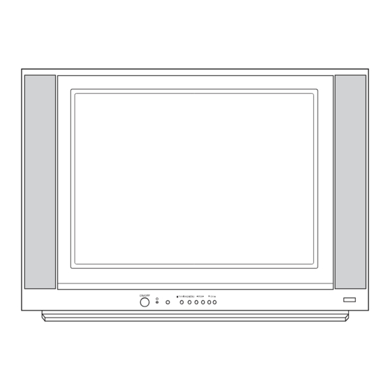
Summary of Contents for LG RP-21FD10
-
Page 1: Service Manual
COLOR TV SERVICE MANUAL CHASSIS : SC-023A MODEL : RP-21FD10 RN-21FD10T CAUTION BEFORE SERVICING THE CHASSIS, READ THE SAFETY PRECAUTIONS IN THIS MANUAL. -
Page 2: Table Of Contents
CONTENTS SAFETY PRECAUTIONS ...................................3 ADJUSTMENT INSTRUCTIONS ................................4 EXPLODED VIEW .......................................8 EXPLODED VIEW PARTS LIST .................................9 REPLACEMENT PARTS LIST ..................................10 SCHEMATIC DIAGRAM ....................................COMPONENT LOCATION GUIDE .........................Back of Circuit Diagram PRINTED CIRCUIT BOARD............................Back of Circuit Diagram BLOCK DIAGRAM ..............................Back of Circuit Diagram SPECIFICATIONS POWER INPUT ............................... -
Page 3: Safety Precautions
SAFETY PRECAUTIONS 1. Before returning an instrument to the customer, always make a safety they are serviced. (X-radiation protection circuits also may be called check of the entire instrument, including, but not limited to, the "horizontal disable" or "hold-down.") Read and apply the high voltage following items: limits and, if the chassis is so equipped, the X-radiation protection circuit a. -
Page 4: Adjustment Instruction
ADJUSTMENT INSTRUCTION 1. Application Object 5. Purity and Convergence Adjustment These instructions are applied to SC-023A chassis. 5.1 Purity Adjustment (1) Preliminary steps 1. Receive Red Raster Pattern. 2. Notes 2. Degauss CPT and Cabinet with degaussing coil. (1) Because this is not a hot chassis, it is not necessary to use an isolation transformer. -
Page 5: White Balance Adjustment
6. Rotate the 6-Pole magnets keeping the angle between 5. Repeat 1 ~ 4 until the color coordinates in High and two 6-Pole magnets until horizontal Red and Blue lines Low color satisfies the Table. are unified. 6. Check the adjusted color coordinates with the white balance meter. - Page 6 10. Deflection Data Adjustment 10.1 Preliminary Steps (2) Vertical Position Adjustment (1) Set the Deflection data with the SVC Remote control. Select SUB 2(V-POS) and adjust until the mechanical (2) Enter into Deflection adjustment mode by “INSTART” center point and the center of screen unite. button.
- Page 7 11.2 14/20/21¡ ¡ – – Normal Model Menu Adjustment Range Initial setting Remark S - 0 RF AGC AAGC Voltage Adj. 0 ~ 63 Necessary S - 1 H POSIT Horizontal Postilion 0 ~ 31 Necessary S - 2 V-POS Vertical Position 0 ~ 7 Necessary...
-
Page 8: Exploded View
EXPLODED VIEW - 8 -... -
Page 9: Exploded View Parts List
CABINET ASSEMBLY *LGETT 5020V00893A BUTTON,CONTROL RT-21FD10 ABS, HF-380 6KEY . 320-062E SPRING,KNOB 5020V00873A BUTTON,POWER RT-29FB70 ABS 1KEY . 3809V00471C BACK COVER ASSEMBLY,RP-21FD10 DVD(1PHONE) IN -> CM 3809V00471B BACK COVER ASSEMBLY *LGETT CHASSIS ASSEMBLY,MAIN SC023A 21F/ST/F(EAR)/DVD(11P)/PUSH/FD10/LGEIN 3141VMNN22K 3141VMNS61B CHASSIS ASSEMBLY,MAIN SC023A *LGETT 351-009A... -
Page 10: Replacement Parts List
REPLACEMENT PARTS LIST For Capacitor & Resistors, the CC, CX, CK, CN : Ceramic RD : Carbon Film charactors at 2nd and 3rd digit CQ : Polyestor RS : Metal Oxide Film in the P/No. means as follows; CE : Electrolytic RN : Metal Film RUN DATE : 2004.5.12 RF : Fusible... - Page 11 For Capacitor & Resistors, the CC, CX, CK, CN : Ceramic RD : Carbon Film charactors at 2nd and 3rd digit CQ : Polyestor RS : Metal Oxide Film in the P/No. means as follows; CE : Electrolytic RN : Metal Film RF : Fusible LOCA.
- Page 12 For Capacitor & Resistors, the CC, CX, CK, CN : Ceramic RD : Carbon Film charactors at 2nd and 3rd digit CQ : Polyestor RS : Metal Oxide Film in the P/No. means as follows; CE : Electrolytic RN : Metal Film RF : Fusible LOCA.
- Page 13 For Capacitor & Resistors, the CC, CX, CK, CN : Ceramic RD : Carbon Film charactors at 2nd and 3rd digit CQ : Polyestor RS : Metal Oxide Film in the P/No. means as follows; CE : Electrolytic RN : Metal Film RF : Fusible LOCA.
- Page 14 For Capacitor & Resistors, the CC, CX, CK, CN : Ceramic RD : Carbon Film charactors at 2nd and 3rd digit CQ : Polyestor RS : Metal Oxide Film in the P/No. means as follows; CE : Electrolytic RN : Metal Film RF : Fusible LOCA.
- Page 15 CONNECTOR ASSEMBLY,6P 2.5MM PA01 6726VV0006H REMOTE CONTROLLER RECEIVER,38KHZ SK901 6620VBC003A SOCKET,CPT PCS030A 8PIN 14/360 TH802 163-051F THERMISTOR,PTC J503P84D140M290Q +/ 20% TU101 6700NFNS11A TUNER,TAEUH001F LG NTSC VD801 164-003G VARISTOR,TVR621D14A 620V 10% ACCESSORIES 3828VA0393R MANUAL,OWNERS LGECM “ 3828VA0393U MANUAL,OWNERS *LGETT 6710V00090N REMOTE CONTROLLER,SC023A W/EYE “...
- Page 16 PRINTED CIRCUIT BOARD COMPONENT LOCATION GUIDE MAIN & CPT C1 ..D3 C246 ..C5 C606..A2 C811 ..G3 D820 ..D2 G9...F1 IC603 ..D5 J303 ..D4 J662 ..C1 L903 ..B1 Q904 ..A1 R204 ..D4 R412 ..D3 R801..F3 T801 ..E3 C2 ..D3 C270 ..C1 C607..B3 C812..E3 D823 ..D3...
- Page 18 May, 2004 P/NO : 3828VD0189A Printed in Korea...


Need help?
Do you have a question about the RP-21FD10 and is the answer not in the manual?
Questions and answers