Table of Contents
Advertisement
Quick Links
Advertisement
Table of Contents

Related Manuals for LG RE-39NZ40RB


Summary of Contents for LG RE-39NZ40RB
- Page 1 website:http://biz.LGservice.com e-mail:http://www.LGEservice.com/techsup.html COLOR TV SERVICE MANUAL CHASSIS : MP-015D MODEL : RE/RL-39NZ40RB CAUTION BEFORE SERVICING THE CHASSIS, READ THE SAFETY PRECAUTIONS IN THIS MANUAL. TV/AV MENU INDEX Apr., 2003 P/NO : 3828VD0133K Printed in Korea...
-
Page 2: Table Of Contents
CONTENTS CONTENTS ...................... 2 SAFETY PRECAUTIONS ..................3 SERVICING PRECAUTIONS ................4 SPECIFICATIONS .................... 6 CONTROL DESCRIPTIONS................8 ADJUSTMENT INSTRUCTIONS ..............11 TROUBLE SHOOTING..................20 BLOCK DIAGRAM ..................28 PRINTED CIRCUIT BOARD................32 EXPLODED VIEW ..................48 EXPLODED VIEW PARTS LIST..............49 REPLACEMENT PARTS LIST ...............50 SVC. SHEET ....................... - 2 -... -
Page 3: Safety Precautions
SAFETY PRECAUTIONS IMPORT ANT SAFETY NOTICE Many electrical and mechanical parts in this chassis have special safety-related characteristics. These parts are identified by the Schematic Diagram and Replacement Parts List. It is essential that these special safety parts should be replaced with the same components as recommended in this manual to prevent X-RADIATION, Shock, Fire, or other Hazards. -
Page 4: Servicing Precautions
SERVICING PRECAUTIONS CAUTION: Before servicing receivers covered by this service transistors and semiconductor "chip" components. The manual and its supplements and addenda, read and follow the following techniques should be used to help reduce the SAFETY PRECAUTIONS on page 3 of this publication. incidence of component damage caused by static by static NOTE: If unforeseen circumstances create conflict between the electricity. - Page 5 c. Quickly move the soldering iron tip to the junction of the Fuse and Conventional Resistor component lead and the printed circuit foil, and hold it Removal/Replacement there only until the solder flows onto and around both the 1. Clip each fuse or resistor lead at top of the circuit board component lead and the foil.
-
Page 6: Specifications
P/N of B.O.M Middle East option 6) Warm up TV set for more than 20min. before the measurement. Test and Inspection Method 1) performance:Follow the Standard of LG TV test 2) Standards of Etc requirement Model Market Remark Appliance... - Page 7 Feature and Function Specification Remark Item AV Input Side V/L/R Feature (Rear,RT model) V/L/R AV Output (Rear,RT model) V/L/R Component Input COMPONENT1 :480i/L/R Rear COMPONENT2 :480p/L/R S-Video Input Side 1,Rear(SCART) 1 SCART (Rear,RE,RL model) Full SCART(with RGB Input) :1 Half SCART : 1 (AV In/out) Half SCART : 1 (AV In,YC In) Local Key POWER,MENU,VOL(...
-
Page 8: Control Descriptions
CONTROL DESCRIPTIONS All the functions can be controlled with the remote control handset. Some functions can also be adjusted with the buttons on the front panel of the set. Only use the remote control handset supplied with this set. If you use other remote control handsets, theyÕll not be able to use. - Page 9 SOUND For further details, see the ÔTeletextÕ section. 17. SLEEP sets the sleep timer. 18. VCR BUTTONS control a LG video cassette recorder. MUTE : NO FUNCTION PIP PR PIP PR Note : In teletext mode, the PIP PR +/-, PIP SWAP and PIP INPUT...
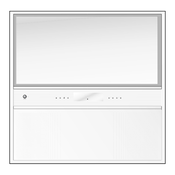
- Page 10 Front panel ¥ RE/RL-39NZ40 series RT-39NZ40 series TV/AV MENU INDEX TV/AV MENU INDEX 2 3 4 5 (Side panel) 1. MAIN POWER (Volume Down/Up) switches the set on or off. adjusts the volume. adjusts menu settings. 2. TV/AV (Programme Up/Down) selects TV or AV mode.
-
Page 11: Adjustment Instructions
ADJUSTMENT INSTRUCTIONS Raster Slope/Focus 1th Adjustment 45mm 1. Preliminary steps 1) Receive the EU 05 CH signal. 2) Adjustment Lens focus and Electric provisionally. 3) Set the convergence on RESET. a.Adjustment mode:Press the SVC key and then press the /M key. b.Data reset : Press 5 KEY and then OK key. - Page 12 2. Adjustment 3) Reset the data in convergence adjustment mode,quit the mode. 1) Operate adjustment about Red,Green,Blue centering Adjustment Mode : Press the ÒSVCÓ key and then /M key. magnet. Data reset : Press the Ò5Ó key and then OK key. 2) SGS-THOMSON Convergence assy Adjustment mode cancellation :Press the /M key.
- Page 13 12) L-VL(Lower Vertical Linearity) 2. G-lens Adjustment Adjust vertical linearity of lower screen 1) Rotate the lens until the chromatic haze changes from blue to red. 13) VL (Vertical Linearity) 2) Viewing the all screen, in no case of the chromatic aberration Adjust the top/bottom size of circle to be same in the EU 05CH.
- Page 14 Convergence Adjustment 4. Auto convergence Convergence is based on the auto adjustment using PC and 1. Preliminary steps Camera while applying the THOMSON convergence Assy and if need,adjust manually like below method. This adjustment should be performed after warming up 60 minutes.
- Page 15 3)If not,press SVC key on R/C to enter adjustment mode and then press the YELLOW key to move into ÔSERVICE Auto-Convergence Check ADJUSTMENT 5Õ 1)Check the Auto-Convergence in PAL/NTSC mode separating. 4)Adjust M-HOR and M-VER so that left/right space to be 2)Press the SVC key on R/C for adjustment and press the symmetry.
- Page 16 Convergence Adjustment Mode * 39Ó 16:9 WIDE MODEL - SVC -> / / M -> MENU <NTSC mode> <PAL mode> * This Mode is for engineering. So,donÕt change before permission from Design Department. 0.AC POSITION READ : Distance data(After auto convergence 12,15 12,12 10,26...
- Page 17 SVC Adjustment mode & Initial data Range Menu Description Default DC-TR DC transmission control 1. White Blalane adjustment data (IC:CXA2100) LRGB2 RGB2 output level control Menu Description Range Default DL-PA DElay Line switching Red Drive SHPF0 Sharpness f0 Green Drive CB-F1 INput1 CB signal DC Offset Blue Drive...
- Page 18 6.OPTION Data Adjustment Range Description Default Range Description Default 1: With Teletext 200 PRO 1: 200 Program(CHINA Only) TEXT 0: Without Teletext(CHINA) 0: 100 Program 1: RF 54% Modulation INput 1: With TURBO Search TSEAR option3 SCART 0: RF 100% Modulation INput 0: Without TURBO Search 1: China+AUST.Channel Table I/II SV...
- Page 19 State Language Function Default English 0:ENG Only 1:EU 5EA English/German/French/Italy/Spanish 2:EU ETC Pol./Hungary/Czecho/Russia/Eng 3:PARSI English/Parsi LANG 4:ARAB URDU English/French/Arab+Urdu 5:English+Hindi English/Hindi 6:English+I+M+V English/Indonesian/Malaysian/Vietnamese English/Thai 7:English+THAI 8:English+China English/China 0:West Europe English/French/Swedish/Czech/German/Spanish/Italian 1:East Europe Polish/French/Swedish/Czech/German/Slovenian/Italian/Rumanian option4 2:Turkey EU English/French/Swedish/Turkish/German/Spanish/Italian 3:EAST EU2 English/Hungarian/Serbian/Czech/German/Polish/Spanish/Italian/ Rumanian 4:Cyrillic 1 5:Cyrillic 2...
-
Page 20: Trouble Shooting
TROUBLE SHOOTING - 20 -... - Page 21 - 21 -...
- Page 22 - 22 -...
- Page 23 - 23 -...
- Page 24 - 24 -...
- Page 25 - 25 -...
- Page 26 - 26 -...
- Page 27 - 27 -...
-
Page 28: Block Diagram
BLOCK DIAGRAM SIGNAL(RT -) - 28 -... - Page 29 BLOCK DIAGRAM SIGNAL(RE/RL-) - 29 -...
- Page 30 BLOCK DIAGRAM IC401,406 B+(115V) B+(105V ) KIA358 H OUT H-DRIVE DUMMY H-DF H-DRIVE Q402 H-DY TRANS Q403 IRFIBC206 T405 T401 2SC5446 FOCUS FOCUS PACK HV OUT HVDRIVE HV DRIVE Q413 TRANS T403 BLOCK Q416 IRFIBC20G T402 2SD1887 DYNAMIC FOCUS PWM PULSE P411 9V p-p Q433...
- Page 31 MEMO - 31 -...
-
Page 32: Printed Circuit Board
PRINTED CIRCUIT BOARD MAIN1 - 32 -... - Page 33 COMPONENT LOCATION GUIDE(MAIN1) J215 ..G5 Q503 ..E3 R110 ..G5 R621 ..D2 C001..A5 C202 ..G4 E007 ..F1 J39 ..C2 J110 ..D4 C002..B5 R111 ..G5 R622..F1 C203..F3 E008 ..F1 J40 ..B2 J111 ..G3 J216 ..G4 Q600..F2 C003..B5 C205 ..G4 F001 ..B5 J41 ..B1 J112 ..G3 J217 ..G4 Q601 ..D2...
- Page 34 MAIN2 (DEF) - 34 -...
- Page 35 COMPONENT LOCATION GUIDE(DEF) C401..A2 C480..F1 E424 ..F1 G457 ..D1 J458..F2 P409B ..C2 R435..E1 R40D ..E5 C481..E2 E425..A1 G458 ..D1 J459 ..C2 P409C ..C2 R436..E1 R40E ..E5 C402..A2 IC401..E2 J460..F2 P409D ..C2 R437..E4 R40F ..E5 C403 ..D3 C482..E2 E426..B1 P410A..F5 R438..F4 R40G..E5 C404 ..C1 C484..B3...
- Page 36 SMPS - 36 -...
- Page 37 COMPONENT LOCATION GUIDE(SMPS) J850..F5 P810B ..G1 R863 ..G5 C801 ..D5 C868 ..C4 D837..F4 G804..F4 G862..F4 IC801..B3 G863..F4 IC802 ..C3 J851..F5 P811A ..G2 R864 ..G4 C802 ..D5 C869 ..C3 D839 ..G2 G805 ..B5 R865 ..G4 G806 ..B4 G865..F4 IC803 ..C1 J854..F2 P812A..F1 C803..B5 C870..F3...
- Page 38 CONV-OUT - 38 -...
- Page 39 CONTROL POWER S/W PRE-AMP SIDE AV - 39 -...
- Page 40 INTERFACE CONTROL CONVERGENCE INTERFACE - 40 -...
- Page 41 CONVERGENCE (TOP) CONVERGENCE (BOTTOM) - 41 -...
- Page 42 MICOM (TOP) MICOM (BOTTOM) - 42 -...
- Page 43 100HZ (TOP) 100HZ (BOTTOM) - 43 -...
- Page 44 AV (TOP) AV (BOTTOM) - 44 -...
- Page 45 AUTO CVG SENSOR(BOTTOM) AUTO CVG SENSOR(TOP) - 45 -...
- Page 46 HARMONICS - 46 -...
- Page 47 MEMO - 47 -...
-
Page 48: Exploded View
EXPLODED VIEW(RE/RL-39NZ40RB) - 48 -... -
Page 49: Exploded View Parts List
The components identified by mark critical for safety. REPLACEMENT PARTS LIST Replace only with part number specified. LOCA. NO PART NO DESCRIPTION LOCA. NO PART NO DESCRIPTION IC408 0IKE358000A IC, KIA358P DIP8 DUAL OP-AMP BK IC409 0IKE780500Q IC, KIA7805API 3P TO-220 ST REGULATOR 5V DLA801 0ISK100300A IC, SLA1003 SIP12 BK DIODE MODULE LF816... - Page 50 LOCA. NO PART NO DESCRIPTION LOCA. NO PART NO DESCRIPTION Q002 0TR319809AA TR, KTC3198(KTC1815) KEC TP TO92 50V 150MA Q203 0TR387500AA TR, CHIP 2SC3875S(ALY) KEC Q003 0TR319809AA TR, KTC3198(KTC1815) KEC TP TO92 50V 150MA Q2030 0TR387500AA TR, CHIP 2SC3875S(ALY) KEC 0TR830009BA 0TR387500AA Q003...
- Page 51 LOCA. NO PART NO DESCRIPTION LOCA. NO PART NO DESCRIPTION Q501 0TR387500AA TR, CHIP 2SC3875S(ALY) KEC 0TR319809AA TR, KTC3198(KTC1815) KEC TP TO92 50V 150MA Q502 0TR319809AA TR, KTC3198(KTC1815) KEC TP TO92 50V 150MA 0TR319809AA TR, KTC3198(KTC1815) KEC TP TO92 50V 150MA 0TR150400BA 0TR319809AA Q502...
- Page 52 LOCA. NO PART NO DESCRIPTION LOCA. NO PART NO DESCRIPTION D446 0DS113379BA DIODE, 1SS133 T-72 TP ROHM KOREA DO34 90V - D903G 0DR210009AC DIODE,DO35 200V 0.2A 1A 50SEC 100A D480 0DD140009AA DIODE, E/EO-TMD 40V 1.5A 40A 0.2US 5MA D903R 0DR210009AC DIODE,DO35 200V 0.2A 1A 50SEC 100A 0DD060009AC 0DR210009AC...
- Page 53 For Capacitor & Resistors, CC, CX, CK, CN : Ceramic RD : Carbon Film the charactors at 2nd and 3rd CQ : Polyestor RS : Metal Oxide Film digit in the P/No. means as CE : Electrolytic RN : Metal Film follows;...
- Page 54 For Capacitor & Resistors, CC, CX, CK, CN : Ceramic RD : Carbon Film the charactors at 2nd and 3rd CQ : Polyestor RS : Metal Oxide Film digit in the P/No. means as CE : Electrolytic RN : Metal Film follows;...
- Page 55 For Capacitor & Resistors, CC, CX, CK, CN : Ceramic RD : Carbon Film the charactors at 2nd and 3rd CQ : Polyestor RS : Metal Oxide Film digit in the P/No. means as CE : Electrolytic RN : Metal Film follows;...
- Page 56 For Capacitor & Resistors, CC, CX, CK, CN : Ceramic RD : Carbon Film the charactors at 2nd and 3rd CQ : Polyestor RS : Metal Oxide Film digit in the P/No. means as CE : Electrolytic RN : Metal Film follows;...
- Page 57 The components identified by mark For Capacitor & Resistors, CC, CX, CK, CN : Ceramic RD : Carbon Film the charactors at 2nd and 3rd CQ : Polyestor RS : Metal Oxide Film critical for safety. digit in the P/No. means as CE : Electrolytic RN : Metal Film Replace only with part number specified.
- Page 58 For Capacitor & Resistors, CC, CX, CK, CN : Ceramic RD : Carbon Film the charactors at 2nd and 3rd CQ : Polyestor RS : Metal Oxide Film digit in the P/No. means as CE : Electrolytic RN : Metal Film follows;...
- Page 59 COIL,CHOKE 82UH PHY TURN P401A 387-A08A CONNECTOR ASSEMBLY 8P 2.5MM 100MM HB L815 150-C02F COIL,CHOKE 82UH PHY TURN P401B 366-921G CONNECTOR (CIRC),WAFER 2.5MM 8P GILG LG 150-C02F 6631V25A04A L816 COIL,CHOKE 82UH PHY TURN P402A CONNECTOR ASSEMBLY 14P 2.5MM 100MM HB L817 150-C02F...
- Page 60 For Capacitor & Resistors, CC, CX, CK, CN : Ceramic RD : Carbon Film the charactors at 2nd and 3rd CQ : Polyestor RS : Metal Oxide Film digit in the P/No. means as CE : Electrolytic RN : Metal Film follows;...
- Page 61 For Capacitor & Resistors, CC, CX, CK, CN : Ceramic RD : Carbon Film the charactors at 2nd and 3rd CQ : Polyestor RS : Metal Oxide Film digit in the P/No. means as CE : Electrolytic RN : Metal Film follows;...
- Page 62 For Capacitor & Resistors, CC, CX, CK, CN : Ceramic RD : Carbon Film the charactors at 2nd and 3rd CQ : Polyestor RS : Metal Oxide Film digit in the P/No. means as CE : Electrolytic RN : Metal Film follows;...
- Page 63 The components identified by mark For Capacitor & Resistors, CC, CX, CK, CN : Ceramic RD : Carbon Film the charactors at 2nd and 3rd CQ : Polyestor RS : Metal Oxide Film critical for safety. digit in the P/No. means as CE : Electrolytic RN : Metal Film Replace only with part number specified.
- Page 64 10K OHM 1/6 W 5% TA52 SW800 140-289A SWITCH,PUSHPOWER SDDF3PASP013 LG C&D R925G 0RD1002F609 10K OHM 1/6 W 5% TA52 SWT1 140-313B SWITCH,TACT 2LEAD 160G(TA) LG C&D NON 180-C02P 140-313B R926B 220OHM 1/2 W 5% TA52 SWT2 SWITCH,TACT 2LEAD 160G(TA) LG C&D NON R926G 180-C02P...
- Page 65 LOCA. NO PART NO DESCRIPTION LOCA. NO PART NO DESCRIPTION F208 6210TCE001G FILTER(CIRC),EMC HH1M3216501 3216MM R/TP L2007 6210TCT002B FILTER(CIRC),EMC ACB2012M300T TDK , CHIP F209 6210TCE001G FILTER(CIRC),EMC HH1M3216501 3216MM R/TP L2008 6210TCT002B FILTER(CIRC),EMC ACB2012M300T TDK , CHIP 6210TCE001G 6210TCT002B F210 FILTER(CIRC),EMC HH1M3216501 3216MM R/TP L2009 FILTER(CIRC),EMC ACB2012M300T TDK , CHIP F211...
- Page 66 SPARK GAP, 300V 20% AXIAL TYPE 5MM SG903R 6918VAX002D SPARK GAP, 300V 20% AXIAL TYPE 5MM ACCESSORIES 3828VA0382B MANUAL,OWNERS DG LG GE/FR NE/EN 089B TX 3828VA0382D MANUAL,OWNERS UK/WTY LG EN 089B TX 026F 3828VA0382G MANUAL,OWNERS ES LG SP/PO 089B TX 3828VA0382K...
- Page 67 BRACKET, PRT ASSY R LENS+COUPLER+CPT 4810V00833B BRACKET, PRT ASSY G LENS+COUPLER+CPT 4810V00833C BRACKET, PRT ASSY B LENS+COUPLER+CPT 120-D38E SPEAKER,MID-RANGE LG FOSTER 8 OHM 15/25W 87DB 12 4810V00697A BRACKET,SPEAKER RN-39NZ40 SP02PA HIPS 51SF . 6150Z-1100B DY(DEFLECTION YOKE),DY 38 KHZ 07 LGPD PRT 6410VBH007B...
- Page 68 P/NO:3854VA0094D-S1(1/2) 2003.03.13...
- Page 69 P/NO:3854VA0094D-S1(2/2) 2003.03.13...
- Page 70 P/NO:3854VA0094D-S2(1/2) 2003.03.13...
- Page 71 P/NO:3854VA0094D-S2(2/2) 2003.03.13...
- Page 72 P/NO:3854VA0094D-S3 2003.03.13...
- Page 73 SVC. SHEET : 3854V A0094D-S1 3854V A0094D-S2 3854V A0094D-S3...
Need help?
Do you have a question about the RE-39NZ40RB and is the answer not in the manual?
Questions and answers