Sony XR-C5300X Service Manual
Fm/mw/sw and fm/am cassette car stereo
Hide thumbs
Also See for XR-C5300X:
- Operating instructions manual (24 pages) ,
- Service manual (42 pages) ,
- Installation/connections manual (14 pages)
Table of Contents
Advertisement
XR-C5300X/C5305/C5600X
SERVICE MANUAL
US Model
Canadian Model
XR-C5300X/C5305
E Model
XR-C5600X
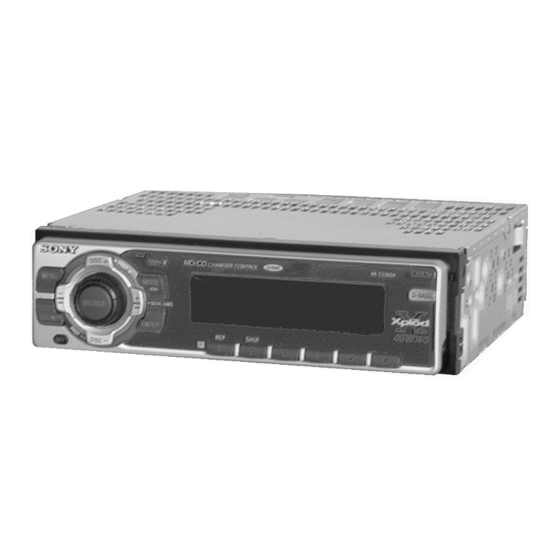
Photo: XR-C5300X
Model Name Using Similar Mechanism
XR-C5100
SPECIFICATIONS
Tape Transport Mechanism Type
MG-25F-136
FM/AM CASSETTE CAR STEREO
XR-C5300X/C5305
FM/MW/SW CASSETTE CAR STEREO
XR-C5600X
MICROFILM
Advertisement
Table of Contents

Related Manuals for Sony XR-C5300X


Summary of Contents for Sony XR-C5300X
- Page 1 XR-C5300X/C5305/C5600X SERVICE MANUAL US Model Canadian Model XR-C5300X/C5305 E Model XR-C5600X Photo: XR-C5300X Model Name Using Similar Mechanism XR-C5100 SPECIFICATIONS Tape Transport Mechanism Type MG-25F-136 FM/AM CASSETTE CAR STEREO XR-C5300X/C5305 FM/MW/SW CASSETTE CAR STEREO XR-C5600X MICROFILM...
-
Page 2: Table Of Contents
TABLE OF CONTENTS Flexible Circuit Board Repairing • Keep the temperature of the soldering iron around 270 ˚C dur- ing repairing. 1. SERVICE NOTE ............. 2 • Do not touch the soldering iron on the same conductor of the circuit board (within 3 times). 2. -
Page 3: General
SECTION 2 This section is extracted from instruction manual. GENERAL... -
Page 13: Disassembly
SECTION 3 DISASSEMBLY Note: Follow the disassembly procedure in the numerical order given. SUB PANEL, MECHANISM DECK (MG-25F-136) 0 Mechanism deck 9 Screw (MG-25F-136) (PTT2.6 × 6) 8 Connector(CN351) 7 Flexible flat cable (CNP301) 5 Sub panel ass'y 3 Screw (PTT2.6 ×... -
Page 14: Assembly Of Mechanism Deck
SECTION 4 ASSEMBLY OF MECHANISM DECK Note: Follow the assembly procedure in the numerical order given. 7 Holder the hanger by bending the claw. HOUSING 5 Fit projection on C part. 1 Install the catch to the hanger. 2 Install the hanger onto two claws of the housing. - Page 15 LEVER (LDG-A)/(LDG-B) shaft A shaft A shaft B shaft B shaft C 1 Fit the lever (LDG-A) on shafts A – C and install it. 3 type-E stop ring 2.0 2 Fit the lever (LDG-B) on shafts A and B and install it.
- Page 16 GUIDE (C) 2 guide (C) 1 three claws MOUNTING POSITION OF CAPSTAN/REEL MOTOR (M901) two precision screws (P2 × 2) capstan/reel motor (M901) 30˚...
-
Page 27: 7-8. Ic Pin Function
7-8. IC PIN FUNCTION • IC501 MASTER MICRO COMPUTER (MN101C49KTA) (MAIN Board) Pin No. Pin Name Function Reference voltage (– side) of AD conversion Connect to power ground if no problems VREF — such as noise FM/AM common signal meter A/D conversion input terminal AM (MW:SW:LW), FM S meter voltage detection terminal FM AGC A/D conversion input terminal FMAGC... - Page 28 Pin No. Pin Name Function Key input acknowledge Acknowledge signal input terminal to accept the function and eject key from the power off state The A/D conversion input power supply is off to save power in the power off state, and KEYACK key inputs cannot be accepted by A/D This terminal can therefore determine if function keys have been pressed even in the...
- Page 29 Pin Name Function Pin No. Serial clock input UNICLI UNI-LINK serial interface clock input terminal Serial data output UNISO UNI-LINK serial interface data output terminal Serial data input UNISI UNI-LINK serial interface data input terminal Serial clock output UNICKO UNI-LINK serial interface clock output terminal C bus serial data input/output I2C_SIO Serial interface with electronic volume IC, TUX-020...
- Page 30 Pin Name Function Pin No. 70 to 73 Not used EEPROM communication terminal E2P_SIO EEPROM data input/output terminal EEPROM communication terminal E2P_CKO EEPROM clock output terminal Not used AM filter control terminal SWSHIFT Outputs “L”during 2.94 to 5.585, 14.125 to 18.135 MHz during SW reception, and outputs “H”...
- Page 31 Pin No. Pin Name Function DAVSS NS_MASK Not used DAVDD...
-
Page 32: Exploded Views
SECTION 8 EXPLODED VIEWS NOTE: • Items marked “*” are not stocked since they • Abbreviation • -XX and -X mean standardized parts, so they CND: Canadian model may have some difference from the original are seldom required for routine service. Some one. - Page 33 (2) FRONT PANEL SECTION not supplied (KEY board) LCD901 Ref. No. Part No. Description Remark Ref. No. Part No. Description Remark 3-040-980-01 BUTTON (SOURCE) * 60 3-040-997-01 PLATE (LCD), GROUND 3-040-981-01 KNOB (VOL)(C5300X,C5305) * 61 3-041-371-02 SHEET (REFLECTOR) 3-040-981-11 KNOB (VOL)(C5600X) * 62 3-040-993-01 PLATE (LCD), LIGHT GUIDE 3-041-005-11 BUTTON (D)
- Page 34 (3) MECHANISM DECK SECTION (MG-25F-136) HP901 M901 Ref. No. Part No. Description Remark Ref. No. Part No. Description Remark A-3291-667-A CLUTCH (FR) ASSY 3-933-346-01 CATCHER * 152 3-019-130-01 LEVER (LDG-A) 3-933-344-01 GUIDE (C) * 153 3-019-131-01 LEVER (LDG-B) 3-014-798-01 SCREW (HEAD), SPECIAL 3-020-539-01 SPRING (LD-1), TENSION 3-364-151-01 WASHER 3-020-540-01 SPRING (LD-2), TENSION...
-
Page 35: Electrical Parts List
SECTION 9 MAIN ELECTRICAL PARTS LIST Note: • Due to standardization, replacements in the parts • SEMICONDUCTORS When indicating parts by reference list may be different from the parts specified in In each case, u: µ , for example: number, please include the board uA...: µ... - Page 36 MAIN Ref. No. Part No. Description Remark Ref. No. Part No. Description Remark C301 1-124-234-00 ELECT 22uF C753 1-164-506-11 CERAMIC CHIP 4.7UF C755 1-124-233-11 ELECT 10UF 20.00% 16V C302 1-131-353-00 TANTALUM 10uF C756 1-164-506-11 CERAMIC CHIP 4.7UF C303 1-163-251-11 CERAMIC CHIP 100PF 5.00% 50V C304...
- Page 37 MAIN Ref. No. Part No. Description Remark Ref. No. Part No. Description Remark < IC > Q353 8-729-900-53 TRANSISTOR DTC114EKA-T146 IC301 8-752-079-78 IC CXA2509AQ-T4 Q354 8-729-106-60 TRANSISTOR 2SB1132-T100-R IC331 8-759-653-27 IC TDA7402TR Q551 8-729-027-23 TRANSISTOR DTA114EKA-T146 IC351 8-759-527-33 IC LB1930M-TLM Q571 8-729-120-28 TRANSISTOR 2SC2412K-T-146-QR IC501...
- Page 38 MAIN Ref. No. Part No. Description Remark Ref. No. Part No. Description Remark R304 1-216-077-00 RES-CHIP 1/10W R558 1-216-033-00 METAL CHIP 1/10W R305 1-216-001-00 METAL CHIP 1/10W R560 1-216-089-00 RES-CHIP 1/10W (C5600X) R306 1-216-105-00 RES-CHIP 220K 1/10W R561 1-216-073-00 METAL CHIP 1/10W R331 1-216-001-00 METAL CHIP...
- Page 39 MAIN Ref. No. Part No. Description Remark Ref. No. Part No. Description Remark < THERMISTOR > LED904 8-719-061-16 DIODE CL-190SR-CD-T (C5300X,C5600X) LED910 8-719-078-19 DIODE LWA673 TH501 1-803-350-21 THERMISTOR, POSITIVE LED911 8-719-078-19 DIODE LWA673 < TUNER > LED912 8-719-078-19 DIODE LWA673 LED913 8-719-078-19 DIODE LWA673 A-3220-738-A TUNER UNIT (TUX-020) LED914 8-719-078-19 DIODE LWA673...
- Page 40 Ref. No. Part No. Description Remark Ref. No. Part No. Description Remark R904 1-216-651-11 METAL CHIP 0.5% 1/10W R971 1-216-815-11 METAL CHIP 1/16W R905 1-216-655-11 METAL CHIP 1.5K 0.5% 1/10W R972 1-216-864-11 METAL CHIP 1/16W R973 1-216-815-11 METAL CHIP 1/16W R906 1-216-655-11 METAL CHIP 1.5K...
- Page 41 Ref. No. Part No. Description Remark Ref. No. Part No. Description Remark ACCESSORIES & PACKING MATERIALS ******************************** 1-418-812-11 REMOTE COMMANDER (RM-X91) (C5300X/C5305) 1-476-015-11 REMOTE COMMANDER (RM-X74)(C5600X) 3-044-361-11 MANUAL, INSTRUCTION (ENGLISH)(C5300X/C5305) 3-044-361-21 MANUAL, INSTRUCTION (FRENCH)(C5300X:CND/C5305:CND) 3-044-361-31 MANUAL, INSTRUCTION (ENGLISH, SPANISH, CHINESE)(C5600X) 3-044-362-11 MANUAL, INSTRUCTION, INSTALL (ENGLISH, FRENCH)(C5300X, C5305) 3-044-362-21 MANUAL, INSTRUCTION, INSTALL...
- Page 42 XR-C5300X/C5305/C5600X Sony Corporation 9-870-102-11 2000B097035-1 Mobile Electronics Division Company Printed in Singapore © 2000. 2 Published by General Engineering Dept.
Need help?
Do you have a question about the XR-C5300X and is the answer not in the manual?
Questions and answers