Table of Contents
Advertisement
Quick Links
SERVICE MANUAL
Refer to RM-X2S/X3S SERVICE MANUAL (9-960-039-∏)
issued previously for information of remote commander
(RM-X2S) supplied with this set.
Dolby noise reduction manufactured under license
from Dolby Laboratories Licensing Corporation.
"DOLBY" and the double-D symbol a are trademarks
of Dolby Laboratories Licensing Corporation.
Cassette player section
Tape track
4-track 2-channel stereo
Wow and flutter
0.08% (WRMS)
Frequency response
30 – 20,000 Hz
Signal-to-noise ratio
Cassette type
Dolby B NR
TYPE II, IV
67 dB
TYPE I
64 dB
Tuner section
FM *
Turning range
65.0 – 74.0 MHz
(at 30 kHz step)
87.5 – 108.0 MHz
(at 50 kHz step)
Aerial terminal
External aerial connector
Intermediate frequency 10.7 MHz
Usable sensitivity
8 dBf
Selectivity
75 dB at 400 kHz
Signal-to-noise ratio
65 dB (stereo),
68 dB (mono)
Harmonic distortion at 1 kHz
0.5% (stereo),
0.3% (mono)
Separation
35 dB at 1 kHz
Frequency response
30 – 15,000 Hz
Capture ratio
2 dB
* There are the numerical values mesured at 87.5 – 108.0 MHz.
MW/LW
Tuning range
MW: 531 – 1,602 kHz
LW: 153 – 281 kHz
Aerial terminal
External aerial connector
Intermediate frequency 10.71 MHz/450 kHz
Sensitivity
MW: 30 µV
LW: 50 µV
MICROFILM
XR-C543SP
SPECIFICATIONS
Power amplifier section
Outputs
Speaker impedance
Maximum power output 35 W × 4 (at 4 ohms)
Dolby NR off
General
61 dB
Outputs
58 dB
Tone controls
Power requirements
Dimensions
Mounting dimensions
Mass
Supplied accessories
Design and specifications are subject to change without notice.
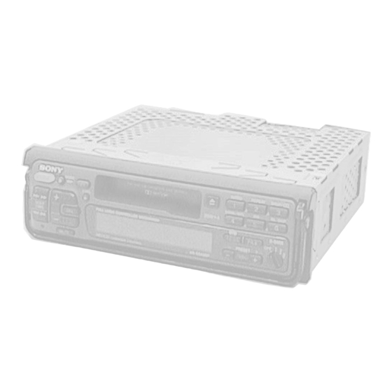
FM/MW/LW CASSETTE CAR STEREO
East European Model
Model Name Using Similar Mechanism
Tape Transport Mechanism Type
Speaker outputs
(sure seal connectors)
4 – 8 ohms
Power amplifier control
lead/Power aerial control
lead/Telephone mute
control lead
Line out (2)
Bass ± 8 dB at 100 Hz
Treble ± 8 dB at 10 kHz
12 V DC car battery
(negative ground)
Approx. 188 × 58 × 183 mm (w/h/d)
Approx. 182 × 53 × 164 mm (w/h/d)
Approx. 1.6 kg
Parts for installation and connections (1 set)
Rotary commander
RM-X2S
XR-C553SP
MG-52A-135
Advertisement
Table of Contents

Related Manuals for Sony XR-C543SP


Summary of Contents for Sony XR-C543SP
- Page 1 XR-C543SP SERVICE MANUAL East European Model Refer to RM-X2S/X3S SERVICE MANUAL (9-960-039-∏) issued previously for information of remote commander (RM-X2S) supplied with this set. Dolby noise reduction manufactured under license Model Name Using Similar Mechanism XR-C553SP from Dolby Laboratories Licensing Corporation.
-
Page 2: Table Of Contents
TABLE OF CONTENTS SERVICING NOTES GENERAL Flexible Circuit Board Repairing • Keep the temperature of the soldering iron around 270 ˚ C dur- Location of Controls ............3 Installation ............... 4 ing repairing. • Do not touch the soldering iron on the same conductor of the Connections .............. - Page 3 SECTION 1 This section is extracted from instruction manual. GENERAL – 3 –...
- Page 4 – 4 –...
- Page 5 – 5 –...
- Page 6 – 6 –...
- Page 7 – 7 –...
-
Page 8: Disassembly
SECTION 2 DISASSEMBLY Note: Follow the disassembly procedure in the numerical order given. COVER 1 two screws (PTT2.6 × 6) 3 Remove the cover toward direction A . COLLAR (A), HANDLE ASS’Y 3 screw (PTT2.6 × 6) 3 screw 1 Seven claws 4 handle ass’y (PTT2.6 ×... - Page 9 FRONT PANEL ASS’Y 1 two claws 1 three claws 2 front panel ass’y MECHANISM DECK 3 two screws (PTT2.6 × 6) 5 mechanism deck 1 connector (CNP331) 4 front chassis 2 flexible board (CNP301) 3 three screws (PTT2.6 × 6) –...
- Page 10 POWER BOARD 3 power board 1 three screws (PTT2.6 × 8) 2 two connectors (CNJ400,401) MAIN BOARD 1 two ground point screws 4 antenna cable 2 ground point screw 3 main board – 10 –...
-
Page 11: Assembly Of Mechanism Deck
SECTION 3 ASSEMBLY OF MECHANISM DECK Note: Follow the assembly procedure in the numerical order given. ALIGNMENT OF FRONT SWITCH 1 Align ¢ mark on the rotary switch hole the position shown in the figure. chassis (S) ass’y 2 Align hole in the gear (LDG-D) with the position shown in the figure. - Page 12 CHASSIS (S) ASS’Y 2 screw (PS2 × 4) 2 screw (PS2 × 4) 1 chassis (S) ass’y LEVER (MODE) 1. Align ¢ mark on the rotary switch with hole in the lever (mode). 2. Fit on positions A , B and C and install the lever (mode).
- Page 13 LEVER (PINCH SELECTION) 1 Align. 2 lever (pich selection) HEAD PLATE ASS’Y 5 step screw (HP) 5 step screw (HP) 3 Press the ATS lever. 2 Fit shaft in groove. 4 Position the head plate sub ass’y as shown in the figure. ATS lever 1 Fit in groove.
- Page 14 LEVER (PINCH) ASS’Y 2 two polyethylene washers 1 Fit shaft of the lever (Pinch) ass’y in hole on the chassis (M) ass’y and install the lever (pinch) ass’y. shaft shaft shaft A 3 Install the spring (pinch press) to shaft A . Set the ends of spring to B and C .
- Page 15 ARM (SUCTION) 2 Move the arm (suction) in the arrow direction and fit on projection. 1 Fit the arm (suction) on the shaft. projection LEVER (LDG-A) / (LDG-B) shaft A shaft A shaft B shaft C shaft B 1 Fit the lever (LDG-A) 3 two type-E stop ring 2.0 on shaft A –...
- Page 16 GEAR (LDG-FT) 1 gear (LDG-A) 6 polyethylene washer 5 gear (LDG-FT) 2 tension spring (lever LDG) gear (LDG-D) hole 3 Move the lever (LDG-B) in the arrow direction. gear (LDG-A) gear (LDG-FB) 4 Align hole in the gear (LDG-D) with ¢...
-
Page 17: Mechanical Adjustments
SECTION 4 SECTION 5 MECHANICAL ADJUSTMENTS ELECTRICAL ADJUSTMENTS 1. Clean the following parts with a denatured-alcohol-moistened TEST MODE swab: This set have the test mode function. In the test mode, FM Auto playback head pinch roller Scan/Stop Level and MW Auto Scan/Stop Level adjustments can rubber belt capstan be performed easier than it in ordinary procedure. -
Page 18: Tape Deck Section
See the adjustment location from on page 21 for the TUNER SECTION 0 dB=1 µV adjustment. Cautions during repair When the tuner unit is defective, replace it by a new one be- TAPE DECK SECTION 0 dB=0.775 V cause its internal block is difficult to repair. Tape Speed Adjustment FM Auto Scan/Stop Level Adjustment Procedure:... - Page 19 FM Stereo Separation Adjustment MW Auto Scan/Stop Level Adjustment Setting: Setting: SOURCE button: FM SOURCE and MODE button: MW FM RF signal level meter generator 30 Ω 15 pF antenna jack 10 k Ω 65 pF – AM RF signal generator LINE OUT Carrier frequency : 98.0 MHz...
- Page 20 FM Polar VCO Adjustment FM Polar Pilot Adjustment Setting: Setting: SOURCE button: FM SOURCE button: FM antenna jack antenna jack FM RF signal FM RF signal generator generator Carrier frequency : 69.5 MHz (FM2: 3CH) Carrier frequency : 69.5 MHz (FM2: 3CH) Output level : 60 dB (1 mV) Output level...
- Page 21 Adjustment Location: – SET UPPER VIEW – Tape Speed Adjustment RV221 (R-CH) DOLBY Level Adjustment RV121 (L-CH) RV1 MW Auto Scan/Stop Level Adjustment RV2 FM Auto Scan/Stop Level Adjustment RV4 FM Stereo Separation Adjustment L401 FM Polar Pilot Adjustment RV401 ...
-
Page 22: Diagrams
Serial data transfer clock signal output to the bus interface (IC571) (for SONY bus) BUS-ON Bus on/off control signal output to the bus interface (IC571) (for SONY bus) “L”: bus on SYS-RST Reset signal output to the bus interface (IC571) (for SONY bus) “L”: reset... - Page 23 Pin No. Pin Name Function Loading/tape operation motor (M902) control signal output to the MM1322XF (IC651) LM_LOD (For the loading direction and forward side operation) *1 Loading/tape operation motor (M902) control signal output to the MM1322XF (IC651) LM_EJ (For the eject direction and reverse side operation) *1 Forward/reverse direction control signal output to the CXA2510Q (IC101) N/R_OUT “L”: forward direction, “H”: reverse direction...
- Page 24 Pin No. Pin Name Function XT_OUT Sub system clock output terminal Not used this set (open) XT_IN Sub system clock input terminal Not used this set (fixed at “L”) AVDD — Power supply terminal (+5V) (for A/D converter) AVREF Reference voltage input terminal (+5V) (for A/D converter) KEYIN Key input terminal (A/D input) KEYIN1...
- Page 31 • IC Block Diagrams IC301 LC75373ED IC31 BU2624F-E2 IC651 MM1322XFBE XOUT – LFIN – REFERENCE 8 OUT2 – PHASE – DIVIDER DETECT LFOUT – LSELO LROUT – – – OUT1 VREF CONTROL FMIN SHIFT DECODER LATCH CONTROL REGISTER – MAIN AMIN COUNT –...
-
Page 32: Exploded Views
SECTION 7 EXPLODED VIEWS NOTE: • -XX and -X mean standardized parts, so they • Items marked “*” are not stocked since they may have some difference from the original are seldom required for routine service. Some one. delay should be anticipated when ordering •... - Page 33 Remark 3-009-301-01 BUTTON (BASS) 3-935-003-01 SPRING, TORSION 3-009-299-01 BUTTON (L2) (+.–) * 63 3-010-282-01 PLATE (LCD), GROUND 3-904-194-01 EMBLEM (NO. 2.5), SONY * 64 3-009-305-11 SHEET (REFLECTOR) 3-012-576-01 BUTTON (RESET) * 65 3-009-302-01 PLATE (LCD), LIGHT GUIDE 3-009-300-01 BUTTON (SOURCE)
- Page 34 (3) MECHANISM DECK SECTION (MG-52A-135) M901 Ref. No. Part No. Description Remark Ref. No. Part No. Description Remark PL902 1-517-633-11 LAMP, PILOT 3-928-675-01 BELT (52) 3-933-346-01 CATCHER * 102 3-928-673-01 LEVER (LDG-A) 3-933-344-01 GUIDE (C) 3-928-674-01 LEVER (LDG-B) 3-341-753-11 WASHER, POLYETHYLENE 3-933-341-01 SPRING (LEVER LDG), TENSION 3-933-335-01 GEAR (LDG-FT) 3-928-671-01 HOUSING...
- Page 35 (4) MECHANISM DECK SECTION-2 (MG-52A-135) HP901 S901 M902 Ref. No. Part No. Description Remark Ref. No. Part No. Description Remark * 166 X-3371-712-1 PLATE SUB ASSY, HEAD X-3371-710-1 CHASSIS (S) ASSY 3-364-151-01 WASHER * 168 X-3371-701-1 CHASSIS (M) SUB ASSY (A) 3-933-337-01 SPRING (B-T-R), CONE COIL 3-701-437-01 POLY-SLIDER (A) X-3371-707-1 CLUTCH (PLAY) ASSY...
-
Page 36: Electrical Parts List
SECTION 8 CONTROL ELECTRICAL PARTS LIST NOTE: • Due to standardization, replacements in the • Items marked “*” are not stocked since they When indicating parts by reference parts list may be different from the parts speci- are seldom required for routine service. number, please include the board. - Page 37 CONTROL MAIN Ref. No. Part No. Description Remark Ref. No. Part No. Description Remark R961 1-216-037-00 METAL CHIP 1/10W 1-163-251-11 CERAMIC CHIP 100PF R962 1-216-033-00 METAL CHIP 1/10W 1-163-237-11 CERAMIC CHIP 27PF R963 1-216-029-00 METAL CHIP 1/10W 1-163-104-00 CERAMIC CHIP 30PF R964 1-216-025-00 METAL CHIP...
- Page 38 MAIN Ref. No. Part No. Description Remark Ref. No. Part No. Description Remark C331 1-163-038-00 CERAMIC CHIP 0.1uF C609 1-126-157-11 ELECT 10uF 20% 16V C621 1-124-257-00 ELECT 2.2uF 20% 50V C332 1-163-038-00 CERAMIC CHIP 0.1uF C622 1-163-038-00 CERAMIC CHIP 0.1uF C333 1-163-038-00 CERAMIC CHIP 0.1uF...
- Page 39 MAIN Ref. No. Part No. Description Remark Ref. No. Part No. Description Remark IC701 8-759-461-93 IC uPD78058GC-464-3B9 1-216-069-00 METAL CHIP 6.8K 1/10W 1-216-057-00 METAL CHIP 2.2K 1/10W < CHIP CONDUCTOR > 1-216-061-00 METAL CHIP 3.3K 1/10W 1-216-073-00 METAL CHIP 1/10W 1-216-296-00 CONDUCTOR, CHIP (3216) 1-216-206-00 METAL CHIP...
- Page 40 MAIN Ref. No. Part No. Description Remark Ref. No. Part No. Description Remark R331 1-216-049-11 METAL CHIP 1/10W R601 1-216-057-00 METAL CHIP 2.2K 1/10W R602 1-216-057-00 METAL CHIP 2.2K 1/10W R332 1-249-385-11 CARBON 1/6W R603 1-216-057-00 METAL CHIP 2.2K 1/10W R333 1-249-385-11 CARBON 1/6W...
-
Page 41: Ptt2
MAIN POWER Ref. No. Part No. Description Remark Ref. No. Part No. Description Remark R748 1-216-113-00 METAL CHIP 470K 1/10W C479 1-126-157-11 ELECT 10uF 20% 16V R749 1-216-049-11 METAL CHIP 1/10W C480 1-126-157-11 ELECT 10uF 20% 16V R750 1-216-049-11 METAL CHIP 1/10W C481 1-164-489-11 CERAMIC CHIP... - Page 42 Ref. No. Part No. Description Remark ************** HARDWARE LIST ************** 7-685-792-09 SCREW +PTT 2.6X6 (S) 7-685-793-09 SCREW +PTT 2.6X8 (S) 7-685-105-19 TPG +P 2X8, TYPE 2, NON-SLIT 7-682-548-04 SCREW +P 3X8 7-685-794-09 SCREW +PTT 2.6X10 (S) 7-627-553-17 PRECISION SCREW +P 2X2 TYPE 3 7-624-104-04 STOP RING 2.0, TYPE-E 7-628-253-00 SCREW +PS 2X4 ************************************************************...
- Page 43 XR-C543SP Sony Corporation 97B05073-1 9-925-565-11 Personal & Mobile Communication Company Printed in Japan © 1997. 2 Published by Quality Assurance Dept. – 58 –...
Need help?
Do you have a question about the XR-C543SP and is the answer not in the manual?
Questions and answers