Table of Contents
Advertisement
Quick Links
Download this manual
See also:
Owner's Manual
Advertisement
Table of Contents

Related Manuals for Mark Levinson ?585


Summary of Contents for Mark Levinson ?585
- Page 1 INTEGRATED AMPLIFIER QUICK-START GUIDE...
-
Page 3: Table Of Contents
TABLE OF CONTENTS ABOUT THIS DOCUMENT TABLE OF CONTENTS About This Document Installation Considerations Unpacking, Placement and Ventilation, Power Requirements, Operating States Getting Started Front-Panel Overview, Rear-Panel Overview, Remote Control Overview Quick Setup and Listen Remote Control, Initial Connections Troubleshooting Specifications ABOUT THIS DOCUMENT This quick-start guide contains all the information... -
Page 4: Installation Considerations
• Select a dry, well-ventilated location that is out of direct included. If any are missing, contact your authorized sunlight. Mark Levinson dealer. • DO NOT expose the N 585 to high temperatures, humidity, 1 x IEC power cord (terminated according to the region to steam, smoke, dampness, or excessive dust. -
Page 5: Power Requirements
585 or about the line 585’s circuits, allowing the unit to be activated only via voltage in your area, contact your authorized Mark Levinson an IR control signal, a 5V – 12V trigger or a press of the dealer before plugging the N 585 into an AC power outlet. -
Page 6: Getting Started
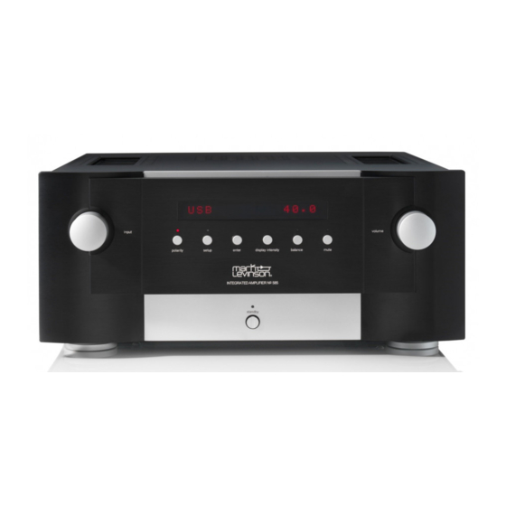
GETTING STARTED GETTING STARTED FRONT-PANEL OVERVIEW Front-Panel Volume Select Knob Receiver Display Knob Setup Button Standby Balance and LED Button Button and and LED Polarity Button Enter Display Mute Button and LED Button Intensity and LED Button Front-panel controls/indicators controlled via its rear-panel IR Input connector (see Rear- Panel Overview, page 7, for more information). - Page 7 GETTING STARTED Display Intensity button: Press this button to change the Standby button and LED: Press this button to put the N intensity of the N 585’s front-panel Display characters into and out of the Standby mode. The LED illuminates and its front-panel LEDs.
- Page 8 GETTING STARTED REAR-PANEL OVERVIEW Right Channel Left Channel Balanced Analog Balanced Analog Input Connector Input Connector Right Channel Left Channel Line Output Line Output Connector Connector Right Channel Left Channel Single-Ended Analog Single-Ended Analog Left Channel Right Channel Input Connectors Input Connectors Loudspeaker Loudspeaker...
- Page 9 GETTING STARTED Balanced analog input connectors: These connectors NOTE: For complete information about the rear- accept left-channel and right-channel balanced input panel connections, see the N 585 User Guide. at www. signals from source components with balanced (male XLR) marklevinson.com. output connectors.
- Page 10 GETTING STARTED Ethernet port: This port supports connection to a home network. For information on how to configure and use the Ethernet port, see the N 585 User Guide. IR input connector: This connector accepts IR (infrared) control signals from other equipment. RS-232 port: This RJ-11 connector provides serial control through a standard RS-232 connection.
-
Page 11: Remote Control Overview
GETTING STARTED REMOTE CONTROL OVERVIEW NOTE: For complete information about the remote control functions, see the N 585 User Guide. at www. marklevinson.com. Standby Button Standby button: Press this button to put the N 585 into and out of the Standby mode. Select buttons: Press these buttons to select the desired input. - Page 12 GETTING STARTED Polarity button: Pressing this button inverts the absolute polarity of the signal at the Speaker outputs and the Line outputs. The Polarity LED on the front panel illuminates when the signal's polarity is inverted. Display button: Press this button to change the intensity of the N 585’s front-panel display characters and its front- panel LEDs.
-
Page 13: Quick Setup And Listen
QUICK SETUP AND LISTEN QUICK SETUP AND LISTEN REMOTE CONTROL Using the Remote Control When using the remote control, aim it toward the N 585's Battery Installation front panel IR receiver. Make sure that no objects, such as Your N 585 remote control comes with two AAA alkaline furniture, block the remote’s view of the receiver. - Page 14 QUICK SETUP AND LISTEN INITIAL CONNECTIONS 5. Connect the supplied power cable to the N 585's AC NOTE: For complete information about making Mains connector and into an electrical outlet. Power on connections, see the N 585 User Guide. at www. the N 585 and all associated components.
- Page 15 QUICK SETUP AND LISTEN Digital Source Computer Component To Digital Output To USB Port Single-Ended Analog Source Component Balanced Analog Source Component Right Left Speaker Speaker 585 INTEGRATED AMPLIFIER / QUICK-START GUIDE...
-
Page 16: Troubleshooting
Standby button. Wait 10 to 15 minutes to let the unit cool down and press the Standby button again. If the error message does not clear call your Mark Levinson dealer or Mark Levinson customer service. WARNING: OVER CURRENT •... -
Page 17: Specifications
SPECIFICATIONS SPECIFICATIONS AMPLIFIER SECTION Output Power: 200W RMS per channel @ 8 Ω, 20Hz – 20kHz Damping Factor: >400 @ 20Hz, referred to 8 Ω Frequency Response: 20Hz – 20kHz, ±0.13dB; 2Hz – 250kHz, +0.2dB/–3dB Signal-to-Noise Ratio: >98dB (20Hz – 20kHz, unweighted); >103dB (20Hz – 20kHz, A-wtd), referred to full output –... - Page 18 Northridge, CA 91329 USA © 2014 HARMAN International Industries, Incorporated. All rights reserved. Mark Levinson is a registered trademark of HARMAN International Industries, Incorporated. Other company and product names may be trademarks of the respective companies with which they are associated.
Need help?
Do you have a question about the ?585 and is the answer not in the manual?
Questions and answers