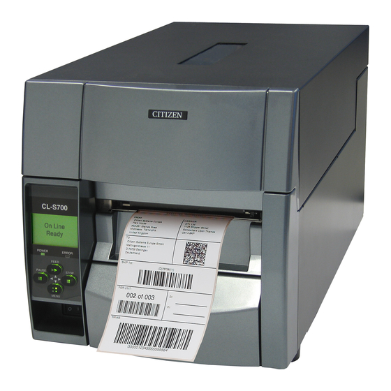
Citizen CL-S700 User Manual
Thermal transfer barcode & label printer
Hide thumbs
Also See for CL-S700:
- Programming manual (95 pages) ,
- User manual (71 pages) ,
- Technical manual (71 pages)
Table of Contents
Advertisement
Advertisement
Table of Contents

Related Manuals for Citizen CL-S700


Summary of Contents for Citizen CL-S700
- Page 1 Thermal Transfer Barcode & Label Printer CL-S700 SER'S ANUAL...
-
Page 2: Table Of Contents
CONTENTS Before Operation INTRODUCTION -------------------------------------------------------------------- 3 COMPLIANCE STATEMENT FOR EUROPEAN USERS ----------------------------- 4 FCC COMPLIANCE STATEMENT FOR AMERICAN USERS ----------------------- 4 EMI COMPLIANCE STATEMENT FOR CANADIAN USERS------------------------ 5 ETAT DE CONFORMITE EMI A L’USAGE DES UTILISATEURS CANADIENS ----- 5 IMPORTANT SAFETY INSTRUCTIONS --------------------------------------------- 6 NOTICE ------------------------------------------------------------------------------- 7 SAFETY INSTRUCTIONS ------------------------------------------------------------ 8 Chapter 1 Setup... -
Page 3: Introduction
INTRODUCTION Thank you for purchasing a Citizen CL-series label printer offering high performance printing at up to 10 inches per second on media up to 4.65 inches wide. ❚❚❚ ❚❚❚ Main Features <Easy Access - Easy Operation> The printer is designed for all day-to-day operations to be accessible from the front of the printer so there is no need to move items near to the printer for access for media loading. -
Page 4: Compliance Statement For European Users
COMPLIANCE STATEMENT FOR EUROPEAN USERS CE marking shows conformity to the following criteria and provisions: Low Voltage Directive (73/23/EEC)/EN60950-1 EMC Directive (89/336/EEC)/EN55022, EN55024, EN61000-3-2 & EN61000-3-3 This product has been tested under EN ISO 7779 and has an acoustic level output no higher than 55db(A). -
Page 5: Emi Compliance Statement For Canadian Users
EMI COMPLIANCE STATEMENT FOR CANADIAN USERS This Class A digital apparatus complies with Canadian ICES-003. This equipment generates and uses radio frequency energy and if not installed and used properly, that is, in strict accordance with the manufacturer's instructions, may cause interference to radio and television reception. -
Page 6: Important Safety Instructions
IMPORTANT SAFETY INSTRUCTIONS • Read all of these instructions and save them for later reference. • Follow all warnings and instructions marked on the product. • Unplug this product from the wall outlet before cleaning. Do not use liquid or aerosol cleaners. Use a damp cloth for cleaning. -
Page 7: Notice
• Please contact us if there are any mistakes or ambiguities within this manual. • If there are missing or incorrectly collated pages in this manual, contact us to obtain a new manual. CITIZEN is a registered trademark of CITIZEN HOLDINGS CO., Japan. CITIZEN es una marca registrada de CITIZEN HOLDINGS CO., Japón. -
Page 8: Safety Instructions
SAFETY INSTRUCTIONS which must be strictly observed ! • To prevent personal injury or property damage, the following shall be strictly observed. • The degree of possible injury and damage due to incorrect use or improperly following instructions is described below. Indicates a situation which, if not observed and handled Warning properly, could result in death or serious injury. -
Page 9: General Precautions
General Precautions Caution • Prior to operation, read the safety instructions carefully and observe them. • Do not drop or put foreign matter such as clips and pins into the printer. This may cause problems. • Be careful when moving or carrying the printer. Dropping the printer may cause injury or property damage. -
Page 10: Chapter 1 Setup
Setup Confirmation of Carton Contents Removing the Packing Material The printer is shipped with adhesive tape in place to hold the top cover closed. Simply remove the two pieces of tape on either side of the top cover. Then simply open the cover by lifting up and tipping it backwards. There is another strip of adhesive tape that must be removed which holds the mechanism closed for shipping. -
Page 11: Part Names And Functions
Setup Caution • Be careful when moving or carrying the printer and when taking the printer out of the carton. The printer may cause injury or property damage if dropped. Be sure to grip the printer housing firmly when taking it out of the carton. Do not grip the printer by the foam packing material which may break, causing the printer to drop. - Page 12 Setup Part Names and Functions 1 Ribbon holder It is used to attach the ribbon and paper core. 2 Media holder guide This guide is moved horizontally to match the media size. The guide can be sliding it from the holder bar. 3 Media holder bar The media is supported by the media holder bar when installed in the printer.
- Page 13 Setup Part Names and Functions Media Thickness Adjustment 1 Media thickness adjustment screw (p.49) It is adjusted to match the thickness of the media. 2 Media width adjustment indicator 3 Media width adjustment knob Media Width Adjustment (p.50) It is adjusted to match the width of the media. 4 Media thickness adjustment indicator 5 Head open lever The head unit can be raised to install media by pushing this lever.
- Page 14 Setup Part Names and Functions 1 Thermal printhead This is the printhead. Avoid touching this with your fingertips and leaving grease or dirt on the printhead surface. 2 Sensor arm The media can be installed by raising this arm. The media can be held in place by lowering this arm. 3 Adjustable (rear) sensor Sensor Adjustments and Calibration (p.46)
-
Page 15: Operation Panel
Setup Part Names and Functions Operation Panel POWER ERROR FEED PAUSE STOP MENU 1 LCD display LED Functions (p.21) This displays the operational status of the printer. 2 POWER LED This is lit when the printer power is on. (green) 3 ERROR LED This is lit or flashes when the printer is in an alarm or error status. - Page 16 Setup Part Names and Functions Rear View 1 Parallel interface (Centronics parallel or IEEE1284) Parallel Interface (p.63) This receives parallel transmission of data from a host computer. 2 Serial interface (RS232C) Serial Interface (p.61) This receives serial transmission of data from a host computer. 3 USB interface USB Interface (p.66) This receives USB transmission of data from a host computer.
-
Page 17: Connection To Power
Setup Connection to Power 1. The power switch is located on the front of the printer recessed below the control panel. Check that the power switch is turned OFF. 2. Insert the power cord in to the inlet on the printer. 3. -
Page 18: Connection To A Computer
Setup Connection to a Computer This product has three interfaces that can be used to receive printing data: a serial port (RS232C), parallel port (IEEE1284, Non-L. P. S.), and a USB port (USB1.1). An optional internal network interface can be added by your dealer. -
Page 19: Chapter 2 Printer Operation
Printer Operation Printer Operation Power ON/OFF Turning on the power 1. The power switch is conveniently located at the front of the printer for easy access during normal operation. It is in the recess underneath the control panel so it cannot be accidentally operated by mistake. -
Page 20: Normal Operating Mode
Printer Operation Normal Operating Mode When the power is turned on, the printer enters normal operating mode. Menu Setup Mode (p.31) The control keys activate the following functions. On Line Ready POWER ERROR FEED PAUSE STOP MENU 1 PAUSE key: Temporarily pauses printing •... -
Page 21: Led Functions
Printer Operation Normal Operating Mode LED Functions 1 POWER LED It lights up when printer power is turned POWER ERROR on. (green) FEED PAUSE STOP 2 ERROR LED This is lit or flashes when the printer is in error status. (orange) MENU Table of Alarm and Error Indications In addition to normal operating mode, when an abnormal condition is detected... -
Page 22: Setting The Media
Printer Operation Setting the Media Media Sizes The position of label and tag media is sensed by either a transparent sensor or a reflective sensor. Transparent sensor: Detects the gaps between label media and notches of tag media Reflective sensor: Detects the black mark Size of media Label media... - Page 23 Printer Operation Setting the Media When Using Front Sensors Minimum value mm (in) Maximum value mm (in) Label width 7 .62 (0.3) 1 18.00 (4.65) Liner width 25.40 (1.0) 1 18.00 (4.65) Left end of label 2.54 (0.10) Gap between labels 2.54 (0.10) 812.80...
- Page 24 Printer Operation Setting the Media Installing the Media 1. Push the large blue head-open lever to release the head unit, and then lift the sensor arm by hand as shown the right side drawing below. Head unit Sensor arm open lever Sensor arm Large blue-head open lever 2.
- Page 25 Printer Operation Setting the Media 4. Set the media roll and media holder in to the printer as shown above. It is advisable to pull a length of media forwards and through the mechanism ready for later positioning. 5. Move the media roll so it is touching the left side of the housing. Then slide the black movable media guide so it is touching the media on the right side.
-
Page 26: Setting The Ribbon
Printer Operation Setting the Ribbon The following kinds and sizes of ribbons can be used. Types ............Inside wound and outside wound ribbon Max. ribbon width ....... 1 14.0 mm (4.50 inch) Min. ribbon width ........ 25.4 mm (1.00 inch) Max. - Page 27 Printer Operation Setting the Ribbon 3. Push the large blue head-open lever to release the head unit. Pull out the ribbon from the bottom of the head unit to the ribbon winding side. 4. Using tape etc., fix the ribbon that you have pulled out on the ribbon holder on which the paper core has been set and wind it on the ribbon holder.
- Page 28 Printer Operation Setting the Ribbon Adjusting the Ribbon (p.51) 6. Lower the head unit back down to the closed position. Push the head close knob firmly to close and lock the mechanism. The mechanism is only locked correctly when you head a “click”. If the ribbon is wrinkled, push the FEED key until the wrinkles disappear.
-
Page 29: Mode Settings
Printer Operation Mode Settings Operation Panel (P.15) Turning on the power while pressing keys in the following combinations starts various functions. Mode Key operation HEX dump mode Turning power on while pushing the STOP key. Self print mode Turning power on while pushing the FEED key. Menu list print mode and Turning power on while pushing the MENU key. - Page 30 Printer Operation Mode Settings Self Print Mode Performing a self test print is an easy way to check on the state of printer settings and printing quality. Install the media as explained in “Installing the Media” and then operate the printer as follows. Setting the Media (P.22) Case of label media Turn on printer power while...
- Page 31 Printer Operation Mode Settings Menu Setup Mode If the MENU key is pressed while the printer is in the On Line Ready state, the printer enters menu setup mode. In this mode, the printer's configuration can be changed using the operation panel. During menu setting mode, the LCD indicates the current menu settings and the key function.
- Page 32 Printer Operation Mode Settings Example of changing a menu This is an explanation of the method of changing the set value of print darkness from “12” to “14” in a case where the main menu is “Page Setup” and the sub menu is “Print Darkness”. 1.
- Page 33 Printer Operation Mode Settings 2. Entering Sub menu. Press the 3 key. The currently set item, “Print Speed”, is displayed. Page Setup Print Speed Exit Enter The following are the functions of each key. 5 key: displays the previous sub menu ∞...
- Page 34 Printer Operation Mode Settings 6. Save the changed value permanently. Unless you perform the following save operation, the new setting value will be lost when you turn off the printer. To Save Changes 1 Press the 2 key twice to display the Save Settings message “Save Settings No-Discard”.
- Page 35 USB VCOM Protocol : Auto <Example of Datamax emulation selected> Note: Citizen continually enhances its printers with new options and settings based on our customer's requests. Extra or changed menu items may appear on the above print out in some cases.
- Page 36 Printer Operation Mode Settings Global Configuration Sets The printer can store three sets of configuration settings that can be recalled quickly and easily. Each “Config Set” (1, 2 or 3) can contain completely different configuration settings for all menu parameters. For example, “Config Set 1” could be config- ured for 5 ips print speed, thermal transfer labels, print darkness 18.
-
Page 37: Menu Setting
Printer Operation Mode Settings [Datamax Emulation] Menu Setting Table Page Setup Menu - allows you to change settings related to the media or print quality. System Setup Menu - allows you to change settings for the printer hardware and basic control systems. After Print Menu - changes how the printer reacts after the label has been printed. - Page 38 Printer Operation Mode Settings [Datamax Emulation] Top Menu Sub Menu Default Menu Remarks Metric/Inch Inch Inch Sets the units. [Metric/Inch Sel] Max Media Length 10.00 inch 1.00 to 50.00 inch Sets the maximum media length. [Max Media Len] 254.0 mm 25.4 to 1270.0 mm Settings Lock Prevents a command changing the set value.
- Page 39 Printer Operation Mode Settings [Datamax Emulation] Top Menu Sub Menu Default Menu Remarks Menu Key Action Enters Menu Enters Menu Sets the menu key action. Repeat Last Set Enters Menu: Repeat Last One Enters the menu setup mode. Repeat Last Set: Repeats the number of copies.
- Page 40 Printer Operation Mode Settings [Datamax Emulation] Top Menu Sub Menu Default Menu Remarks Factory Default Initializes the set values of the configuration set to the state when the unit was shipped from the factory. Hex Dump Sets the hex dump mode. Serial Monitor –...
- Page 41 Printer Operation Mode Settings [Zebra Emulation] 7 Zebra Emulation Top Menu Sub Menu Default Menu Remarks Page Setup Print Speed 7 IPS 2 to 10 IPS Printing speed setting. Print Darkness 00 to 30 Adjusting print darkness. Darkness Adjust -10 to 10 Fine adjustment of darkness commands.
- Page 42 Printer Operation Mode Settings [Zebra Emulation] Top Menu Sub Menu Default Menu Remarks Emulation Select Selects DataMax/Zebra compatibility [Emulation Sel] DM4: DataMax 400 DMI: DataMax IClass ZPI2 DPP: DataMax Prodigy Plus ZPI2: Zebra 2844Z Emulation Auto Setting emulation (Datamax/Zebra) auto Detect detection.
- Page 43 Printer Operation Mode Settings [Zebra Emulation] Top Menu Sub Menu Default Menu Remarks RS-232C Parity None None Setting the communication parity for the serial interface. Even RS-232C Length 8 bits 8 bits Setting the character length for the serial 7 bits interface.
-
Page 44: Quick Setup Of The Print Method
Printer Operation Quick Setup of the Print Method Menu Setup Mode (p.31) The print method (thermal transfer method/direct thermal method) can be set using operation panel in addition to menu setting mode. Caution Be sure to always shut off the operation of print before changing a setting. -
Page 45: Emulation Auto-Detection
Printer Operation Emulation Auto-Detection Menu Setup Mode Ordinarily emulation switching is conducted in the Menu Setup mode. (p.29, p38, p42) However, switching can also be conducted using the Emulation Auto- Detection function outlined below. The following message is displayed on the LCD when the Zebra emulation (ZPI2) command is detected during Datamax emulation. -
Page 46: Chapter 3 Printer Adjustments
Printer Adjustments Printer Adjustments Sensor Adjustments and Calibration The sensing level of both the transparent (see thru) and reflective sensors is adjusted separately and independently. Firstly, the sensor type must be selected using the Sensor Method Selection shown below. Then the adjustment and calibration of the sensor can be made. - Page 47 Printer Adjustments Sensor Adjustments and Calibration Adjusting the Transparent sensor Installing the Media (p.24) 1. The transparent sensor is selected. Quick Sensor Selection 2. Install only the liner media (label backing paper) with the label Method media removed so that it will pass between the platen roller and (Transparent ↔...
- Page 48 Printer Adjustments Sensor Adjustments and Calibration Adjusting the Reflective sensor Quick Sensor Selection 1. The reflective sensor is selected. Method 2. With the reflective sensor selected, install the label media so (Transparent ↔ Reflective) that it is between the platen roller and the media sensor. (p.46) Be careful that black mark and media gap do not pass the media sensor.
-
Page 49: Media Thickness Adjustment
Printer Adjustments Media Thickness Adjustment Installing the Media (p.24) The printer is already factory-set to the requirements of proper print quality while using the recommended labels. If the print quality is inferior because of the different type of media, adjust the printhead position in the following manner: When using standard labels, or thermal media Self Print Mode (p.30) -
Page 50: Media Width Adjustment
Printer Adjustments Media Width Adjustment Installing the Media (p.24) The printer is already factory-set to the value of media width: 1 12 mm (4.4 in). When you use narrow media, adjust the printhead pressure in the following: 1. Looking in at the check window on the upper frame, align the mark (the left end of white plastic) with the width of media by turning the media width adjustment knob. -
Page 51: Adjusting The Ribbon
Printer Adjustments Adjusting the Ribbon Setting the Ribbon (p.26) Ribbon tension in this printer is already adjusted for the recommended ink ribbon and media and is very tolerant to different types of media. However, it may slip due to imperfect combinations of ribbon and media and it is possible that you will see a “Ribbon End”... - Page 52 Printer Adjustments Adjusting the Ribbon 2. Easy-to-slip ribbon and media If a message ‘Ribbon Out’ is shown, set the mark on the feeding section to LOW by turning the adjust-screw. Winding section TENSION Feeding section STANDARD TENSION STANDARD SUPER LOW 3.
-
Page 53: Operating Procedure
Printer Adjustments Moving the Adjustable Sensor Operating procedure Menu Setting Table (p.37) Measure your required detection position beforehand, using the scale on the upper guide rail. Move the adjustable sensor to the Ensure the adjustable sensor is selected. required detection position by tuning the adjustable knob; it is useful to align the yellow mark on the top of the adjustable sensor with the scale showing the required detection position. -
Page 54: Cleaning
Printer Adjustments Cleaning Wipe off any foreign matter such as media dust, dirt and adhesive substances built up around the printhead and platen with the head cleaning pen (head cleaner) provided, and use a soft cloth soaked in ethyl alcohol for the platen etc. -
Page 55: Chapter 4 Troubleshooting
Troubleshooting Troubleshooting This chapter explains corrective actions taken when the printer malfunctions or when an error message is displayed. Items to check when a malfunction occurs When the printer malfunctions during operation, take corrective action with reference to the following table. If the corrective action does not solve the problem, consult with the service personnel at the dealer where you purchased the printer. - Page 56 Troubleshooting Indication Check Corrective action The printer is not 4) Is the thermal printhead 4) If it is dirty, remove the dirt with the printing neatly. dirty? attached head cleaner. Is a label stuck to the head. If a label is stuck to the head, remove Note: Do not use a metal object to remove a label stuck to the inside of the printer.
-
Page 57: Appendixes
Appendixes Appendixes Specifications Item Description Printing Printing method Thermal transfer/Direct thermal Resolution Main scanning line density: 203 dots/inch (8 dots/mm) Sub- scanning line density: 203 dots/inch (8 dots/mm) Head 864 dots (printable dots: 832 dots) Max. print width 104 mm 4.1 inch Max. - Page 58 Appendixes Specifications Item Description Bar code One-dimension • Code 3 of 9 • UPC-A • UPC-E • EAN-13 (JAN-13) (for Datamax emulation) • EAN-8 (JAN-8) • Interleaved 2 of 5 • Code 128 • HIBC (Modulus 43-used code 3 of 9) • Codabar (NW-7) •...
- Page 59 Appendixes Specifications Item Description Media detection Transparent sensor Detects media gap between labels, notches on tags, and media out sensors Reflective sensor Detects reflective mark on back of media and media out Label peeling sensor Communication Parallel IEEE1284 (compatible, Nibble, ECP mode) interfaces Serial 2400 4800 9600 19200 38400 57600 1 15200bps...
- Page 60 Appendixes Item Description Weight Approx. 13.3 kg (29.3 lb.) Accessories Test label media, Test ribbon, CD-ROM (User’s Manual), Quick start guide, Head cleaner, Power cord, Media holder bar and Media holder guide, Ribbon holder, Paper core Option Auto-cutter unit, Peeler unit and Ethernet interface board *1, *2: Options can be separately purchased.
-
Page 61: Interfaces
Appendixes Interfaces This printer is connected to a computer and prints according to commands sent from the computer. There are three types of computer interfaces, and these are connected to devices suited to each type of interface. The printer can also be connected to a computer by the optional Ethernet. - Page 62 Appendixes Interfaces XON/XOFF Protocol Requirements to output X-ON code • Communication is possible when the power is on. • When the receive buffer has less than 128 bytes available, XOFF code is output, then the receive buffer has at least at least 1024 bytes available. Requirements to output the X-OFF code •...
-
Page 63: Parallel Interface
Appendixes Interfaces Parallel Interface Specifications Transmission mode 8-bit parallel data Receive buffer size 16K bytes Transmission modes Compatible mode It is an asynchronous forward direction of the byte width (from host to printer) channel, and the interface line of the data is operated in accordance with signal line definitions of Centronics. - Page 64 Appendixes Interfaces Parallel port status signals when an error occurs The status of a signal line will not be changed in bi-directional mode such as nibble or ECP mode. Error Change in the status of a signal line in compatible mode Paper end Busy PError : L...
- Page 65 Appendixes Interfaces [While receiving INIT signal] Min. 10 to 15µsec *Init BUSY *Ack *Fault SELECT Note: If the *Init signal does not have width of 10 to 15 µ sec or more, it cannot act as an Init signal. If it is lower, the *Init signal is ignored. BUSY starts up when the *Init signal is perceived.
-
Page 66: Usb Interface
Appendixes Interfaces USB Interface Specifications Standards Complies with Universal Serial Bus Specification Transmission speed Compatible with 12Mbps (full speed) transmission Receive buffer 16K bytes Connector DUSB DUSB-BRA42-T1 1(DDK) Signal line and pin arrangement Pin No. Signal code Signal Function VBUS USB power USB power (+5V) Signal line +... -
Page 67: Replacing The Interface Board
Appendixes Replacing the Interface Board Caution Always turn off the power to the printer before replacing the interface board. Do not pull it out with unnecessary force. This will cause an accident. Replacement Method 1. Remove the screws (2) that anchor the bracket of the interface board then pull the interface board towards you. - Page 68 Appendixes Replacing the Interface Board 3. Insert the interface board into the printer so that the connecting cable does not catch on the printer, then use the screws (2) that you removed to anchor the bracket. Interface Board Rear Side Screw...
- Page 70 363 Van Ness Way, Suite 404 Torrance, CA 90501. USA Tel: (310) 781-1460 Fax:(310) 781-9152 http://www.citizen-systems.com Mettinger Strasse 11 Park House, 643-651 Staines Road D-73728, Esslingen Feltham, Middlesex, TW14 8PA Germany United Kingdom Tel: +49 (0) 711 3906 420 Tel: +44 (0) 20 8893 1900...
Need help?
Do you have a question about the CL-S700 and is the answer not in the manual?
Questions and answers