Table of Contents
Advertisement
Advertisement
Table of Contents

Related Manuals for Citizen CL-S6621


Summary of Contents for Citizen CL-S6621
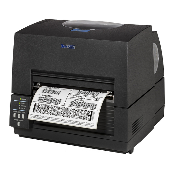
- Page 1 Thermal Transfer Barcode & Label Printer CL-S6621 SER'S ANUAL...
-
Page 2: Table Of Contents
CONTENTS Before Operation INTRODUCTION..........................3 COMPLIANCE.STATEMENT.FOR.EUROPEAN.USERS............4 GS.MARK.STATEMENT........................4 FCC.COMPLIANCE.STATEMENT.FOR.AMERICAN.USERS............ 4 EMI.COMPLIANCE.STATEMENT.FOR.CANADIAN.USERS............ 5 ETAT.DE.CONFORMITE.EMI.A.L’USAGE.DES.UTILISATEURS.CANADIENS..... 5 IMPORTANT.SAFETY.INSTRUCTIONS..................6 NOTICE..............................7 SAFETY.INSTRUCTIONS......................... 8 Chapter 1 Setup Confirmation.of.Carton.Contents...................10 Part.Names.and.Functions......................11 Connection.to.Power........................17 Driver.Installation.........................17 Connection.to.a.Computer......................18 Chapter 2 Printer Operation Power.ON/OFF..........................19 Normal.Operating.Mode. -
Page 3: Introduction
INTRODUCTION Thank.you.for.purchasing.a.Citizen.CL-series.label.printer.offering.high.performance.thermal.transfer. printing.on.media.up.to.6.inches.wide. ■■■ ■■■ Main Features <High-speed, high-quality printing> This.printer.can.be.used.for.high-speed.high-quality.printing.thanks.to.its.direct.thermal.method. and.thermal.transfer.method.that.use.a.line.thermal.printhead.together.with.its.32.bit.RISC.CPU. and.its.‘history.control.IC’ . <Easy operation> . • It.is.easy.to.change.the.printer’s.settings.on.the.operation.panel,.thanks.to.its.unique.and. simple.VuePrint.menu.system. . • Its.high-lift.printhead.and.mechanism.means.that.media.and.ribbon.can.be.loaded.with. ease.and.it.is.constructed.for.easy.thermal.printhead.cleaning,.etc. . • Media.width.adjustment,.media.thickness.adjustment,.and.media.sensor.adjustment.can. all.be.made.easily.by.the.user.using.the.colour-coded.operator.controls. <Dual Programming Language> This.printer.contains.both.the.Datamax®.and.Zebra®.emulations.and.will.automatically. detect.the.language.using.the.Cross-Emulation .feature. <Interface> An.industry.standard.RS232.serial.port.and.USB2.0.port.are.standard.equipment,.for.quick. data.transfer.and.printing. <Optional interface> Additional.connectivity.is.available.with.an.optional.internally-housed.IEEE1284.parallel.port,. -
Page 4: Compliance.statement.for.european.users
COMPLIANCE STATEMENT FOR EUROPEAN USERS CE marking shows conformity to the following criteria and provisions: Low Voltage Directive (2006/95/EC, formerly 73/23/EEC)/EN60950-1 EMC Directive (2004/108/EC, formerly 89/336/EEC)/EN55022, EN55024, EN61000-3-2 & EN61000-3-3 GS MARK STATEMENT This product has been tested under EN ISO 7779 and has an acoustic level output no higher than 70dB(A). -
Page 5: Emi.compliance.statement.for.canadian.users
EMI COMPLIANCE STATEMENT FOR CANADIAN USERS This Class A digital apparatus complies with Canadian ICES-003. This. equipment. generates. and. uses. radio. frequency. energy. and. if. not. installed. and. used. properly,.that.is,.in.strict.accordance.with.the.manufacturer’s.instructions,.may.cause.interference. to.radio.and.television.reception..This.digital.apparatus.does.not.exceed.the.Class.A.limits.for. radio.noise.emissions.from.digital.apparatus.set.out.in.the.Radio.Interference.Regulations.of.the. Canadian.Department.of.Communications..This.equipment.is.designed.to.provide.reasonable. protection.against.such.interference.in.a.residential.installation..However,.there.is.no.guarantee. that. interference. will. not. occur. in. a. particular. installation.. If. this. equipment. does. cause. interference.to.radio.or.television.reception,.which.can.be.determined.by.turning.the.equipment. -
Page 6: Important.safety.instructions
IMPORTANT SAFETY INSTRUCTIONS •. Read.all.of.these.instructions.and.save.them.for.later.reference. •. Follow.all.warnings.and.instructions.marked.on.the.product. •. Unplug.this.product.from.the.wall.outlet.before.cleaning..Do.not.use.liquid.or.aerosol.cleaners..Use.a. damp.cloth.for.cleaning. •. Do.not.use.this.product.near.water. •. Do.not.place.this.product.on.an.unstable.cart,.stand.or.table..The.product.may.fall,.causing.serious. damage.to.the.product. •. Slots.and.openings.on.the.cabinet.and.the.back.or.bottom.are.provided.for.ventilation. . To.ensure.reliable.operation.of.the.product.and.to.protect.it.from.overheating,.do.not.block.or.cover.these. openings..The.openings.should.never.be.blocked.by.placing.the.product.on.a.bed,.sofa,.rug.or.other. similar.surface..This.product.should.never.be.placed.near.or.over.a.radiator.or.heat.register..This.product. should.not.be.placed.in.a.built-in.installation.unless.proper.ventilation.is.provided. •. This.product.should.be.operated.from.the.type.of.power.source.indicated.on.the.marking.label. . If.you.are.not.sure.of.the.type.of.power.available,.consult.your.dealer.or.local.power.company. •. This.product.is.equipped.with.a.three-pronged.plug,.a.plug.having.a.third.(grounding).pin..This.plug.will. only.fit.into.a.grounding-type.power.outlet..This.is.a.safety.feature..If.you.are.unable.to.insert.the.plug.into. the.outlet,.contact.your.electrician.to.replace.your.obsolete.outlet..Do.not.defeat.the.safety.purpose.of.the. grounding-type.plug. •. Do.not.allow.anything.to.rest.on.the.power.cord..Do.not.locate.this.product.where.the.cord.will.be.walked. •. If.an.extension.cord.is.used.with.this.product,.make.sure.that.the.total.of.the.ampere.ratings.on.the. products.plugged.into.the.extension.cord.do.not.exceed.the.extension.cord.ampere.rating..Also,.make. sure.that.the.total.of.all.products.plugged.into.the.wall.outlet.does.not.exceed.15.amperes.for.120V.outlet. and.7.5.amperes.for.220V-240V.outlet. •. Never.push.objects.of.any.kind.into.this.product.through.cabinet.slots.as.they.may.touch.dangerous. voltage.points.or.short.out.parts.that.could.result.in.a.risk.of.fire.or.electric.shock..Never.spill.liquid.of.any. -
Page 7: Notice
•. We. are. not. liable. for. any. damage. caused. by. user's. erroneous. use. of. the. printer. and. inadequate. environment. •. Data.residing.in.the.printer.is.temporary..Therefore,.all.data.will.be.lost.if.power.is.lost..We.are.not.liable.for. any.damage.or.loss.of.profits.caused.by.data.loss.due.to.failures,.repairs,.inspections,.etc. •. Please.contact.us.if.there.are.any.mistakes.or.ambiguities.within.this.manual. •. If.there.are.missing.or.incorrectly.collated.pages.in.this.manual,.contact.us.to.obtain.a.new.manual. CITIZEN is a registered trademark of CITIZEN HOLDINGS CO., Japan. CITIZEN es una marca registrada de CITIZEN HOLDINGS CO., Japón. Copyright © 2012 by CITIZEN SYSTEMS JAPAN CO., LTD. -
Page 8: Safety.instructions
SAFETY INSTRUCTIONS which must be strictly observed ! • To prevent personal injury or property damage, the following shall be strictly observed. • The degree of possible injury and damage due to incorrect use or improperly following instructions is described below. Indicates a situation which, if not observed and handled Warning properly, could result in death or serious injury. -
Page 9: General Precautions
General Precautions Caution •. Prior.to.operation,.read.the.safety.instructions.carefully.and.observe.them. •. Do.not.drop.or.put.foreign.matter.such.as.clips.and.pins.into.the.printer..This.may.cause.problems. •. Be.careful.when.moving.or.carrying.the.printer..Dropping.the.printer.may.cause.injury.or.property. damage. •. Make.sure.if.you.open.the.top.cover,.it.is.opened.all.the.way..If.only.partially.open,.the.cover.could. slam.shut,.possibly.causing.injury. •. When.the.cover.is.open,.be.careful.of.the.corners.of.the.cover..They.could.cause.injury. •. Do.not.open.the.printer.during.printing. •. When.cleaning.the.surface.of.the.printer.case,.do.not.use.the.cloth.that.is.soaked.in.thinner,. trichloroethylene,.benzine,.ketone.or.similar.chemicals. •. Do.not.use.the.printer.where.there.is.a.lot.of.oil,.iron.particles,.or.dust. •. Do.not.spill.liquids.or.spray.insecticide.on.the.printer. •. Do.not.jolt.or.impact.to.the.printer.by.stepping.on,.dropping.or.hitting.the.printer. •. Operate.the.control.panel.properly..A.careless,.rough.handling.may.cause.problems.or.malfunction.. Do.not.use.such.sharp-edged.tool.as.a.ballpoint.pen.for.operation. •. Be.careful.of.the.edges.of.the.plates.so.injury.or.property.damage.is.possible. •. If.a.problem.occurs.during.printing,.stop.the.printer.immediately.and.unplug.the.power.cord.from. the.outlet. •. When.printer.trouble.occurs,.do.not.try.to.dissemble.it..Instead,.consult.our.service.personnel. Precautions When Installing the Printer Caution •. -
Page 10: Chapter 1 Setup
Chapter 1 Setup Chapter 1 Setup Confirmation of Carton Contents Removing the Packing Material The.printer.is.shipped.with.adhesive.tape.in.place.to.hold.the.top.cover. closed...Simply.remove.the.two.pieces.of.tape.on.either.side.of.the.top. cover..Then.simply.open.the.cover.by.lifting.up.and.tipping.it.backwards. There.is.another.strip.of.adhesive.tape.that.must.be.removed.which.holds. the.mechanism.closed.for.shipping...Remove.the..tape.and.attached. paper.by.carefully.peeling.from.the.plastic.case. Retain.the.tape.should.you.need.to.transport.the.printer.again.. Check that the following accessories are included with the printer in the carton. Ribbon Holder Sample Ribbon Paper Core Head cleaner Media holder guide Media holder bar... -
Page 11: Part.names.and.functions
Chapter 1 Setup Caution . • Be.careful.when.moving.or.carrying.the.printer.and.when.taking.the. printer.out.of.the.carton..The.printer.may.cause.injury.or.property. damage.if.dropped..Be.sure.to.grip.the.printer.housing.firmly.when. taking.it.out.of.the.carton..Do.not.grip.the.printer.by.the.foam. packing.material.which.may.break,.causing.the.printer.to.drop. . • When.opening.the.cover,.open.it.all.the.way..If.only.part.way. open,.the.cover.could.slam.shut,.possibly.causing.injury. . • Be.careful.of.the.edge.of.the.cover.when.the.cover.is.opened..It. may.cause.injury.or.property.damage. . • Be.careful.of.the.edges.of.the.metal.plates.so.injury.or.property. damage.is.possible. Part Names and Functions Front View 1 Top cover Is.opened.vertically.to.set.media.or.ribbon. 2 Operation panel Operation Panel (p.15) This.is.used.to.make.changes.and.adjustments.to.the.printer.and.its. configuration. -
Page 12: Inside The Printer
Chapter 1 Setup Part Names and Functions Inside the printer 1 Ribbon drive unit 2 Head close knob Push.the.head.close.knob.to.lock.the.mechanism.closed..If.you.push. on.another.part.of.the.mechanism,.the.printer.may.not.lock.closed. correctly. 3 Ribbon holder It.is.used.to.attach.the.ribbon.and.paper.core. 4 Front cover It.is.removed.to.install.optional.units.such.as.the.peeler.or.cutter. - Page 13 Chapter 1 Setup Part Names and Functions 1 Front (winding side) ribbon tension adjustment knob Ribbon Tension Adjustment (p.52) This.is.adjusted.according.to.the.width.of.the.ribbon.that.is.used..It.is. also.used.when.the.ribbon.is.wrinkled.or.slips. 2 Front (winding side) ribbon left-right balance adjustment Ribbon Balance Adjustment (p.53) knob It.is.used.to.perform.an.adjustment.when.the.ribbon.is.wrinkled.. Normally.set.it.to.the.center.position. 3 Media width adjustment dial Media Width Adjustment (p.51) It.is.adjusted.to.match.the.width.of.the.media.
- Page 14 Chapter 1 Setup Part Names and Functions 1 Thermal printhead This.is.the.printhead..Avoid.touching.this.with.your.fingertips.and. leaving.grease.or.dirt.on.the.printhead.surface. 2 Sensor arm The.media.can.be.installed.by.raising.this.arm.. The.media.can.be.held.in.place.by.lowering.this.arm. 3 Upper sensor ( 3 -1) and bottom sensor ( 3 -2) Setting sensor positions (p.24) Used.as.a.transparent.sensor.or.a.reflective.sensor..Settings.for.sensor. Sensor Adjustments (p.47) position.and.sensor.adjustment.should.be.performed.in.accordance. with.the.type.of.sensor.used. 4 Media guides (Left fixed media guide ( 4 -1) and right Installing the Media (p.25) movable media guide ( 4 -2)) The.end.of.the.media.is.matched.to.the.left.fixed.media.guide,.then.the.
-
Page 15: Operation Panel
Chapter 1 Setup Part Names and Functions Operation Panel 1 POWER LED LED Functions (p.21) This.is.lit.when.the.printer.power.is.on..(green) 2 PRINT LED This.is.lit.when.the.printer.is.able.to.print..(green) 3 CONDITION LED This.is.on.when.selecting.settings..(orange) 4 ERROR LED This.is.lit.or.flashes.when.the.printer.is.in.an.alarm.or.error.status..(red) 5 PAUSE key Normal Operating Mode (p.20) This.temporarily.stops.printing. 6 FEED key This.key.feeds.the.media.to.the.top.of.the.next.label.or.form. 7 STOP key This.stops.printing.or.cancels.the.alarm. -
Page 16: Rear View
Chapter 1 Setup Part Names and Functions Rear View 1 Serial interface (RS232C) Serial Interface (p.62) This.receives.serial.transmission.of.data.from.a.host.computer. 2 Option interface Additional.option.interface.boards.can.be.mounted..Contact.your. retailer.if.you.want.to.use.the.option.interface. 3 USB interface USB Interface (p.64) This.receives.USB.transmission.of.data.from.a.host.computer. 4 Power switch Power ON/OFF (p.19) The.is.the.power.switch.for.the.printer. 5 Power cord inlet Connection to Power (p.17) The.connector.of.the.enclosed.power.cord.is.connected.here. -
Page 17: Connection.to.power
Chapter 1 Setup Connection to Power Caution Do.not.use.any.voltage.other.than.that.displayed..Doing.so.may.lead.to. damage.or.malfunction. 1. Check that the power switch to the printer is turned OFF. 2. Connect the connector of the power cord to the power cord inlet on the printer. 3. Insert the plug of the power cord in the AC outlet. Power Switch AC Outlet Power Cord Inlet Caution Use.an.AC.outlet.that.accepts.a.three-pronged.plug..Otherwise,.static. electricity.may.be.generated.and.there.will.be.danger.of.electric.shock. Driver Installation The.computer.may.automatically.detect.the.presence.of.the.new.printer. when.it.is.first.started,.depending.on.the.computer.type,.interface.and. operating.system...Follow.any.on-screen.instruction.and.also.instructions. supplied.with.any.additional.CD-ROM.included.with.your.printer. Your.supplier.will.assist.you.with.the.correct.drivers.and.software.which. are.compatible.with.your.particular.computer.system. -
Page 18: Connection.to.a.computer
Chapter 1 Setup Connection to a Computer This.product.has.two.interfaces.that.can.be.used.to.receive.printing. data:.a.serial.port.(RS232C).and.a.USB.port.(USB2.0)..An.optional.internal. Ethernet,.an.IEEE1284.Parallel.or.Wireless.LAN.port.can.be.added.by.your. dealer. With.the.exception.of.a.wireless.LAN.connection,.an.interface.cable.is. necessary.to.connect.the.printer.to.a.computer. To.connect.the.cable,.proceed.as.follows: 1. Turn OFF both power switches of the printer and the computer. 2. Connect one end of the interface cable to the interface connector on the back of the printer and secure it with locks or locking screws, where available. 3. Connect the other end of the interface cable to the interface connector on the computer and secure it with locks or locking screws, where available. Serial Interface (p.62) USB Interface (p.64) Serial Interface Cable USB Interface Cable Note:. If.an.optional.Ethernet,.an.IEEE1284.Parallel.or.Wireless.LAN.port.is. used,.contact.your.Citizen.Systems.dealer. -
Page 19: Chapter 2 Printer Operation
Chapter 2 Printer Operation Chapter 2 Printer Operation Power ON/OFF Turning on the power 1. Turn on the power switch on the back of the printer. 2. The POWER and PRINT LED are lit. Operation Panel Power Switch Turning off the power 1. Turn off the power switch on the back of the printer. 2. The POWER and PRINT LED go off. Power Switch... -
Page 20: Normal.operating.mode
Chapter 2 Printer Operation Normal Operating Mode Menu Setup Mode (p.33) When.the.power.is.turned.on,.the.printer.enters.normal.operating.mode.. The.control.keys.activate.the.following.functions. 1 PAUSE key: Temporarily pauses printing . • When.this.key.is.pushed.once,.the.PRINT.LED.turns.off.and.the. printer.temporarily.pauses. . • When.it.is.pushed.during.printing,.the.printer.pauses.after.the.label. currently.being.printed.is.issued..Pressing.the.key.a.second.time. restarts.printing.and.the.remaining.number.of.designated.labels.are. printed. 2 FEED key: Feeds media . • Pressing.this.key.feeds.media.to.the.print.start.position... The.distance.it.is.fed.is.determined.by.automatically.detecting. the.front.end.of.the.media.when.using.label.media,.and.when. continuous.media.has.been.designated,.a.fixed.quantity.is.fed,.then. feeding.stops. -
Page 21: Normal Operating Mode
Chapter 2 Printer Operation Normal Operating Mode LED Functions 1 POWER LED It.lights.up.when.printer.power.is. turned.on..(green) 2 PRINT LED This.is.lit.when.the.printer.is.able.to. print..(green) 3 CONDITION LED This.is.on.when.selecting.settings.. (orange) 4 ERROR LED This.is.lit.or.flashes.when.the.printer.is.in.error.status..(red) Table of Alarm and Error Indications In.addition.to.normal.operating.mode,.when.an.abnormal.condition.is. detected.in.the.printer,.an.alarm.sounds.and.each.LED.either.lights.up.or. flashes.to.indicate.the.type.of.error. CONDITION Item PRINT.LED ERROR.LED When.the.STOP.key.has.been.pushed Abnormal.head.temperature... -
Page 22: Setting.the.media
Chapter 2 Printer Operation Setting the Media Media Sizes The position of label and tag media is sensed by either a transparent sensor or a reflective sensor. Transparent sensor: Detects the gaps between label media and notches of tag media Reflective sensor: Detects the black mark Continuous media... - Page 23 Chapter 2 Printer Operation Setting the Media Installing the Media 1. Push the large blue-head open lever to release the head unit, and then lift the sensor arm by hand as shown below. Head unit Sensor arm Large blue-head open lever 2. Firstly, slide the two black plastic parts of the media holder assembly together. Ensure correct alignment of the guide with the bar as it can only be installed in one direction. When using the Paper Near End Sensor, sensor position Setting the Paper Near End Sensor (p.27) settings should be performed. See “Setting the Paper Near End Sensor” for how to perform the settings. (These settings are off when the product is shipped from the factory) Media Sizes (p.22) 3. Slide the roll of media over the media bar. The media guide must be on the right side of the roll of media (as viewed from the front of the printer) with the ribbed surface of the media guide touching the media roll as shown in the illustration.
- Page 24 Chapter 2 Printer Operation Setting the Media 5. Move the media roll so it is touching the leftside of the housing. Then slide the black media guide so it is touching the media on the right side. Note:. Do.not.try.to.hold.the.media.too.tightly.with.these.guides.as.it.will. cause.the.printer.to.jam.during.printing. 6. Setting sensor positions. Lower the sensor arm and turn the knob, the upper sensor and bottom sensor will both move together. Knob Upper sensor Sensor arm Bottom sensor When using a transparent sensor Quick Sensor Selection Method (Transparent Reflective) (p.47) Move.the.upper.sensor.and.bottom.sensor.close.to.the.center.of.the. Adjusting the Transparent width.of.the.media.
- Page 25 Chapter 2 Printer Operation Setting the Media When using a reflective sensor Adjusting the Reflective sensor (p.49) Adjust.the.position.of.the.sensor.so.that.the.reflective.sensor.marker. of.the.bottom.sensor.is.at.the.center.of.the.black.mark.of.the.media. as.shown.below. Black mark Media Bottom sensor Black mark Re ective sensor marker Platen Front 7. Lift the sensor arm up temporarily and adjust the media guide. Align the media with the fixed media guide on the left side, and then align the moveable media guide on the right side with the width of the media. Lower the sensor arm and fix the media in place. Fixed media guide Movable media guide Sensor arm...
- Page 26 Chapter 2 Printer Operation Setting the Media 8. Push the head close knob to lower and lock the head unit. Media Thickness Adjustment (p.50) Be sure to always push the head close knob to lock the head Media Width Adjustment (p.51) unit. Align it with the width of the media that has been set, then set the media width and media thickness adjustment dials. See “Chapter 3 Printer Adjustments”. Head unit Head close knob Media thickness adjustment Media width adjustment 9. With the power switched on, push the FEED key to feed the media. It will halt at the next print start position.
- Page 27 Chapter 2 Printer Operation Setting the Media Setting the Paper Near End Sensor Move the protruding part of the sensor up or down, setting in a position that matches the roll of media being used. Protruding part Can be adjusted to 6 levels. Media holder bar Sensor Remaining roll of media...
-
Page 28: Setting.the.ribbon
Chapter 2 Printer Operation Setting the Ribbon The following kinds and sizes of ribbons can be used. Types .............Inside wound and outside wound ribbon Max. ribbon width ........174.0 mm (6.85 inch) Min. ribbon width ........50 mm (1.97 inch) Max. ribbon length ........360.0 m (1,181 ft) Max. - Page 29 Chapter 2 Printer Operation Setting the Ribbon 3. Install the unused ribbon and holder in to the rear ribbon drive unit. The splines on the ribbon drive gear mechanism engage with the end of the ribbon holder. 4. Push the large blue-head open lever to release the head unit. Pull out the ribbon from the bottom of the head unit to the ribbon winding side. 5. Using the adhesive leader of the ribbon or some adhesive tape, fix the ribbon that you have pulled out on the ribbon holder on which the paper core has been set and wind it on the ribbon holder. Winding side ribbon holder Winding side ribbon holder...
- Page 30 Chapter 2 Printer Operation Setting the Ribbon 6. Set the ribbon holder on which the paper core has been set in the ribbon drive unit, then rotate it in the direction shown by the arrow to remove slack and wrinkles from the ribbon. 7. Push the head close knob to lower and lock the head unit. Ribbon Tension Adjustment (p.52) Be sure to always push the head close knob to lock the Ribbon Balance Adjustment head unit. If the ribbon is wrinkled, push the FEED key until (p.53) the wrinkles disappear. If the wrinkles do not disappear or if it slips, perform ribbon balance adjustment and ribbon tension adjustment. See “Chapter 3 Printer Adjustments” for these adjustment methods. Head close knob...
-
Page 31: Mode.settings
Chapter 2 Printer Operation Mode Settings Operation Panel (p.15) Turning.on.the.power.while.pressing.keys.in.the.following.combinations. starts.various.functions. Mode Key operation HEX.dump.mode Turning.power.on.while.pushing.the.STOP.key. Self.print.mode Turning.power.on.while.pushing.the.FEED.key. Menu.setting.mode Turning.power.on.while.pushing.the.MODE/REPEAT.key. HEX Dump Mode When using label media Turn.on.printer.power.while.pushing.the.STOP.key..If.the.PRINT.LED. has.begun.to.flash.slowly,.release.the.STOP.key,.and.then.the.printer. enters.HEX.DUMP.mode. When using continuous media Turn.on.printer.power.while.pushing.the.STOP.key..If.the.PRINT.LED. has.stopped.flashing.slowly.and.begun.to.flash.rapidly,.release.the. STOP.key,.and.then.the.printer.enters.HEX.dump.mode. DUMP LIST *. - Page 32 Chapter 2 Printer Operation Mode Settings Self Print Mode Performing.a.self.test.print.is.an.easy.way.to.check.on.the.state.of.printer. setting.and.printing.quality...Install.the.media.as.explained.in..“Installing. the.Media”.and.then.operate.the.printer.as.follows. Case of label media Setting the Media (p.22) Turn.on.printer.power.while. pushing.the.FEED.key..When.the. PRINT.LED.has.begun.to.flash. slowly,.release.the.FEED.key.. After.it.enters.TEST.MODE.and. media.has.fed,.two.labels.print. then.printing.stops.. To.restart.printing,.press.the. FEED.key.once.more. Media feed Case of continuous media direction Turn.on.printer.power.while. pushing.the.FEED.key..When.the. PRINT.LED.has.stopped.flashing.
- Page 33 Chapter 2 Printer Operation Mode Settings Menu Setup Mode If.the.printer.power.is.turn.on.while.the.MODE/REPEAT.key.is.pressed,.the. printer.enters.menu.setup.mode..In.this.mode,.the.printer’s.configuration. can.be.changed.using.the.VuePrint.Menu.System...During.menu.setting. mode,.the.PRINT.LED.and.CONDITION.LED.are.on...Media.must.be. installed.in.the.printer.to.use.the.VuePrint.menu.system. Light up YES/Select/Save NO/Next Item/Change Value Next digit Exit to previous menu Functions of the keys After.each.menu.item.is.printed,.the.printer.will.also.print.the.function. of.each.of.the.buttons.at.that.time...They.vary.slightly.depending.on.the. menu.selected.but.generally.fit.the.following..guidelines: PAUSE key (YES/Select/Save): It.is.pushed.to.either.select.the.current.menu.option.or.to.save.the. new.setting.after.which.it.advances.to.the.next.menu. STOP key (NO/Next Item/Change Value): Whilst.changing.a.menu.value.(such.as.head.temperature),.pressing.
- Page 34 Chapter 2 Printer Operation Mode Settings [Datamax® Emulation] Menu Setting Flow Chart The.following.is.a.flow.chart.showing.the.CL-S6621.VuePrint.menu.system. Datamax® Emulation Operation Panel MODE/REPEAT key + Power on Menu Setup Mode (p.33) Press FEED key for 3 seconds Do you Printing during top menu Initialization of the...
- Page 35 Chapter 2 Printer Operation Mode Settings [Zebra® Emulation] Zebra® Emulation Operation Panel Menu Setup Mode (p.33) MODE/REPEAT key + Power on Press FEED key for 3 seconds Do you Printing during top menu Initialization of the EXIT want to reset this content of the settings setting (p.36) Are you sure?
- Page 36 Chapter 2 Printer Operation Mode Settings This.particular.example.is.changing.the.print.speed.and.print.darkness. then.continues.through.the.remainder.of.the.“Print.Setup”.menu. The.actual.output.from.the.printer.is.“vertically.reversed”.due.to.the.way. the.printer.outputs.the.menu.options..Please.look.at.the.example.below. to.see.how.the.output.changes. Printing during top menu setting Menu Setting Flow Chart (p.34) <Example of CL-S6621 Datamax® emulation selected> Printing during sub menu setting Menu Setting Flow Chart (p.34) <Example of CL-S6621 Datamax® emulation selected>...
-
Page 37: Machine Information
RS-232C Stop bit : 1 bit RS-232C X-ON : Yes IEEE 1284 : On USB Device Class : Printer USB VCOM Protocol : Auto USB 2.0 High Speed : On <Example of CL-S6621 Datamax® emulation selected> *.The.settings.of.the.Symbol.Set.can.be.changed.only.by.a.command. Note:. Citizen.continually.enhances.its.printers.with.new.options.and. settings.based.on.our.customer’s.requests..Extra.or.changed.menu. items.may.appear.on.the.above.print.out.in.some.case. -
Page 38: Mode Settings
Chapter 2 Printer Operation Mode Settings [Datamax® Emulation] Menu Setting Table Global Config menu.-.allows.you.to.switch.between.3.complete.‘config.sets’.contained.within.the.printer. Page Setup Menu.-.allows.you.to.change.settings.related.to.the.media.or.print.quality. System Setup Menu.-.allows.you.to.change.settings.for.the.printer.hardware.and.basic.control.systems. After Print Menu.-.changes.how.the.printer.reacts.after.the.label.has.been.printed. Interfaces.-.changes.interface.parameters.such.as.baud.rate. Menu Setting Datamax® Emulation Top Menu Sub Menu Default Menu Remarks Global – Config.Set.1 Config.Set.1 Sets.the.Config.Set. configuration Config.Set.2 Config.Set.3 Page Setup Print.Speed 6.IPS 2.to.6.IPS Printing.speed.setting. - Page 39 Chapter 2 Printer Operation Mode Settings [Datamax® Emulation] Top Menu Sub Menu Default Menu Remarks Metric/Inch Inch Inch Setting the units used Max Media Length 10.00 inch 1.00 to 99.99 inch Setting the maximum label length 254.0 mm 25. 4 to 2539.7 mm Settings Lock When on, prevents software commands from changing the values set by the VuePrint...
- Page 40 Chapter 2 Printer Operation Mode Settings [Datamax® Emulation] Top Menu Sub Menu Default Menu Remarks Cutter Action* Backfeed Backfeed Cutter operating method setting Through Backfeed: it feeds back after each cutting operation. Through: when the number copied = n, the back end of sheet 1 to n-1 passes through, and the back end of the final page that is a single sheet is copied and fed back.
- Page 41 Chapter 2 Printer Operation Mode Settings [Zebra® Emulation] Zebra® Emulation Top Menu Sub Menu Default Menu Remarks Global – Config.Set.1 Config.Set.1 Sets.the.Config.Set. configuration Config.Set.2 Config.Set.3 Page Setup Print.Speed 6.IPS 2.to.6.IPS Printing.speed.setting. Print.Darkness 00.to.30 Print.darkness.setting. (printhead.temperature) Darkness.Adjust -10.to.10 Darkness.command.adjustment Print.Method Thermal.transfer Thermal.transfer Selecting.thermal.transfer.(ribbon)/direct.
- Page 42 Chapter 2 Printer Operation Mode Settings [Zebra® Emulation] Top Menu Sub Menu Default Menu Remarks Standby Mode Choose the Standby Mode. If you switch on the Standby Mode, the printer will go into power-saving mode after the elapse of the time set by the Standby Timer.
- Page 43 Chapter 2 Printer Operation Mode Settings [Zebra® Emulation] Top Menu Sub Menu Default Menu Remarks Paper Position 0.00 inch Peel/Cut/Tear Off The stop position can be fine tuned using 0.0 mm 0.00 to 2.00 inch this menu setting. The general stop position 0.0 to 50.8 mm is selected depending on the “Function”...
-
Page 44: Quick.setup.of.the.print.method
Chapter 2 Printer Operation Quick Setup of the Print Method Menu Setup Mode (p.33) The.print.method.(thermal.transfer.method/direct.thermal.method).can. be.set.using.operation.panel.in.addition.to.menu.setting.mode. Caution Be.sure.to.always.shut.off.the.operation.of.print.before.changing.a. setting..You.cannot.change.a.setting.during.printing.(including.pause). Setting method Each.time.you.push.the.PAUSE.key.while.pushing.the.MODE/REPEAT. key,.a.buzzer.sounds.and.the.printer.switches.between.thermal.transfer. method.and.direct.thermal.method. . If.thermal.transfer.method.has.been.selected,.the.buzzer.sounds.once. and.the.CONDITION.LED.flashes. If.direct.thermal.method.has.been.selected,.the.buzzer.sounds.twice. and.the.CONDITION.LED.flashes. The.change.is.complete.when.the.CONDITION.LED.goes.out. Changes.will.remain.in.effect.even.after.the.power.is.turned.off. -
Page 45: Selecting.the.ribbon.winding.direction
Chapter 2 Printer Operation Selecting the Ribbon Winding Direction Besides the Menu Setup Mode, you can also select the ribbon winding direction (outside-wound / inside-wound) by using the keys on the Operation Panel. Outside-wound and inside-wound will switch from one to another each time you press the PAUSE key for 4 seconds or more while pressing the MODE/REPEAT key when not printing. -
Page 46: Manually.selecting.the.printer.emulation
Chapter 2 Printer Operation Manually Selecting the Printer Emulation To manually choose between Datamax® and Zebra® emulations, you can Menu Setting Table (p.39, p.42) use the VuePrint menu system. The Emulation Select option in the System Setup menu allows you to do this. Alternatively, you can use the “Quick Switch”... -
Page 47: Chapter 3 Printer Adjustments
Chapter 3 Printer Adjustments Chapter 3 Printer Adjustments Sensor Adjustments The.sensing.level.of.both.the.transparent.(see.thru).and.reflective.sensors. is.adjusted.separately.and.independently..Firstly,.the.sensor.type.must. be.selected.either.using.the.VuePrint.menu.system.or.the.Sensor.Method. Selection.shown.below..Then.the.adjustment.and.calibration.of.the. sensor.can.be.made. Entering Sensor Adjustment Mode 1. Turn on the power while pushing the PAUSE key, FEED key, and STOP key simultaneously. Power Switch 2. After the PRINT LED and CONDITION LED light up, release the keys to change the printer to sensor adjustment setting mode. Quick Sensor Selection Method (Transparent Reflective) Installing the Media (p.23) To.switch.from.transparent.to.reflective.sensor,.ensure.the.CONDITION. LED.is.lit.then.hold.down.the.MODE/REPEAT.key.and.then.press.the.STOP. - Page 48 Chapter 3 Printer Adjustments Sensor Adjustments Adjusting the Transparent sensor Installing the Media (p.24) 1. Select the transparent sensor, and open the sensor arm. Quick Sensor Selection Method (Transparent Reflective) (p.47) 2. Install only the liner media (label backing paper) with the label media removed so that it will pass between the platen roller and the media sensor. (Be careful that media with black marks does not pass the media sensor.) Then close the sensor arm and the printhead. Upper sensor Label Media gap Liner media Bottom sensor 3. If the PAUSE key is pressed and released while the MODE/ REPEAT key is pressed, the PRINT LED goes off, after the CONDITION LED switches from lit to rapid flashing, media feeding starts, and the sensor is automatically adjusted.
- Page 49 Chapter 3 Printer Adjustments Sensor Adjustments Adjusting the Reflective sensor 1. Select the reflective sensor. Quick Sensor Selection Method (Transparent Reflective) (p.47) 2. With the reflective sensor selected, install the label media so that it is between the platen roller and the media sensor. (Be careful that black mark and media gap do not pass the media sensor.) Then close the sensor arm and the printhead. Label Liner media Black mark Bottom sensor 3. If the PAUSE key is pressed and released while the MODE/ REPEAT key is pressed, PRINT LED goes off, the CONDITION LED switches from lit to rapid flashing, media feeding starts, and the sensor is automatically adjusted. 4. If automatic adjustment stops normally, the PRINT LED and CONDITION LED return to their original status. If it does not stop normally (adjustment impossible), the CONDITION LED and ERROR LED flash.
-
Page 50: Media.thickness.adjustment
Chapter 3 Printer Adjustments Media Thickness Adjustment It.may.be.necessary.to.adjust.the.printer.according.to.the.thickness.of. Installing the Media (p.26) the.media.being.used..This.can.be.done.easily.by.rotating.the.media. adjustment.dial.to.improve.the.print.quality. •. Poor.print.quality.across.the.complete.printout.means.wrongly.set. media.thickness...See.this.section. •. Poor.print.quality.on.one.side.of.a.printout.means.wrongly.set.media. width...See.next.section. When using standard label media, high quality media or direct thermal media Adjust.while.performing.test.printing.by.turning.the.dial.from.the. Self Print Mode (p.32) smallest.number.on.the.dial.to.the.largest.number.on.the.dial.one.step.at. a.time. When using thicker media (tags, card, etc.) Adjust.while.performing.test.printing.by.turning.the.dial.from.the. -
Page 51: Media.width.adjustment
Chapter 3 Printer Adjustments Media Width Adjustment The.head.pressure.varies.according.to.the.width.of.the.media.being.printed.. Installing the Media (p.26) The.head.pressure.balance.must.be.adjusted.according.to.media.width.so. that.constant.head.pressure.is.applied.to.the.head..With.this.printer,.it.can. be.adjusted.easily.by.turning.the.media.width.adjustment.dial.. If.the.printing.is.blurred.or.lightly.printed.on.one.side.or.the.media.moves. in.a.zigzag.pattern.adjust.the.head.pressure.balance. Self Print Mode (p.32) After.making.an.adjustment,.confirm.the.output.quality.with.a.test.print. Caution When.using.narrow.media,.be.sure.to.MAKE.this.adjustment..(If.you. do.not,.the.head.may.be.damaged.by.jamming,.etc.) Media width adjustment dial Dial position Media width mm (inches) Head pressure 50.0.to.62.0.mm.(1.97.to.2.44) 62.0.to.76.0.mm.(2.44.to.2.99) 76.0.to.88.0.mm.(2.99.to.3.46) 88.0.to.99.0.mm.(3.46.to.3.90) 99.0.to.108.0.mm.(3.90.to.4.25). 108.0.to.118.0.mm.(4.25.to.4.65) 118.0.to.133.0.mm.(4.65.to.5.24) 133.0.to.148.0.mm.(5.24.to.5.83) 148.0.to.163.0.mm.(5.83.to.6.42) High 163.0.to.178.0.mm.(6.42.to.7.01).. -
Page 52: Adjusting.the.ribbon
Chapter 3 Printer Adjustments Adjusting the Ribbon When.using.narrow-width.ribbons.or.very.specialist.thermal.ribbon. Setting the Ribbon (p.28) material,.it.may.be.necessary.to.adjust.the.ribbon.tension.and.ribbon. balance.adjustments.to.avoid.ribbon.wrinkle.or.slippage. Front ribbon tension adjustment knob Back ribbon tension adjustment knob Front ribbon left-right balance adjustment knob Back ribbon left-right balance adjustment knob Ribbon Tension Adjustment The.ribbon.tension.has.three.adjustment.positions.on.both.the.feeding. side.(back.side).and.winding.side.(front.side). - Page 53 Chapter 3 Printer Adjustments Adjusting the Ribbon Ribbon Balance Adjustment Do.this.adjustment.by.turning.the.front.and.back.balance.adjustment. knobs..If.the.ribbon.is.wrinkled,.adjust.it.as.follows..The.scale.is.usually. aligned.with.the.center. Adjustment procedure 1. Check between the supply side ribbon and the back balance adjustment knob to find out on which side the ribbon is loose. Checking which side is loose. Case of looseness on the side opposite the adjustment knob 2. Turn the front adjustment knob to the right to remove the looseness, then make a test print to ensure that the ribbon is not wrinkled. If.it.is.wrinkled,.turn.the.back.adjustment.knob.to.the.right.and.do.the.test. printing.again.and.check.to.make.sure.that.the.ribbon.is.not.wrinkled. In case the ribbon is wrinkled Front balance adjustment knob...
-
Page 54: Cleaning
Chapter 3 Printer Adjustments Cleaning Wipe.off.any.foreign.matter.such.as.media.dust,.dirt.and.adhesive.substances. built.up.around.the.printhead.with.the.head.cleaning.pen.(head.cleaner). provided,.and.use.a.soft.cloth.soaked.in.ethyl.alcohol.for.the.platen.etc. It.is.particularly.important.to.clean.the.thermal.printhead.after.printing.on. thermal.media.for.long.periods,.which.will.guarantee.the.print.quality.and. extend.the.life.of.the.thermal.printhead. Note:. Always.use.the.head.cleaner.when.cleaning.the.thermal.printhead. Thermal printhead Head cleaner Ribbon guide roller Guide shaft Platen Caution Do.not.use.any.solvent.other.than.ethyl.alcohol..Solvents.such.as. benzene,.acetone.and.thinner.will.dissolve.plastic.parts.and.destroy. the.thermal.printhead,.platen.and.much.of.the.printer! Try.to.avoid.using.“excessive.amounts”.of.ethyl.alcohol.to.clean.the. platen..Excessive.use.will.harden.the.platen.surface.prematurely. -
Page 55: Appendixes
Appendixes Appendixes Troubleshooting This.section.explains.corrective.actions.taken.when.the.printer. malfunctions.or.when.an.error.message.is.displayed. Items to check when a malfunction occurs When.the.printer.malfunctions.during.operation,.take.corrective.action. with.reference.to.the.following.table..If.the.corrective.action.does.not. solve.the.problem,.consult.with.the.service.personnel.at.the.dealer.where. you.purchased.the.printer. Indication Check Corrective action Connection to Power (p.17) The.LED.do.not. 1). Is.the.plug.of.the. 1). Insert.the.plug.of.the.power. light.up.when. power.cord.correctly. cord.correctly.in.the.electric. printer.power. inserted.into.the. outlet. is.connected. electric.outlet? 2). Is.the.connector.of.the. 2). Insert.the.connector.of.the. power.cord.correctly. - Page 56 Appendixes Troubleshooting Indication Check Corrective action Installing the Media (p.23) The.printer.is. 1). Are.the.media.and.the. 1). Correctly.set.the.media.and. Setting method (p.28) not.printing. ribbon.correctly.set? the.ribbon. neatly. Menu Setting Table (p.38) 2). Is.the.printing.density. 2). Set.the.appropriate.printing. too.high.or.too.low? density.using.the.menu.or. control.software. Cleaning (p.54) 3). Is.the.platen.dirty?. 3). If.it.is.dirty,.clean.it.with.ethyl. Is.it.deformed? alcohol..If.it.is.deformed,. replace.it.
- Page 57 Appendixes Troubleshooting Indication Check Corrective action The.printing. 5). Are.the.sensitivities. 5). Set.the.media.sensitivity.to. position. of.the.media.sensors. appropriate.values.. changes. appropriate.for.the. If.this.does.not.solve.the. media.that.is.used? problem,.change.the.“Sensor. level”.that.is.set.in.the.“System. setup. ” Ribbon Tension Adjustment The.ribbon.is. 1). Is.the.ribbon.tension. 1). Adjust.the.tension.with.the. (p.52) wrinkled suitable.for.the.ribbon. ribbon.tension.adjustment. that.is.used? knob.. Ribbon Balance Adjustment 2). Is.the.ribbon.used. 2).
-
Page 58: Specifications
Appendixes Specifications Item Description Printing Printing method Thermal transfer/Direct thermal Resolution Main scanning line density: 203 dots/inch (8 dots/mm) Sub- scanning line density: 203 dots/inch (8 dots/mm) Head 1344 dots (printable dots: 1344 dots) Max. print width 168 mm 6.6 inch Max. - Page 59 Appendixes Specifications Item Description Ribbon Recommended ribbon B110A Ricoh Max. ribbon width 174.0 mm 6.85 inch Min. ribbon width 50.0 mm 1.97 inch Max. ribbon length 360.0 m 1,181 ft Max. roll diameter 74.0 mm 2.90 inch Inner diameter of the 25.4 ±...
- Page 60 Appendixes Specifications Item Description Symbol set PC866U Ukraina , PC Cyrillic, ISO 60 Danish/Norwegian, DeskTop, ISO 8859/1 Latin 1, ISO 8859/2 Latin 2, ISO 8859/9 Latin 5, ISO 8859/10 Latin 6, ISO 8859/7 Latin/Greek, ISO 8859/15 Latin 9, ISO 8859/5 Latin/Cyrillic, ISO 69: French, ISO 21: German, ISO 15: Italian, Legal, Math-8, Macintosh, Math, PC-858 Multilingual, Microsoft Publishing, PC-8, Code Page 437, PC-8 D/N, Code Page 437N, PC-852 Latin 2, PC-851 Latin/Greek, PC-862 Latin/Hebrew,...
- Page 61 Appendixes Specifications Item Description Environment Operating temperature Operating temp. 0 to 40°C, humidity 30 to 80%, condensation free conditions: (Conditions: ventilation, and natural convection) Storage temperature Temp. –20 to 60 °C, humidity 5 to 85 % conditions: (Conditions: ventilation, and natural convection) Operating assurance temperature Printing assurance temperature Humidity %...
-
Page 62: Interfaces
Appendixes Interfaces This.printer.is.connected.to.a.computer.and.prints.according.to. commands.sent.from.the.computer.. There.are.three.types.of.computer.interfaces,.and.these.are.connected.to. devices.suited.to.each.type.of.interface..The.printer.can.also.be.connected. to.a.computer.by.the.optional.Ethernet. Serial Interface Specifications System Start/stop.asynchronous.duplex.communication Signal.level RS-232C Baud.rate 2400,.4800,.9600,.19200,.38400,57600,.115200.bps Bit.length 7.Bit,.8.Bit Stop.bit 1.Bit,..2.Bit Parity Odd,.even,.none Connector D-SUB.25.PIN Signal line and pin arrangement Pin No. Signal code Signal name Function Protective.grounding Protective.grounding Signal.line.that.transmits.data. Transmitted.data from.the.printer.to.other.devices Signal.line.that.transmits.data. Received.data from.other.devices.to.the.printer Signal.line.that.becomes.active. - Page 63 Appendixes Interfaces XON/XOFF Protocol Requirements to output X-ON code .Communication.is.possible.when.the.power.is.on. .When.the.receive.buffer.has.less.than.128.byte.available,.XOFF.code.is. output,.then.the.receive.buffer.has.at.least.1024.bytes.available. Requirements to output the X-OFF code When.the.receive.buffer.has.less.than.128.bytes.available Receive bu er 16 kbyte XOFF 128 byte 1024 byte DTR Protocol Conditions when the DTR signal is “Ready (High)” All.the.following.conditions.are.satisfied.
-
Page 64: Usb Interface
Appendixes Interfaces USB Interface Specifications Standards Complies.with.Universal.Serial.Bus.Specification.2.0 Transmission.speed Compatible.with.480Mbps.(High-Speed).transmission Receive.buffer 16.kB Connector 15120-00410.(KST) Signal line and pin arrangement Pin No. Signal code Signal Function VBUS USB.power USB.power.(+5V) Signal.line.+ +.signal.line D– Signal.line.– –.signal.line... - Page 65 Appendixes Interfaces Parallel Interface (Option) Specifications Transmission.mode 8-bit.parallel.data Receive.buffer.size 16.kB Compatible mode: Transmission.modes It.is.an.asynchronous.forward.direction.of.the.byte. width.(from.host.to.printer).channel,.and.the.interface. line.of.the.data.is.operated.in.accordance.with.signal. line.definitions.of.Centronics. NIBBLE mode: Nibble.mode.is.asynchronous.reverse.channel. communication.with.data.transmission.controlled.by. the.host.computer..In.reverse.channel.transmission,.the. data.is.nibble.transmitted.in.two.parts.using.four.status. lines.(Fault,.Select,.PE,.and.Busy)..And.nibble.mode.can. be.used.along.with.compatible.mode.to.send.data.in. two.directions. ECP mode: ECP.mode.permits.bi-directional.asynchronous.data. transmission,.and.thanks.to.its.interlock.handshake,.it. does.not.require.the.timing.necessary.with.compatible. mode. Signal.level IEEE1284.standard Signal line and pin assignment table Pin No. Signal name Function *STROBE Input Strobe.signal.to.read.in.8-bit.data...
- Page 66 Appendixes Interfaces Parallel port status signals when an error occurs The.status.of.a.signal.line.will.not.be.changed.in.bi-directional.mode.such. as.nibble.or.ECP.mode. Change in the status of a signal line Error in compatible mode Paper.end Busy. :.L. .H PError. :.L. .H Select. :.H. .L nFault. :.H. .L Error.other.than.paper.end Busy. :.L. .H •.Head.open PError. :.L. .unchanged •.Other Select.
- Page 67 Appendixes Interfaces [While receiving INIT signal] Min. 10 to 15µsec *Init BUSY *Ack *Fault SELECT Note:. If.the.*Init.signal.does.not.have.width.of.10.to.15μsec.or.more,.it. cannot.act.as.an.Init.signal..If.it.is.lower,.the.*Init.signal.is.ignored.. BUSY.starts.up.when.the.*Init.signal.is.perceived. Relation of the timing of the BUSY signal and the *ACK signal [Center – ACK] BUSY *ACK 2 µsec...
- Page 68 If you want to dispose this product, do not mix with general household waste. There is a separate collection systems for used electronics products in accordance with legislation under the WEEE Directive (Directive 2002/96/EC) and is effective only within European Union. Wenn Sie dieses Produkt entsorgen wollen, dann tun Sie dies bitte nicht zusammen mit dem Haushaltsmüll.
- Page 69 363 Van Ness Way, Suite 404 Torrance, CA 90501. USA Tel: (310) 781-1460 Fax: (310) 781-9152 http://www.citizen-systems.com Mettinger Strasse 11 Park House, 643-651 Staines Road D-73728, Esslingen Feltham, Middlesex, TW14 8PA Germany United Kingdom Tel: +49 (0) 711 3906 400...
Need help?
Do you have a question about the CL-S6621 and is the answer not in the manual?
Questions and answers