Table of Contents
Advertisement
Available languages
Available languages
Quick Links
Advertisement
Table of Contents

Related Manuals for Axis T8125


Summary of Contents for Axis T8125
- Page 1 INSTALLATION GUIDE AXIS T8125 AC 24 V Midspan 60 W...
-
Page 2: Electromagnetic Compatibility
Legal Considerations Australia - This digital equipment fulfills the Video and audio surveillance can be prohibited requirements for RF emission according to the by laws that vary from country to country. Check Class B limit of AS/NZS CISPR 22. the laws in your local region before using this product for surveillance purposes. -
Page 3: Contact Information
• find answers to resolved problems in the FAQ database. Search by product, category, or phrase • report problems to Axis support staff by logging in to your private support area • chat with Axis support staff (selected countries only) •... - Page 5 • Use only spare parts provided by or recommended by Axis. • Do not attempt to repair the product by yourself, contact Axis or your Axis reseller for service matters. • This Axis product must be used in compliance with local laws and regulations.
-
Page 7: Safety Information
There is no safety hazard when the chassis ground connection is not connected to the “Earth Ground”. • The 24 V AC power source must be near the AXIS T8125 and easily accessible. To remove AC power from the AXIS T8125, disconnect the 24 V AC power inlet from either the 24 V AC power source or the AXIS T8125 power connector. -
Page 8: Mounting Instructions
• A voltage mismatch can cause equipment damage and may pose a fire hazard. If the voltage indicated on the label is different from the power outlet voltage, do not connect the AXIS T8125 to this power outlet. • Take extra care when connecting the power inlet terminals, so they do not touch the chassis ground. -
Page 9: Functions And Features
• Alt B: 4, 5 (+) and 7, 8 (-) Preliminary Steps • Ensure that 24 V AC is applied to the AXIS T8125. Use cables of 12 AWG for each terminal or 2X16 AWG for each terminal, with an appropriate separate ground connection (when needed). -
Page 10: Installing The Unit
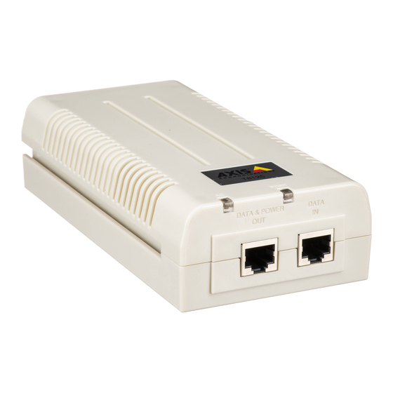
Installing the Unit Verify that the 24 V AC power source is turned off. Connect cables to the AXIS T8125 Input terminal connector (12 AWG for each terminal or 2X16 AWG for each terminal). After connecting the cables to the terminal connector securely tighten all 4 connector screws. - Page 11 AXIS T8125 AC 24 V Midspan 60 W Page 11 2x cable inlet screws Figure 2 2x connector screws Chassis 24 AC Input connection terminal block Terminal connector Figure 3 AC input connectivity Port connectivity indication (Main LED) indication (Port LED)
-
Page 12: Specifications
Page 12 AXIS T8125 AC 24 V Midspan 60 W Indicators Main LED Green Power OFF indication Power ON indication (power is active) Green Port LED Behavior Disconnected. No connection or no load is connected Power supplied over data and spare pairs... -
Page 13: Troubleshooting
AXIS T8125 AC 24 V Midspan 60 W Page 13 Troubleshooting Symptom Corrective Steps Remove and re-apply power to the device and check the indicators during power up sequence. The AXIS T8125 Verify that the voltage at the power inlet is in the range does not power up. -
Page 14: Warranty
Page 14 AXIS T8125 AC 24 V Midspan 60 W Warranty For information about Axis' product warranty and thereto related information, see www.axis.com/warranty... -
Page 15: Mesures De Sécurité
• Conservez le produit Axis dans un environnement sec et aéré. • Évitez d'exposer le produit Axis aux vibrations, aux chocs ou à une forte pres- sion. N'installez pas le produit sur un support instable, ou des surfaces ou des murs instables ou vibrants, car cela pourrait l'endommager. -
Page 17: Guide D'installation
Remarque : Ne pas raccorder la mise à la terre du châssis à la « prise de terre » ne constitue pas un risque de sécurité. • La source électrique CA 24 V doit se trouver à proximité de l’AXIS T8125 et être facile d’accès. Pour couper l’alimentation CA de l’AXIS T8125, débranchez le cordon d’alimentation CA 24 V de la... -
Page 18: Instructions De Montage
Instructions de montage L’AXIS T8125 peut être placé sur un bureau ou fixé sur un mur/banc à l’aide des fentes de montage situées au dos de l’AXIS T8125. Posez deux vis (non incluses) au mur ou sur l’étagère comme indiqué... - Page 19 AXIS T8125 AC 24 V Midspan 60 W Page 19 1.5 - 2 mm (0.06” - 0.08”) 3 mm 5.8 - 7 mm 91.7 mm (0.12”) (0.23” - 0.27”) (3.61”) 2 mm (0.08”) Dimensions de vis Position des vis Figure 1.
-
Page 20: Fonctions Et Caractéristiques
• Alt B : 4, 5 (+) et 7, 8 (-) Étapes préliminaires • Vérifiez que l’AXIS T8125 est branché à une alimentation 24 V CA. Utilisez des câbles 12 AWG pour chaque terminal ou 2x16 AWG pour chaque terminal, avec une mise à la terre séparée et appro- priée (le cas échéant). - Page 21 AXIS T8125 AC 24 V Midspan 60 W Page 21 • Il n’y a pas d’interrupteur Marche/Arrêt. Il suffit donc de brancher l’AXIS T8125 sur une source électrique 24 V CA pour le mettre en marche. Mise en garde ! N’utilisez pas de câble croisé...
-
Page 22: Installation De L'unité
Vérifiez que la source électrique 24 V CA est arrêtée. Branchez les câbles au connecteur de terminal d’entrée de l’AXIS T8125 (12 AWG pour chaque terminal ou 2x16 AWG pour chaque terminal). Après avoir branché les câbles au connecteur du terminal, vissez correctement les 4 vis du connecteur. - Page 23 AXIS T8125 AC 24 V Midspan 60 W Page 23 2 vis de câble d’entrée Figure 2 2 vis de connecteur Connexion Bloc terminal de châssis d’entrée 24 V CA Connecteur de terminal Figure 3 Indication de connectivité Indication de connectivité...
-
Page 24: Caractéristiques Techniques
Page 24 AXIS T8125 AC 24 V Midspan 60 W Indicateurs OFF (éteinte) Vert principale Indication d’alimenta- Indication d’alimentation branchée Vert tion coupée (l’appareil est sous tension) DEL de port Comportement Déconnecté. Pas de connexion ou charge non OFF (éteinte) connectée... -
Page 25: Dépannage
AXIS T8125 AC 24 V Midspan 60 W Page 25 Interface Ethernet Connecteur femelle RJ45 Entrée (données d’entrée) Connecteur femelle RJ45, avec ten- Sortie (données et alimentation de sortie) : sion CC sur les paires de fils 1-2, Ethernet 10/100/1000Base-T, plus 55 V CC 3-6, 4-5 et 7-8. -
Page 26: Garantie
Page 26 AXIS T8125 AC 24 V Midspan 60 W Garantie Pour plus d'informations sur la garantie des produits Axis et des informations générales relatives à celle-ci merci de consulter le site www.axis.com/warranty... - Page 27 • Verwenden Sie dieses Axis-Produkt unter Beachtung der vor Ort geltenden rechtlichen Bestimmungen. • Um dieses Axis-Produkt im Freien verwenden zu können, muss es in einem zugelassenen Außengehäuse installiert werden. • Das Axis Produkt sollte nur von geschultem Fachpersonal installiert werden.
- Page 29 V-Wechselstromanschluss entweder von der 24-V-Wechselstrom- quelle oder vom AXIS T8125-Wechselstromanschluss ab, um den AXIS T8125 von der Wechselstromquelle zu trennen. • Die AXIS T8125-Schnittstellen DATA IN und DATA & POWER OUT sind SELV-Stromkreise (mit Sicherheitskleinspannung) nach IEC 60950-1. Diese Schnittstellen können nur an SELV-Schnittstellen anderer Geräte angeschlossen werden.
- Page 30 • Achten Sie beim Anschließen der Netzanschlussklemmen darauf, dass sie nicht die Gehäuseerde berühren. Montageanweisungen Der AXIS T8125 kann auf einem Schreibtisch stehen oder mithilfe der Montageschlitze auf der Rückseite des AXIS T8125 an einem Tisch oder einer Wand angebracht werden.
- Page 31 AXIS T8125 AC 24 V Midspan 60 W Seite 31 1.5 - 2 mm (0.06” - 0.08”) 3 mm 5.8 - 7 mm 91.7 mm (0.12”) (0.23” - 0.27”) (3.61”) 2 mm (0.08”) Schraubenmaße Schraubenpositionierung Abbildung 1...
-
Page 32: Funktionen Und Merkmale
• Prüfen Sie, dass ein netzstromfähiges, Ethernet-kompatibles Gerät angeschlossen ist. • Decken Sie den AXIS T8125 nicht ab und behindern Sie den Luft- strom zum PoE nicht durch Fremdobjekte. Setzen Sie den AXIS T8125 keiner übermäßigen Hitze und Feuchtigkeit aus, und vermei- den Sie Vibrationen, Staub und direkte Sonneneinstrahlung. - Page 33 AXIS T8125 AC 24 V Midspan 60 W Seite 33 • Es gibt keinen Netzschalter. Schließen Sie den AXIS T8125 einfach an eine 24-V-Wechselstromquelle an. Vorsicht! Verwenden Sie kein Crossoverkabel zwischen dem Port des AXIS T8125 und dem Gerät, das mit Strom...
-
Page 34: Installieren Des Geräts
Seite 34 AXIS T8125 AC 24 V Midspan 60 W Installieren des Geräts Prüfen Sie, dass die 24-V-Wechselstromquelle ausgeschaltet ist. Verbinden Sie Kabel mit den AXIS T8125-Eingangsklemmen (12 AWG oder 2X16AWG für jede Klemme). Ziehen Sie alle 4 Anschlussschrauben fest an, wenn Sie die Kabel mit den Klemmen verbunden haben. - Page 35 AXIS T8125 AC 24 V Midspan 60 W Seite 35 2 Kabeleingangs- schrauben Abbildung 2 2 Anschlussschrauben Gehäuse- 24-V-Anschlussblock für anschluss Wechselstromeingang Anschlussleiste Abbildung 3 Wechselstromeingangs- Port-Anschlussanzeige anzeige (Haupt-LED) (Port-LED) Abbildung 4 Eingangsport Ausgangsport (DATA IN) (DATA & POWER OUT)
-
Page 36: Technische Daten
Seite 36 AXIS T8125 AC 24 V Midspan 60 W Anzeigen Haupt-LED Grün Anzeige Strom AUS Anzeige Strom EIN (Strom ist einge- Grün schaltet) Port-LED Verhalten Nicht verbunden. Keine Verbindung oder kein zu versor- gendes Gerät angeschlossen Stromversorgung erfolgt über Daten- und nicht belegte Grün EIN... -
Page 37: Fehlerbehebung
AXIS T8125 AC 24 V Midspan 60 W Seite 37 Ethernet-Schnittstelle RJ45-Buchse Eingang (DATA IN) RJ-45-Buchse mit Gleichspannung Ausgang (DATA & POWER OUT): auf den Kabelpaaren 1-2 und 3-6, Ethernet 10/100/1000Base-T, plus 55 V 4-5 und 7-8. Gleichstrom Fehlerbehebung Problem Abhilfemaßnahmen... -
Page 38: Gewährleistung
Seite 38 AXIS T8125 AC 24 V Midspan 60 W Gewährleistung Die Garantiebedingungen für Axis Produkte sowie weitere Informationen zum Thema Garantie finden Sie unter www.axis.com/warranty... - Page 39 • Conservare il prodotto Axis in un ambiente asciutto e ben ventilato. • Evitare di esporre il prodotto Axis alle vibrazioni, agli urti o a forte pressione. Non installare il prodotto su staffe instabili, superfici o pareti instabili o vibranti, poiché...
-
Page 41: Guida All'installazione
Guida all’installazione Informazioni sulla sicurezza Set di ingressi di alimentazione c.a.: • Il connettore elettrico fornito con AXIS T8125 è dotato di 2 termi- nali. Vedere figura 2. • I cavi di alimentazione elettrica devono essere idonei a una capa- cità... -
Page 42: Istruzioni Di Montaggio
Istruzioni di montaggio AXIS T8125 può essere posizionata su una scrivania o installata su una parete o un banco utilizzando le cavità di montaggio sul retro dell’unità AXIS T8125. - Page 43 AXIS T8125 AC 24 V Midspan 60 W Pagina 43 1.5 - 2 mm (0.06” - 0.08”) 3 mm 5.8 - 7 mm 91.7 mm (0.12”) (0.23” - 0.27”) (3.61”) 2 mm (0.08”) Dimensioni delle viti Posizione delle viti Figura 1...
-
Page 44: Funzioni E Caratteristiche
• Alt B: 4, 5 (+) e 7, 8 (-) Operazioni preliminari • Assicurarsi di collegare 24 V c.a. a AXIS T8125. Usare cavi da 12 AWG per ciascun terminale o 2X16 AWG per ciascun terminale, con un idoneo collegamento di messa a terra separato (se necessario). - Page 45 AXIS T8125 AC 24 V Midspan 60 W Pagina 45 Attenzione! Non usare cavi incrociati tra la porta di uscita di AXIS T8125 e il dispositivo di carico.
-
Page 46: Installazione Dell'unità
Verificare che la sorgente di alimentazione a 24 V c.a. sia disattivata. Collegare i cavi al connettore del terminale di ingresso di AXIS T8125 (12 AWG per ciascun terminale o 2X16 AWG per ciascun terminale). Dopo aver collegato i cavi al connettore del terminale, serrare saldamente tutte le 4 viti del connettore. - Page 47 AXIS T8125 AC 24 V Midspan 60 W Pagina 47 2x viti di ingresso cavo Figura 2 2x viti connettore Collegamen Morsettiera per to telaio ingressi 24 c.a. Connettore terminale Figura 3 Indicatore connettività Indicatore connettività ingresso c.a. (LED principale) porta (LED porta).
-
Page 48: Indicatori Luminosi
Pagina 48 AXIS T8125 AC 24 V Midspan 60 W Indicatori luminosi SPENTO Verde principale Indicatore alimenta- Indicatore alimentazione ACCESA (ali- Verde zione SPENTA mentazione attiva) LED porta Comportamento Scollegato. Nessuna connessione o nessun carico con- SPENTO nesso Alimentazione fornita su dati e coppie libere ACCESO verde La porta è... -
Page 49: Risoluzione Dei Problemi
AXIS T8125 AC 24 V Midspan 60 W Pagina 49 Interfaccia Ethernet Connettore femmina RJ45 Ingresso (DATA IN) Connettore femmina RJ45 con Uscita (DATA & POWER OUT): tensione a c.c. sulle coppie di cavi Ethernet 10/100/1000Base-T, plus 55 V c.c. -
Page 50: Garanzia
Pagina 50 AXIS T8125 AC 24 V Midspan 60 W Garanzia Per informazioni relative alla garanzia del prodotto AXIS ed ogni altra ulteriore informazione correlata, si prega di consultare la pagina www.axis.com/warranty... -
Page 51: Medidas Preventivas
• La instalación del producto Axis debe realizarla un profesional cualificado. Siga las normativas nacionales y locales aplicables para la instalación. Transporte • A la hora de transportar el producto Axis, utilice el embalaje original o uno equivalente para no dañar el producto. -
Page 53: Guía De Instalación
No existe ningún riesgo de seguridad cuando la conexión a tierra del chasis no está conectada a la "Puesta a tierra". • La fuente de alimentación de 24 V de CA debe estar cerca del AXIS T8125 y ser accesible fácilmente. Para retirar la alimentación de CA del AXIS T8125, desconecte la entrada de alimentación de 24... -
Page 54: Instrucciones De Montaje
• Una tensión incorrecta puede causar daños al equipo y provocar un riesgo de incendio. Si la tensión indicada en la etiqueta es distinta de la tensión de la toma de alimentación, no conecte el AXIS T8125 a la toma de alimentación. - Page 55 AXIS T8125 AC 24 V Midspan 60 W Página 55 1.5 - 2 mm (0.06” - 0.08”) 3 mm 5.8 - 7 mm 91.7 mm (0.12”) (0.23” - 0.27”) (3.61”) 2 mm (0.08”) Dimensiones del tornillo Colocación de los tornillos...
-
Page 56: Funciones Y Características
• Compruebe que haya conectado un dispositivo compatible con la alimentación a través de Ethernet. • No tape el AXIS T8125 ni bloquee el flujo de aire al PoE con ningún objeto extraño. Mantenga el AXIS T8125 alejado de fuentes de ca- lor y humedad excesivas, así... - Page 57 AXIS T8125 AC 24 V Midspan 60 W Página 57 • Como no hay ningún interruptor de “encendido/apagado”, simple- mente conecte el AXIS T8125 a una fuente de alimentación de 24 V de CA. ¡Precaución! No utilice un cable cruzado para conectar el puerto...
-
Page 58: Instalación De La Unidad
Verifique que la fuente de alimentación de 24 V de CA esté desconectada. Conecte los cables al conector del terminal de entrada del AXIS T8125 (12 AWG para cada terminal o 2x16 AWG para cada terminal). Tras conectar los cables al conector del terminal, apriete firmemente los 4 tornillos del conector. - Page 59 AXIS T8125 AC 24 V Midspan 60 W Página 59 2 tornillos de la entrada del cable Figura 2 2 tornillos del conector Conexión Bloque del terminal del chasis de entrada de 24 CA Conector de terminales Figura 3 Indicación de conectividad de Indicación de conectividad...
-
Page 60: Especificaciones
Página 60 AXIS T8125 AC 24 V Midspan 60 W Indicadores LED principal Apagado Verde Indicación de apagado Indicación de encendido (alimentación Verde activada) LED del puerto Comportamiento Desconectado. Sin conexión o sin carga conectada Apagado Alimentación suministrada a través de datos o pares de... -
Page 61: Solución De Problemas
AXIS T8125 AC 24 V Midspan 60 W Página 61 Interfaz Ethernet Conector hembra RJ45 Entrada (ENTRADA DE DATOS) Conector hembra RJ45, con tensión Salida (SALIDA DE DATOS Y CC en pares de cable 1-2, 3-6, 4-5 ALIMENTACIÓN): y 7-8. - Page 62 Página 62 AXIS T8125 AC 24 V Midspan 60 W Garantía Para información sobre la garantía de productos Axis e información relacionada, por favor consulte www.axis.com/warranty...
- Page 64 Installation Guide Ver.1.1 AXIS T8125 AC 24 V Midspan 60 W Printed: March 2013 © Axis Communications AB, 2012-2013 Part No. 50264...
Need help?
Do you have a question about the T8125 and is the answer not in the manual?
Questions and answers