Clarion WXZ468RMP Service Manual
20din 6-disc cd/mp3/wma receiver /cenet control
Hide thumbs
Also See for WXZ468RMP:
- Owner's manual (44 pages) ,
- Owner's manual (41 pages) ,
- Installation/wire connection manual (4 pages)
Table of Contents
Advertisement
Quick Links
This product is a lead free model.
Lead free solder is used in PWB stamped LF mark.
Please keep the following conditions when you repair.
1. Use lead free solder.
* Koki's lead free solder S3X-55M 0.6mm
(CLARION Parts No.642-0231-01)
* Koki's lead free solder S3X-55M 1.0mm
(CLARION Parts No.642-0231-02)
2. Use a nitrogen solder system.
3. Do not use "General solder" and "Lead free solder"
together.
NOTES
*
As for this model, CCC-TUNER is used.
When you exchange it due to the tuner pack (BL1:880-
2150A) trouble, it is necessary to adjust for S-meter etc.
Special JIG is necessary for an accurate adjustment.
The procedure document for the exclusive use jig is ap-
pended to it.
*
Use only compact discs bearing the
*
Some CDs recorded in CD-R/CD-RW mode may not be
usable.
*
This product includes technology owned by Microsoft
Corporation and cannot be used or distributed without a
license from MSLGP.
*
and
or registered trademarks of Microsoft Corporation in the
United States and/or other countries.
*
We cannot supply PWB with component parts in prin-
ciple. When a circuit on PWB has failure, please repair it
by component parts base. Parts which are not mentioned
in service manual are not supplied.
*
Specifications and design are subject to change without
notice for further improvement.
Clarion Co., Ltd.
50 Kamitoda, Toda-shi, Saitama 335-8511 Japan
Service Dept.: 5-66 Azuma , Kitamoto-shi, Saitama 364-0007 Japan
Tel: +81-48-541-2335 / 2432 FAX: +81-48-541-2703
Service Manual
or
mark.
logo are trademarks
- 1 -
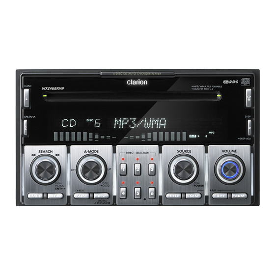
2-DIN 6-disc
CD/MP3/WMA Receiver
/ CeNET Control
Model
(PE-2758E)
SPECIFICATIONS
Radio section
Tuning system:
PLL frequency synthesizer system
Receive range:
FM 87.5MHz to 108MHz
(0.05MHz steps)
MW 531kHz to 1,602kHz
(9kHz steps)
LW 153kHz to 279kHz
(3kHz steps)
CD player section
System:
Compact disc digital audio system
Usable discs:
Compact disc
Frequency response:
10Hz to 20kHz(+/-1dB)
Signal to noise ratio:
90dB(1kHz)
Dynamic range:
90dB(1kHz)
Harmonic distortion:
0.01%
Channel separation:
75dB(1kHz)
MP3/WMA mode:
MP3 ; Sampling rate 11.025kHz -
48kHz
Bit rate : 8kbps - 320kbps / VBR
WMA;Bit rate;48kbps-192kbps/VBR
Logical format(File system);
ISO9660 level 1, 2 or JOLIET or
Romeo
Audio amplifier section
Output power:
27W x 4ch (DIN 45324, +B=14.4V)
Continuous average power output:
17W x 4ch
(4 ohm, 20Hz to 20kHz, 1%THD)
Bass control action:
+14dB, -12dB(60Hz/80Hz/120Hz)
Treble control action:
+/-12dB(8kHz/12kHz)
9 Band-G-EQ:
1 oct step GAIN +/-12dB
(63Hz to 16kHz)
Line output level:
1.8V(CD 1kHz)
General
Power supply voltage: 14.4V DC
(10.8V to 15.6V allowable)
Ground:
Negative
Current consumption: Less than 15A, 3A
Speaker impedance:
4 ohm(4 ohm to 8 ohm)
Dimensions(mm):
178(W) x 100(H) x 160(D)
Weight:
2.3kg
Published by Service Dept.
298-6340-00 Feb.2006
Printed in Japan
WXZ468RMP
Advertisement
Table of Contents

Related Manuals for Clarion WXZ468RMP


Summary of Contents for Clarion WXZ468RMP
-
Page 1: Specifications
Clarion Co., Ltd. Published by Service Dept. 50 Kamitoda, Toda-shi, Saitama 335-8511 Japan 298-6340-00 Feb.2006 Service Dept.: 5-66 Azuma , Kitamoto-shi, Saitama 364-0007 Japan Printed in Japan Tel: +81-48-541-2335 / 2432 FAX: +81-48-541-2703 Service Manual 2-DIN 6-disc CD/MP3/WMA Receiver / CeNET Control... -
Page 2: To Engineers In Charge Of Repair Or Inspection Of Our Products
5. Cautions in soldering Please do not spread liquid flux in soldering. Please do not wash the soldering point after soldering. WXZ468RMP - 2 -... -
Page 3: Notes Of Iso Connector
4. Press the [ADJ] button to return to the previous mode. Blue/White Blue/White Auto ant.(A-5) Remote turn-on Insulate the terminal Never let the terminals make contact with the metal plate parts of the car. Figure 2 - 3 - WXZ468RMP... -
Page 4: Troubleshooting
ERROR R Region code error Eject the disc and replace correct region code disc. If an error display other than the ones described above appears, press the reset button. If the problem persists, turn off the power. WXZ468RMP - 4 -... -
Page 5: Self-Diagnosis Function
Error frequency confirmation 1. Press the [2] button for one second or more at the error history confirmation mode. Display : " T01 * * * * * " The number of times at error - 5 - WXZ468RMP... -
Page 6: Measuring Instrument
: " Hard___*** " 2. The adjustment band is automatically set by the main microcomputer of the unit and memorized in EEPROM in CCC-TUNER. 3. Press the reset button of the unit to set the data. WXZ468RMP - 6 -... - Page 7 : O : The clock pulse output to the VFD driver. pin 53: CTRL : O : Power supply ON signal output. pin 54: INT AMP REM : O : ON signal output to the internal Amplifier. pin 55: NU : IN : Not in use. - 7 - WXZ468RMP...
-
Page 8: Block Diagram
BLOCK DIAGRAM MAIN MICOM UPD703272YGC (IC601) (BL1) CCC-TUNER 880-2150A CHANGER MECHANISM WXZ468RMP - 8 -... -
Page 9: Exploded View Parts List
335-7553-00 ILLUMI PLATE(B) 347-7877-00 FILM(D) 335-7557-00 ILLUMI PLATE(L) 347-7876-00 FILM(C) 335-7556-00 ILLUMI PLATE(R) 347-7875-00 FILM(B) 346-0180-00 LEATHER SHEET 347-7874-00 FILM(A) 371-5832-01 TRIM PLATE 347-7321-00 E-SHEET 335-7551-00 ILLUMI PLATE(CD) 345-5598-00 CUSHION 335-7561-00 ILLIMI-PLATE(A) 347-6548-00 DOUBLE FACE 335-7555-00 ILLUMI PLATE(B) - 9 - WXZ468RMP... -
Page 10: Main Section
780-3006-51 SCREW(M3 x 6) 341-1823-00 SHAFT-S 714-2610-8B MACHINE SCREW(M2.6 x 10) 347-7229-00 SPACER FILM 716-3552-00 SCREW(M2.3 x 2.5) 076-0648-22 PLUG(22P) 060-6028-00 DC-DC CONVERTER 076-0648-10 PLUG(10P) 335-0833-01 LEAD HOLDER ----------- MAIN PWB 855-0569-52 MINI JACK CORD 073-0762-90 TERMINAL 880-2150A CCC-TUNER WXZ468RMP - 10 -... -
Page 11: Electrical Parts List
168-1042-78 16V 0.1uF C110 178-4742-78 0.47uF C303 168-1032-55 0.01uF K C340 168-4732-78 0.047uF K C116 168-1022-55 1000pF K C304 168-1032-55 0.01uF K C341 168-4732-78 0.047uF K C125 168-1022-55 1000pF K C305 187-4753-55 35V 4.7uF C401 168-1042-78 16V 0.1uF - 11 - WXZ468RMP... - Page 12 119-4721-15 1/10W 4.7k ohm C613 166-3911-50 390pF CH IC602 051-6600-58 HA12187FP 119-1041-15 1/10W 100k ohm C614 187-1073-35 16V 100uF IC603 051-5446-08 BD4843G-TR R101 119-1031-15 1/10W 10k ohm C615 042-1596-00 5.5V 0.33F IC604 051-5410-18 S-80820CNMC-8BF R102 119-2731-15 1/10W 27k ohm WXZ468RMP - 12 -...
-
Page 13: Connector Layout
ISO CONNECTOR BLACK R454 119-2231-15 1/10W 22k ohm R624 119-5621-15 1/10W 5.6k ohm B7 B8 A7 A8 A5 A6 B3 B4 PHONE BROWN MUTE B1 B2 ORG / WHT YELLOW FUSE(3A) BACK UP 120-0030-00 YELLOW FUSE(15A) 120-0150-00 - 13 - WXZ468RMP... -
Page 14: Circuit Diagram
S703 S707 S711 S715 KEY-INT R745 SPE/ANA BAND SYS +5V R746 ACC 3.3V S704 S708 S712 S716 R747 KEY-ILL DISP IC701 R737 R736 VR704(2/2) VR703(2/2) LC75700T 2.7K VR704(1/2) << G.EQ R728 R729 >> SEARCH D721 MA111 - 14 - WXZ468RMP... -
Page 15: Printed Wiring Board
Switch PWB(B1) section COMPONENT SIDE SOLDER SIDE Caution: COMPONENT SIDE: Parts on the component side seen from the component side are indicated. SOLDER SIDE: Parts on the solder side seen from the solder side are indicated. WXZ468RMP - 15 -... - Page 16 COMPONENT SIDE: Parts on the component side seen from the component side are indicated. Flat wire 816-4023-50 To page M16 To page 15 To page 15 J1 of CD changer mechanism J701 of Switch PWB J702 of Switch PWB - 16 - WXZ468RMP...
- Page 17 15 BACK UP 16 GND 7 R-CH(+) SOLDER SIDE Caution: SOLDER SIDE: Parts on the solder side seen from the solder side are indicated. The parts of a dotted line express the parts on a component side. - 17 - WXZ468RMP...
- Page 18 To page 19 V_DO F-GND WIRED VFD_DO AUDIO 9V Main PWB 2/3 V_BLK REMOCON VFD_BLK V_LAT F-GND VFD_LAT To page 19 FILA1 FILA1 To page 20 Main PWB 2/3 FILA2 FILA2 Main PWB 3/3 47.6V D/D-GND D/D-GND - 18 - WXZ468RMP...
- Page 19 C568 3.9K 2.2 50V IC401 BA3834F L401 INPL C569 5.0V R575 R578 2.2 50V 3.9K PLOUT C579 C505 R584 C507 10 16V 2200p 8.2K 270p R562 VOUTL R576 C572 D554 C570 10 16V MA111 2.2 50V - 19 - WXZ468RMP...
- Page 20 14 BACK UP(BUS) D504 R536 C131 C105 0.47 R114 ILL OFF:0V HZU7.5B2 1000p 15 BACK UP 16 GND C103 0.47 R115 C116 13.3V 6.0V 1000p C132 14.0V 1000p 14.0V D203 1N5404 BUS 14V L101 B/U 14V - 20 - WXZ468RMP...
- Page 21 Clarion Co., Ltd. Published by Service Dept. 50 Kamitoda, Toda-shi, Saitama 335-8511 Japan Jan.2006 Service Dept.: 5-66 Azuma , Kitamoto-shi, Saitama 364-0007 Japan Printed in Japan Tel: +81-48-541-2335 / 2432 FAX: +81-48-541-2703 Service Manual In Dash 6disc CD Auto Changer...
- Page 22 pin 38: Po 9 : O : General-purpose output terminal. 052-5070-91 T5AF4 Mechanism Controller pin 39: Po 8 : O : General-purpose output terminal. pin 40: VDDM : - : Positive voltage supply. TerminalDescription pin 41: SRMSTB : IN : Internal SRAM I/F. Standby input. 1: Vref L : - : Reference voltage.
- Page 23 pin 65: BUS 0 :I/O: CD IC Data input / output. pin 66: BUS 1 :I/O: CD IC Data input / output. pin 67: BUS 2 :I/O: CD IC Data input / output. pin 68: BUS 3 :I/O: CD IC Data input / output. pin 69: CCE : O : The chip enable signal output.
- Page 24 DISASSEMBLY How to remove "CD-PWB-ASSY" How to remove "DISCHOLDER UNIT" 1. Add +5V to "U+" terminal of UD-MOTOR-ASSY,then 1. Remove eight screws. SIDE-P-ASSY-F moves outside of CD-PWB. 2. Remove the FPC. 2. Release four FPCs. 3. Remove three screws 4. Remove the washer. 5.
- Page 25 How to remove "N-DRIVE UNIT" How to remove "LO-MOTOR-S-ASSY" 1. Remove the screw and DRIVE SPRING-A. 1. Remove two screws and DRIVE CHASSIS-B. 2. Rotate N-DRIVE UNIT internally. 2. Remove the screw of the bottom side. 3. Remove the washer, and remove N-DRIVE UNIT. 3.
-
Page 26: Operation
OPERATION Discholder MOT2 (Mode Motor) S1 of CD-PWB (Mode Plate) S2 of CD-PWB (Mode Plate) Drive Unit S3 of CD-PWB (Mode Plate) MOT3 (UP/DW-Motor) S5 of SENSOR-U-FPC (Sutter) MOT1 (Loading Motor) S4 of CD-PWB (Holder) Loading Roller Shutter PT3 of SENSOR-L-FPC PT2 of SENSOR-L-FPC PT1 of SENSOR-L-FPC IC10 of CD PWB... - Page 27 EXPLODED VIEW/PARTS LIST Main section to C2 to C4 to C3 to D3 to B1 to B2 to C1 to A6 to A7 33 34 to A3 to A5 to A2 to A4 to D3 21 14 * Do not reuse the following parts. (No.24,25,28,29,30,31,32) PART NO.
-
Page 28: Lower Unit Assy Section
Lower unit assy section to A1 to A2 to A3 to A5 to A7 to A6 PART NO. DESCRIPTION Q'TY PART NO. DESCRIPTION Q'TY 620-1771-22 CAM GEAR 966-1757-21 LOWER-C-ASSY 620-1624-24 GEAR COVER 966-0658-21 DH-SP-ASSY A 621-0732-21 M-GEAR B 966-1758-20 DS-SP-ASSY A 621-0733-20 M-GEAR C 966-0660-22 DH-SP-ASSY S 716-1850-01 SCREW(M2.0x2.0) - Page 29 [ Grease Point ] * Grease: SANKOL FG-87HSR Put grease on the surface Put grease on the reverse side Put grease on the both sides Put grease on the edge - M9 - 929-0371-80...
-
Page 30: N-Drive-Ch Unit Section
N-Drive-CH unit section to A2 to A1 to B1 to A3 to A4 * Do not reuse the following parts. (No.17,18,19,20) PART NO. DESCRIPTION Q'TY PART NO. DESCRIPTION Q'TY HBS-565-100 N-DRIVE UNIT 716-3450-00 SCREW(M1.7x2.0) HBS-567-100 LOADING-U-ASSY 716-3459-01 SCREW(M1.7x2.0) HBS-556-100 LO-MOTOR-S-ASSY 750-6761-20 DRIVE SPRING A HBS-552-100 L-SENSOR-S-ASSY 345-5868-00 RUBBER PART... - Page 31 [ Grease Point ] * Grease A: SANKOL FG-87HSR * Grease B: SANKOL CFD-006MBL Put grease on the surface Put grease on the reverse side Put grease on the both sides Put grease on the edge Surface of PIN Surface of Spring - M11 - 929-0371-80...
-
Page 32: Upper Unit Assy Section
Upper unit assy section to A1 * Do not reuse the following parts. (No.7,8,10) PART NO. DESCRIPTION Q'TY to A2 966-1761-21 UPPER-CHA-ASSY 966-1765-20 LO-SHIFT A ASSY 966-0700-22 LO-SHIFT B ASSY 966-0701-21 LO-SHIFT ASSY 966-1766-20 SHUTTER-PL-ASSY 966-1763-20 SHUTTER ASSY HBS-553-100 U-SENSOR-S-ASSY ----------- SENSOR-U-FPC 347-7272-00 RATTLE SHEET... - Page 33 ELECTRICAL PARTS LIST CD PWB(BM1) section REF No. PART No. DESCRIPTION REF No. PART No. DESCRIPTION REF No. PART No. DESCRIPTION 042-0672-00 25V 47uF TA 178-1052-78 1uF 119-4731-15 1/10W 47k ohm 166-1011-50 100pF CH 168-1045-56 0.1uF Z 119-2231-15 1/10W 22k ohm 168-1042-78 16V 0.1uF 168-2222-55 2200pF K 119-2231-15 1/10W 22k ohm...
- Page 34 BLOCK DIAGRAM 929-0371-80 - M14-...
-
Page 35: Circuit Diagram
CIRCUIT DIAGRAM CD PWB(BM1) section Sensor-L-FPC(BM2) section Sensor-U-FPC(BM3) section 2SB1427 2SB1427 3.3V CD3.3 074-1237-69 9.0V CD-9V CD-9V 47 10V TAN 3.3V 16.92M 3.3V 3.3V SYS-ACC 3.3V TP14 0.047 470p 2SB1188 3.3V 2SB1188 Drive Unit A-MUTE MOT3 3.3V UP/DOWN 6800p 3.0V (V-MOTOR) SPDIF 0.047... - Page 36 PRINTED WIRING BOARD CD PWB(BM1) section Sensor-L-FPC(BM2) section Sensor-U-FPC(BM3) section Drive Unit MOT3 Up/Dw To Main PWB CD PWB(BM1) section CD PWB(BM1) section SOLDER SIDE COMPONENT SIDE MOT1 Loading Sensor-L-FPC(BM2) section MOT2 Mode Sensor-U-FPC(BM3) section LED1 Caution: COMPONENT SIDE: Parts on the component side seen from the component side are indicated.
Need help?
Do you have a question about the WXZ468RMP and is the answer not in the manual?
Questions and answers