Table of Contents
Advertisement
INSTALLATION INSTRUCTION
208/230/460
VOLT ONLY
SAFETY CONSIDERATIONS
Due to system pressure, moving parts and electrical
components, installation and servicing of air conditioning
equipment can be hazardous. Only qualified, trained, service
personnel should install, repair, maintain or service this
equipment.
Observe all precautions in the literature, on labels and tags
accompanying the equipment whenever working on air
conditioning equipment. Be sure to follow all other safety
precautions that apply.
Wear safety glasses and work gloves, and follow all safety
codes. Use a quenching cloth and have a fire extinguisher
available for all brazing operations.
GENERAL
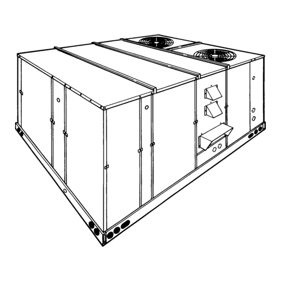
YORK Model DCG units are single package gas-fired central
heating furnaces with cooling unit designed for outdoor
installation on a rooftop or a slab.
The units are completely assembled on rigid, permanently
attached base rails. All piping, refrigerant charge, and electrical
wiring is factory installed and tested. The units require electric
power, gas connection, duct connections, installation of
combustion air inlet hood, flue gas outlet hoods and fixed
outdoor air intake damper (units without economizer or
motorized damper option only) at the point of installation.
FOR YOUR SAFETY
If you smell gas:
1. Open windows.
2. Don't touch electrical switches; do not use
any phones in the area of the gas leak.
3. Extinguish any open flame.
4. Immediately call your gas supplier from another
location. Follow your gas supplier's
instructions.
5. If you cannot reach your gas supplier, call the
fire department.
Do not store or use gasoline or other flammable vapors and
liquids in the vicinity of this or any other appliance.
Installer should pay particular attention to the words: NOTE, CAUTION and WARNING. Notes are intended to clarify or make
the installation easier. Cautions are given to prevent equipment damage. Warnings are given to alert installer that personal injury
and/or equipment damage may result if installation procedure is not handled properly.
Supersedes: 530.18-N6Y (1298)
MODELS D2CG180 & 240 (STY. B)
FOR YOUR SAFETY
SUNLINE 2000
GAS / ELECTRIC
SINGLE PACKAGE AIR CONDITIONERS
(8.4 - 8.5 EER)
The gas-fired heaters have aluminized-steel tubular heat
exchangers and spark ignition with proven pilot.
INSPECTION
As soon as a unit is received, it should be inspected for possible
damage during transit. If damage is evident, the extent of the
damage should be noted on the carrier's freight bill. A separate
request for inspection by the carrier's agent should be made in
writing. Refer to Form 50.15-NM for additional information.
REFERENCE
Additional information on the design, installation, operation and
service of this equipment is available in the following reference
forms:
•
44-320-10
•
530.18-N6.1V - Propane Conversion Accessory (USA)
•
530.18-N6.2V - High Altitude Accessory (Nat. Gas)
•
530.18-N6.3V - High Altitude Accessory (Propane)
•
530.18-N13Y
Renewal Parts:
•
Refer to the Renewal Parts Manual for complete listing of
replacement parts on this equipment.
All forms referenced in this instruction may be ordered from:
Standard Register
2101 West Tecumeseh Road
Norman, Oklahoma 73069
Toll Free Fax: (877) 379-7920
Toll Free Phone: (877) 318-9675
APPROVALS
Design certified by ETL & CGA as follows:
1. For use as a forced air furnace with cooling unit.
2. For outdoor installation only.
3. For installation on combustible material.
4. For use with natural gas or propane gas.
THIS PRODUCT MUST BE INSTALLED IN STRICT COMPLIANCE
WITH THE ENCLOSED INSTALLATION INSTRUCTIONS AND ANY
APPL ICABL E L OCAL, STATE, AND NATIONAL CODES
INCLUDING, BUT NOT LIMITED TO, BUILDING, ELECTRICAL,
AND MECHANICAL CODES.
INCORRECT INSTALLATION MAY CREATE A CONDITION
WHERE THE OPERATION OF THE PRODUCT COULD CAUSE
PERSONAL INJURY OR PROPERTY DAMAGE
530.18-N6Y (500)
- Barometric Relief Damper Accessory
- Coil Guard Installation
CAUTION
WARNING
035-12552
208/230/575
VOLT ONLY
Advertisement
Table of Contents

Related Manuals for York D2CG180 & 240 (STY. B)


Summary of Contents for York D2CG180 & 240 (STY. B)
- Page 1 530.18-N6.1V - Propane Conversion Accessory (USA) GENERAL • 530.18-N6.2V - High Altitude Accessory (Nat. Gas) • YORK Model DCG units are single package gas-fired central 530.18-N6.3V - High Altitude Accessory (Propane) • heating furnaces with cooling unit designed for outdoor 530.18-N13Y - Coil Guard Installation installation on a rooftop or a slab.
-
Page 2: Table Of Contents
530.18-N6Y TABLE OF CONTENTS General ................1 MAINTENANCE & TROUBLESHOOTING Inspection................1 Normal Maintenance ............20 Reference................1 Cleaning Flue Passages and Heating Elements ....20 Approvals ................1 Troubleshooting..............21 Nomenclature............... 2 Replacement Parts ............23 INSTALLATION TABLES Limitations................3 Description Page Location ................ -
Page 3: Installation
CAUTION: If a unit is to be installed on a roof curb or special national and local safety codes: frame other than a YORK roof curb, gasketing must In U.S.A.: be applied to all surfaces that come in contact with 1. -
Page 4: Ductwork
530.18-N6Y DUCTWORK Ductwork should be designed and sized according to the methods in Manual Q of the Air Conditioning Contractors of America (ACCA). A closed return duct system shall be used. This shall not preclude use of economizers or outdoor fresh air intake. The supply and return air duct connections at the unit should be made with flexible joints to minimize noise. -
Page 5: Thermostat
530.18-N6Y FIG. 5 - TYPICAL FIELD WIRING THERMOSTAT replacement wire must be of the type shown on the wiring diagram and the same minimum gauge as the replaced wire. The room thermostat should be located on an inside wall approximately 56 inches above the floor where it will not be Electrical line must be sized properly to carry the load. -
Page 6: Combustion Discharge
530.18-N6Y lie below the bottom gas manifold to avoid interference with the TABLE 3 - GAS HEAT APPLICATION DATA burner assembly. Input Capacity (Mbh) Output Capacity (Mbh) Two grommets are shipped in the blower compartment (in parts Temp. 0 To 2,000 To 0 To 2,000 To... -
Page 7: Vent And Combustion Air Hoods
530.18-N6Y VENT AND COMBUSTION AIR HOODS Two vent hoods and a combustion air hood (with screens) are shipped attached to the blower housing in the blower compartment. These hoods must be installed to assure proper unit function. All hoods must be fastened to the outside of the gas heat access panel with the screws provided in the bag also attached to the blower housing. - Page 8 530.18-N6Y FIG. 9 - ENTHALPY SETPOINT ADJUSTMENT Unitary Products Group...
-
Page 9: Physical Data
530.18-N6Y TABLE 5 - PHYSICAL DATA UNIT SIZE OPERATING WEIGHTS (LBS.) 15 TON 20 TON MODELS 15 TON 20 TON 240 Mbh 2100 2300 Basic Unit 320 Mbh 2140 2340 CENTRIFUGAL BLOWER (Dia. x Wd. in.) 15 x 15 18 x 15 EVAPORATOR BLOWER FAN MOTOR HP... -
Page 10: Electrical Data
530.18-N6Y TABLE 6 - ELECTRICAL DATA COMPRESSORS COND. FAN SUPPLY AIR MINIMUM MAXIMUM MOTORS BLOWER POWER CIRCUIT TIME DELAY (#1 & #2) MOTOR MODEL SUPPLY AMPACITY FUSE SIZE (AMPS) (AMPS) RLA LRA RLA LRA EACH EACH 208/230-3-60 38.4 248 19.2 124 4.1 / 4.2 15.4 / 14.4 87.1 / 84.9... - Page 11 530.18-N6Y RETURN AIR SUPPLY AIR CONDENSER AIR OUTDOOR AIR (Economizer) All dimensions are in inches. They are sub- ject to change without notice. Certified di- mensions will be provided upon request. UTILITIES ENTRY DATA OPENING HOLE SIZE USED FOR (DIA.) 1-1/8"...
-
Page 12: Four And Six Point Loads
530.18-N6Y 4 POINT LOADS 6 POINT LOADS FIG. 11 - FOUR AND SIX POINT LOADS TABLE 7 - FOUR AND SIX POINT LOADS UNIT 4 - POINT LOADS (LBS) TOTAL 2300 2500 NOTE: These weights are with economizer, and the largest blower motor available. 6 - POINT LOADS (LBS) UNIT TOTAL... - Page 13 530.18-N6Y TABLE 8 - SUPPLY AIR BLOWER PERFORMANCE (15 TON) - BOTTOM DUCT CONNECTIONS DCG180 MOTOR BLOWER PULLEY 4500 5250 6000 6750 7200 SPEED, (TURNS (RPM) OPEN)* 208 VOLT AND STANDARD DRIVE 6.0** 1010 1040 208 VOLT AND HIGH SPEED DRIVE ACCESSORY 1025 1065 1125...
- Page 14 530.18-N6Y TABLE 9 - SUPPLY AIR BLOWER PERFORMANCE (20 TON) - BOTTOM DUCT CONNECTIONS DCG240 MOTOR BLOWER PULLEY 6000 7000 8000 9000 9400 SPEED, (TURNS (RPM) OPEN)* 208 VOLT AND STANDARD DRIVE 6.0** 1015 208 VOLT AND HIGH SPEED DRIVE ACCESSORY 1025 1050 1065...
-
Page 15: Static Resistances
530.18-N6Y TABLE 10 - STATIC RESISTANCES* EXTERNAL STATIC PRESSURE DROP RESISTANCE, IWG DESCRIPTION 15 TON 20 TON 4500 6000 7200 6000 8000 9400 WET COIL ECONOMIZER OPTION HORIZONTAL DUCT CONNECTIONS *Deduct these resistance values from the available unit ESP values listed in the respective blower performance table except for Horizontal Duct Connections (Shaded ). -
Page 16: Operation
530.18-N6Y OPERATION COOLING SYSTEM ECONOM IZER (SINGLE OR DUAL) WITH POWER EXHAUST - This system operates as specified above with one The cooling section is a complete factory package utilizing an addition. The power exhaust motor is energized whenever the air-cooled condenser. -
Page 17: Safety Controls (Heating)
530.18-N6Y operation until 24V power is removed from the module either 4. Flame Sensor Rod / 100% Ignition Control Lock-Out. The at the unit or by resetting the room thermostat. flame rods and controls are located per Proper Flame Adjust- ment figure. -
Page 18: Pre-Start Check List
530.18-N6Y START-UP PRE-START CHECK LIST inches, nor the operating pressure drop below 5.0" for natural gas units. If gas pressure is outside these limits, Complete the following checks before starting the unit. contact the local gas utility for corrective action. 1. -
Page 19: Burner Air Shutter Adjustment
530.18-N6Y 3. Remove the gas piping closure panel. static pressures. Use Model 1LD0416 for 15 ton units and Model 1LD0417 for 20 ton units. Refer to the Blower Motor and 4. Disconnect wiring to the gas valves and spark ignitors. Drive Data Table. -
Page 20: Adjustment Of Temperature Rise
530.18-N6Y inaccurate. To assure a dry coil, the compressors should be 1. Turn off all other gas appliances connected to the gas meter. deactivated while the test is being run. 2. With the furnace turned on, measure the time needed for 4. -
Page 21: Normal Maintenance
530.18-N6Y MAINTENANCE your particular locality (contact your gas company for explained under “BURNER AIR SHUTTER ADJUSTMENT”. If it is not possible to adjust for the proper flame, the burners may this information - it varies widely from city to city.) need cleaning. -
Page 22: Troubleshooting
530.18-N6Y TROUBLESHOOTING 13. Ensure that all seams on the vent side of the combustion b. If contactor (M3) is pulled in, proceed with the trou- system are air tight. Apply a high temperature (+500°F) bleshooting steps indicated in Step 1 above. sealing compound where needed. - Page 23 530.18-N6Y TROUBLESHOOTING - Cont’d. If lock-out continues to occur, locate the source of the d. If 24 volts is present, remove the pilot burner and problem and correct. remove the pilot orifice from the pilot burner. The orifice is removed in the direction opposite the flow of gas. Inspect the orifice for obstruction.
-
Page 24: Replacement Parts
DAMAGE. CONSULT A QUALIFIED INSTALLER, SERVICE AGENCY OR YOUR LOCAL GAS SUPPLIER FOR INFORMATION OR ASSISTANCE. Unitary Products Group 5005 York Drive, Norman, Oklahoma 73069 Subject to change without notice. Printed in U.S.A Copyright by York International Corporation 2000. All Rights Reserved. Supersedes: 530.18-N6Y (1298) 530.18-N6Y(500) Code: SBY...
Need help?
Do you have a question about the D2CG180 & 240 (STY. B) and is the answer not in the manual?
Questions and answers
What is the weight of a York D2CG300N32046CCA