
Related Manuals for Kenwood TM-G707


Summary of Contents for Kenwood TM-G707
-
Page 1: Instruction Manual
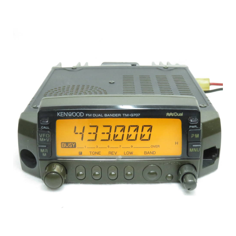
INSTRUCTION MANUAL 144/440 MHz FM DUAL BANDER TM-G707A 144/430 MHz FM DUAL BANDER TM-G707A 144/430 MHz FM DUAL BANDER TM-G707E KENWOOD CORPORATION © B62-1509-00 (K,E,M) 09 08 07 06 05 04 03 02 01 00... -
Page 2: Models Covered By This Manual
VHF and UHF bands with a transceiver smaller than some single banders. KENWOOD believes that the compact size, coupled with the reasonable cost, will meet your satisfaction. MODELS COVERED BY THIS MANUAL The models listed below are covered by this manual. -
Page 3: Notices To The User
Do not transmit with high output power for extended periods. The transceiver may overheat. • Do not modify this transceiver unless instructed by this manual or by KENWOOD documentation. • Do not expose the transceiver to long periods of direct sunlight nor place the transceiver close to heating appliances. -
Page 4: Table Of Contents
SUPPLIED ACCESSORIES ... 1 CONVENTIONS FOLLOWED IN THIS MANUAL ... 1 CHAPTER PREPARATION FOR MOBILE AND FIXED STATION OPERATION MOBILE INSTALLATION ... 2 Installation Example ... 2 Installation Steps ... 2 DC POWER CABLE CONNECTION ... 3 Mobile Operation ... 3 Fixed Station Operation ... - Page 5 NAMING MEMORY CHANNELS ... 30 SWITCHING MEMORY NAME/ FREQUENCY DISPLAY ... 30 CALL CHANNEL ... 31 Recalling the Call Channel ... 31 Changing Call Channel Contents ... 31 MEMORY ➡ VFO TRANSFERS ... 32 CHANNEL DISPLAY FUNCTION ... 32 INITIALIZING MEMORY ... 33 Partial Reset (VFO) ...
- Page 6 KEYPAD DIRECT ENTRY (U.S.A./ CANADA ONLY) ... 54 Frequency Entry ... 54 Memory Channel Number Entry ... 54 Tone Frequency Number Entry ... 55 CHANGING FREQUENCY STEP SIZE ... 55 DISPLAY DIMMER ... 56 Manual Dimmer Change ... 56 Auto Dimmer Change ... 56 BEEP VOLUME CHANGE ...
-
Page 7: Supplied Accessories
SUPPLIED ACCESSORIES The MC-53DM and MC-45 microphones are also sold as optional accessories {page 66}. Attach the microphone hanger at an appropriate position. Microphone hanger Microphone hanger screw CONVENTIONS FOLLOWED IN THIS MANUAL The writing conventions described below have been y t i followed to simplify instructions and avoid unnecessary repetition. -
Page 8: Chapter 1 Preparation For Mobile And Fixed Station Operation
PREPARATION FOR MOBILE AND FIXED STATION OPERATION MOBILE INSTALLATION Install the transceiver in a safe, convenient position inside your vehicle that minimizes danger to your passengers and yourself while the vehicle is in motion. For example, consider installing the transceiver under the dash in front of the passenger seat so that knees or legs will not strike the radio during sudden braking of your vehicle. -
Page 9: Dc Power Cable Connection
DC POWER CABLE CONNECTION LOCATE THE POWER INPUT CONNECTOR AS CLOSE TO THE TRANSCEIVER AS POSSIBLE. ■ Mobile Operation The vehicle battery must have a nominal rating of 12 V. Never connect the transceiver to a 24 V battery. Be sure to use a 12 V vehicle battery that has sufficient current capacity. -
Page 10: Fixed Station Operation
■ Fixed Station Operation In order to use this transceiver for fixed station operation, you will need a separate 13.8 V DC power supply that must be purchased separately. The recommended current capacity of your power supply is 12 A. 1 Connect the DC power cable to the regulated DC power supply and check that polarities are correct (Red: positive, Black: negative). -
Page 11: Replacing Fuses
■ Replacing Fuses If the fuse blows, determine the cause then correct the problem. After the problem is resolved, replace the fuse. If newly installed fuses continue to blow, disconnect the power cable and contact your dealer or nearest Service Center for assistance. e i l ONLY USE FUSES OF THE SPECIFIED TYPE AND CAUTION:... -
Page 12: Accessory Connections
One end of the optional PG-5A cable has not been connectorized. Attach the appropriate connector that mates with the TNC connector. RS-232C cable Transceiver TNC power power supply supply PG-5A cable KENWOOD FM DUAL FM DUAL KENWOOD FM DUAL BANDER TM-G707 TM-G707... - Page 13 If you tend to discard instruction manuals along with the packaging material ...please don’t. The 7 steps given here will get you on the air in your first QSO right away. So, you can enjoy the exhilaration that comes with opening a brand new transceiver.
-
Page 14: Chapter 3 Getting Acquainted
BASIC TRANSCEIVER MODES This section introduces you to the basic modes you can select. VFO mode Press [VFO] to select. In this mode you can change the operating frequency using the Tuning control or Mic [UP]/ [DWN]. Memory Recall mode Press [MR] to select. -
Page 15: Button Function Display
Easy Operation mode Press [MNU]+[ ] to select. In this mode only the basic functions are available and the memory storing procedures are simplified. You may prefer this mode if you seldom use functions other than the basic ones. For further information, refer to “EASY OPERATION”... -
Page 16: Front Panel
FRONT PANEL This section describes only the main functions of the front panel Note: controls and buttons. For the functions not described here, you will find explanations in the appropriate sections of this manual. q q q q q CALL button Recalls the Call channel {page 31}. - Page 17 y y y y y F (Function) button Allows you to select the different functions that are available using the multifunction buttons. u u u u u TONE button Switches the Tone function {page 24} or CTCSS function {page 46} ON or OFF. Also activates or deactivates Automatic Tone frequency ID {page 47}.
-
Page 18: Rear Panel
!4 !4 !4 !4 !4 MNU button Selects the Menu mode {page 19}. !5 !5 !5 !5 !5 PM button Selects the Programmable Memory mode {page 36}. !6 !6 !6 !6 !6 (POWER) switch Switches the transceiver ON or OFF {page 15}. !7 !7 !7 !7 !7 Microphone connector Insert the 8-pin modular connector plug until the locking tab “clicks”. -
Page 19: Microphone
MICROPHONE MC-53DM q q q q q UP button w w w w w DWN button Raises or lowers the operating frequency, the memory channel number, the menu number, etc. Holding either button down causes the action to be repeated. Also, switches between values for functions with multiple choices. -
Page 20: Indicators
INDICATORS On the display you will see various indicators that show what you have selected. Sometimes you may not recall what those indicators mean or how you can cancel the current setting. In such a case, you will find this table very useful. -
Page 21: Switching Power On/Off
SWITCHING POWER ON/OFF 1 Switch ON the DC power supply. • If operating mobile, skip this step. 2 Press the (POWER) switch to switch ON the transceiver. 3 To switch OFF the transceiver, press the switch again. • In a fixed installation, after the transceiver has been switched ON, it can then be switched OFF or ON by using only the power switch on the DC power supply. -
Page 22: Selecting Frequencies
SELECTING FREQUENCIES ■ Tuning Control Using the Tuning control is convenient when you are within easy reach of the transceiver front panel, and the frequencies to be selected are near the current frequency. 1 Press [VFO] to select VFO mode. 2 Turn the Tuning control clockwise to increase the frequency or counterclockwise to decrease the frequency. -
Page 23: Transmitting
TRANSMITTING 1 When ready to begin transmitting, press and hold Mic [PTT] and speak in a normal tone of voice. • “ON AIR” and the RF power meter appear. • Speaking too close to the microphone, or too loudly, may increase distortion and reduce intelligibility of your signal at the receiving station. -
Page 24: Chapter 5 Easy Operation
If you are a person who has just acquired a ham license and wants to use only the basic functions for now, use Easy Operation mode. Only the basic functions are available in this mode so you need not worry about studying other functions. When in this mode, you can store a simplex frequency in up to 3 memory channels by just pressing a single key;... -
Page 25: What Is A Menu
WHAT IS A MENU? Many functions on this transceiver are selected or configured via a software-controlled Menu instead of physical controls on the transceiver. Once familiar with the Menu system, you will appreciate the versatility it offers. MENU ACCESS 1 Select the desired band. •... -
Page 26: Menu Configuration
MENU CONFIGURATION For the shaded Menu functions, select the appropriate band (VHF or UHF) before entering Menu mode. Note: c t i l l a c i t y t i c i t Menu No. 3 and No. 5 are selectable only after a memory channel has been recalled. Menu No. - Page 27 c t i y l t r i f Menu No. 17 and No. 18 are selectable only when the optional VS-3 is installed. s i l s i l...
-
Page 28: Chapter 7 Operating Through Repeaters
Repeaters are often installed and maintained by radio clubs, sometimes with the cooperation of local businesses involved in the communications industry. Compared to simplex communication, you can usually transmit over much greater distances by using a repeater. Repeaters are typically located on a mountain top or other elevated location. -
Page 29: Selecting Offset Direction
■ Selecting Offset Direction Select whether the transmit frequency will be higher (+) or lower (–) than the receive frequency. 1 Select the desired band. 2 Press [F] , [SHIFT] . • Each time you repeat this key operation, the offset direction changes as shown below. -
Page 30: Activating Tone Function
■ Activating Tone Function 1 Select the desired band. 2 Press [TONE] to activate the Tone function. • Each time you press [TONE] , the selection changes as shown below. No Indicator Tone (“T”) When you access repeaters that require 1750 Hz TM-G707E Only: tones, you need not activate the Tone function. -
Page 31: Automatic Repeater Offset (U.s.a./ Canada/ Europe Only)
■ Automatic Repeater Offset (U.S.A./ Canada/ Europe Only) This function automatically selects an offset direction and activates the Tone function, according to the frequency that you select on the VHF band. The transceiver is programmed for offset direction as shown below. To obtain an up-to-date band plan for repeater offset direction, contact your national Amateur Radio association. -
Page 32: Reverse Function
REVERSE FUNCTION After setting a separate receive and transmit frequency, you can exchange these frequencies using the Reverse function. While using a repeater, this function allows you to check the signal strength of a station accessing the repeater. If the station’s signal is strong, move to a simplex frequency to continue the contact and free up the repeater. -
Page 33: Simplex & Repeater Or Odd-Split Memory Channel
In memory channels, you can store frequencies and related data that you often use. Then you need not reprogram those data every time. You can quickly recall wanted channels by simple operation. A total of 180 memory channels are available for VHF and UHF. You can also store a name for each memory channel. -
Page 34: Storing Simplex Frequencies Or Standard Repeater Frequencies
STORING SIMPLEX FREQUENCIES OR STANDARD REPEATER FREQUENCIES 1 Press [VFO] to select VFO mode. 2 Press [BAND] to select the desired band. 3 Turn the Tuning control, or press Mic [UP]/ [DWN], to select the desired frequency. • You can also enter digits directly from the microphone keypad (MC-53DM only). -
Page 35: Recalling Memory Channels
RECALLING MEMORY CHANNELS 1 Press [MR] to enter Memory Recall mode. • The memory channel used last is recalled. 2 Turn the Tuning control, or press Mic [UP]/ [DWN], to select the desired memory channel. • You can also recall memory channels by directly entering numeric digits via the microphone keypad (MC-53DM only). -
Page 36: Naming Memory Channels
NAMING MEMORY CHANNELS You can name memory channels using up to 7 alphanumeric characters. When you recall a named memory channel, its name appears on the display instead of the stored frequency. Names can be callsigns, repeater names, cities, names of people, etc. You can also name the Priority channel, but you cannot name the Note: Call, L1 to L6, nor U1 to U6 channels. -
Page 37: Call Channel
CALL CHANNEL The Call channel can be used to store any frequency and related data that you will recall often. The Call channel also can be programmed either as a simplex & repeater or odd-split channel. No matter what mode the transceiver is in, the Call channel can always be selected quickly. -
Page 38: Memory ➡ Vfo Transfers
MEMORY ➡ VFO TRANSFERS Transferring the contents of a memory channel or the Call channel to the VFO can be useful if you want to search for other stations or a clear frequency, near the selected memory channel or Call channel frequency. 1 Recall the desired memory channel or the Call channel. -
Page 39: Initializing Memory
INITIALIZING MEMORY If your transceiver seems to be malfunctioning, initializing the transceiver may resolve the problem. In addition, doing Full Reset is a quick way to clear all memory channels; however, you then need to re-program memory channels after initialization. Note: While using the Channel Display or All Lock function, you cannot do Partial Reset nor Full Reset. -
Page 40: Chapter 9 Programmable Memory (Pm)
Programmable Memory (PM) allows you to store virtually all settings currently set on the transceiver. So you can quickly recall exactly the same environment later. This transceiver provides 4 PM channels. If you are the type of person who likes the many features offered by modern transceivers, but dislikes remembering how to make all the necessary settings, you will find Programmable Memory particularly useful. -
Page 41: Application Examples
APPLICATION EXAMPLES The following are examples of how you might use Programmable Memory. These examples may not represent applications useful to you, but you will understand the flexibility of this function. Situation 1 Situation 1 You share your transceiver with other members in your family or club. -
Page 42: Storing Data In Pm Channels
STORING DATA IN PM CHANNELS 1 Confirm that the following conditions have been satisfied: • The transceiver is in the receive mode. • Scan is not being used. • Microphone Control is OFF. 2 Select the desired band. 3 Select the desired frequency and related data (Tone, CTCSS, etc.) using VFO mode. -
Page 43: Auto Pm Channel Storage
AUTO PM CHANNEL STORAGE After you recalled a PM channel, this function automatically overwrites the current PM channel with the present operating environment when: • You recall another PM channel. • You press [PM], [PM OFF] . • You switch OFF the transceiver. Use the following procedures to activate this function: 1 Press [MNU] to enter Menu mode. -
Page 44: Chapter 10 Scan
Scan is a useful feature for hands-off monitoring of your favorite frequencies. After becoming comfortable with how to use all types of Scan, the monitoring flexibility gained will increase your operating efficiency. Note: ◆ Remember to adjust the squelch threshold level before using Scan. ◆... -
Page 45: Scan Resume Methods
SCAN RESUME METHODS Before using Scans other than Priority Scan, it’s necessary to decide under what condition you want your transceiver to continue scanning after detecting and stopping for a signal. You can choose Time-Operated mode or Carrier-Operated mode. The default is Time- Operated mode. -
Page 46: Vfo Scan
VFO SCAN VFO Scan allows you to scan all frequencies from the lowest frequency to the highest frequency on the band. The current frequency step size {page 55} is used. 1 Select the desired band. 2 Press [VFO] (1 s). •... -
Page 47: Locking Out Memory Channels
■ Locking Out Memory Channels Memory channels that you prefer not to monitor while scanning, can be locked out. 1 Recall the desired memory channel. 2 Press [MNU] to enter Menu mode. 3 Select Menu No. 3 (MR.L.O.). 4 Press [OK] , then switch Lockout ON (or OFF). 5 Press [OK] again to complete the setting and exit Menu mode. -
Page 48: Program Scan
PROGRAM SCAN Program Scan is identical with VFO Scan except that you select the frequency range of the scan. ■ Setting Scan Limits You can store up to 6 scan ranges in memory channels L1/U1 to L6/U6. 1 Select the desired band. 2 Select the desired frequency as the lower limit. -
Page 49: Using Program Scan
■ Using Program Scan 1 Select a frequency equal to or between the programmed scan limits. 2 Press [VFO] (1 s). • The 1 MHz decimal blinks while scanning is in progress. • Scan starts at the frequency currently displayed. •... -
Page 50: Priority Scan
PRIORITY SCAN You may sometimes want to monitor your favorite frequency on one band while operating on another band. Use Priority Scan. This Scan always monitors your favorite frequency in the background. When receiving signals on your specific frequency, the transceiver immediately recalls that frequency on the display and allows you to use it for QSO. -
Page 51: Selecting Priority Scan Method
■ Selecting Priority Scan Method This transceiver prepares the following two modes for Priority Scan. Use mode B when you do not want Priority Scan to disrupt your current QSO. Mode A: Monitors the Priority channel every 3 seconds no matter whether or not signals are being received on the current operating frequency. -
Page 52: Chapter 11 Continuous Tone Coded Squelch System (Ctcss)
CONTINUOUS TONE CODED SQUELCH SYSTEM (CTCSS) You may sometimes want to hear calls from only specific persons. The Continuous Tone Coded Squelch System (CTCSS) allows you to ignore (not hear) unwanted calls from other persons who are using the same frequency. Simply select the same CTCSS tone as selected by the other persons in your group. -
Page 53: Automatic Tone Frequency Id
Note: ◆ Skip steps 3 to 5 if you have already programmed the appropriate CTCSS frequency. ◆ You can select a separate tone frequency for the CTCSS and Tone functions. ◆ You cannot use the CTCSS and Tone functions simultaneously. ◆... -
Page 54: Chapter 12 Dual Tone Multi-Frequency (Dtmf) Functions (U.s.a./ Canada Only)
DUAL TONE MULTI-FREQUENCY (DTMF) FUNCTIONS (U.S.A./ CANADA ONLY) You can send DTMF tones by using the DTMF keys on the MC-53DM microphone. The keypad includes the 12 keys found on a push-button telephone plus 4 additional keys (A, B, C, D). These additional keys are required for various control operations by some repeater systems. -
Page 55: Storing Dtmf Numbers For Automatic Dialer
STORING DTMF NUMBERS FOR AUTOMATIC DIALER To store a DTMF number with a maximum of 16 digits in any of 10 dedicated DTMF memory channels, follow the procedure below. Note: Audible DTMF tones from other transceivers near you may be picked up by your microphone. -
Page 56: Programmable Function (Pf) Keys
The Programmable Function keys are [PF], [MR], [VFO], and [CALL] located on the face of the microphone. If you prefer, you can change the default functions assigned to these keys. i t c PROGRAMMABLE FUNCTION (PF) KEYS ASSIGNING FRONT PANEL KEY FUNCTIONS 1 Press one of the following key combinations depending on which key you want to re-program: Mic [PF]+[ ] (“PF1”... -
Page 57: Assigning Special Key Functions
ASSIGNING SPECIAL KEY FUNCTIONS 1 Press [MNU] to enter Menu mode. 2 Select Menu No. 20 (PF1) to No. 23 (PF4). 3 Press [OK] , then turn the Tuning control to select the desired function. • As you turn the Tuning control clockwise the selection changes as shown below: User Setting ➞... -
Page 58: Chapter 14 Auxiliary Functions
TIME-OUT TIMER (TOT) It is sometimes necessary or desirable to restrict a single transmission to a specific maximum time. This feature can be useful when accessing repeaters to prevent repeater time-outs, or when trying to conserve battery power. When TOT times out, the transceiver generates beeps and automatically returns to receive mode. -
Page 59: Programmable Vfo
PROGRAMMABLE VFO If you want, you can set limits for the minimum and maximum frequencies that are selectable using the Tuning control. For example, if you select 145 MHz for the lower limit and 146 MHz for the upper limit, the tunable range will be from 145.000 MHz to 146.995 MHz. -
Page 60: Keypad Direct Entry (U.s.a./ Canada Only)
KEYPAD DIRECT ENTRY (U.S.A./ CANADA ONLY) You can select the desired operating frequency, memory channel, or tone frequency by entering numbers directly from the MC-53DM microphone. To use this function, assign the Enter function to any Programmable Function key first {page 51}. ■... -
Page 61: Tone Frequency Number Entry
■ Tone Frequency Number Entry 1 Select the desired band. 2 Press [TONE] to activate the Tone or CTCSS function. 3 Press [F] , [T.SEL] . • The current tone frequency appears. 4 Press the Mic key re-programmed with Enter. •... -
Page 62: Display Dimmer
DISPLAY DIMMER ■ Manual Dimmer Change You can manually change the display illumination to suit the lighting conditions where you are operating. Press [DIM] to select from 5 levels, including OFF. Note: Selecting OFF automatically switches Auto Dimmer Change ■ Auto Dimmer Change This function increases the display intensity one step brighter for approximately 5 seconds when you press... -
Page 63: Lock
Each time you switch the transceiver ON, the factory- default message appears and stays for approximately 2 seconds. You can program your favorite message in place of “KENWOOD”. 1 Press [MNU] to enter Menu mode. 2 Select Menu No. 1 (P-ON). -
Page 64: S-Meter Squelch
S-METER SQUELCH By activating S-meter Squelch, the squelch does not open until a signal with the same or greater strength than the S-meter setting is received. This function is useful to eliminate constantly resetting the squelch when receiving weak stations that you have no interest in. 1 Press [MNU] to enter Menu mode. -
Page 65: Advanced Intercept Point (Aip)
ADVANCED INTERCEPT POINT (AIP) AIP helps eliminate interference and reduce audio distortion caused by intermodulation. This problem is often apparent in urban areas when the band is extremely crowded. 1 Select the desired band. 2 Press [F] , [DIM] to switch the function ON (or OFF). •... -
Page 66: Chapter 15 Microphone Control
MICROPHONE CONTROL (U.S.A./ CANADA ONLY) You can change numerous transceiver settings by using the MC-53DM microphone keys. DTMF tones are used for this remote control operation. First switch Microphone Control ON using Menu Set-up. Note: ◆ Audible DTMF tones from other transceivers near you may be picked up by your MC-53DM microphone. -
Page 67: 1200/ 9600 Bps Operation
Connect this transceiver to your personal computer via a Terminal Node Controller (TNC) {page 6}. You can send E-mail to far away stations or obtain a variety of information via your local bulletin boards, or you may enjoy other Packet applications. Reference material for starting Packet operation should be available at any store that handles Amateur Radio equipment. -
Page 68: Data Connector Pin Functions
Note: ◆ If the TX delay of your TNC is not long enough, connection errors may occur. If connection errors frequently occur, it is recommended to set the TX delay parameter on the TNC to 300 ms by using your computer. -
Page 69: Voice Synthesizer (Optional)
Install the optional VS-3 unit to use this function {page 67}. Each time you change the transceiver mode, such as VFO or Memory Recall, the transceiver automatically announces the new mode. The table below shows what the transceiver automatically announces when it enters a new mode. l l a When pressed in VFO or Memory Recall mode. -
Page 70: Chapter 18 Cross-Band Operation
It is illegal to use Cross-band Repeater in some countries. Check with your local regulations. Cross-band Repeater TM-G707 CROSS-BAND OPERATION 1 Press [BAND] to select the band for transmitting. 2 Select the appropriate transmit frequency. 3 Press [BAND] to select another band. - Page 71 ◆ Before connecting the cable, switch off the power to the two transceivers. ◆ The two TM-G707 transceivers must be the same market versions to use the Clone function. ◆ If “ERROR” appears on the display, you might have performed incorrect operations.
-
Page 72: Optional Accessories
MC-45 MC-53DM Multi-function Multi-function Microphone Microphone with DTMF DFK-4C DFK-7C Detachable Front Detachable Front Panel Kit (4 m) Panel Kit (7 m) SP-41 SP-50B Mobile Speaker Communications Speaker OPTIONAL ACCESSORIES MC-80 PS-33 Desktop Microphone Regulated DC Power (MJ-88 required) Supply PG-2N PG-3G DC Power Cable... -
Page 73: Installing Options
INSTALLING THE VS-3 VOICE SYNTHESIZER UNIT ALWAYS SWITCH OFF THE POWER AND UNPLUG THE CAUTION: DC POWER CABLE FIRST. 1 Remove the five screws from the upper cover of the transceiver. 2 Hold the VS-3 unit with the component side facing inward, and insert the VS-3 connector into the corresponding transceiver connector. - Page 74 3 Connect the other end of the connectorized front panel cable to the One Touch panel. • The cut-away corners of the connector should be inserted first into the space such that the corners mate with the positioning tab. Positioning tab Cut-away corner Bracket Screw...
-
Page 75: Installation Examples
■ Installation Examples DFK-3C Main unit Power source One Touch panel (3 m) KENWOOD FM DUAL BANDER TM-G707 DFK-4C Main unit DC power cable Main unit Power source One Touch panel (4 m) KENWOOD FM DUAL BANDER TM-G707 DFK-7C Main unit DC... -
Page 76: Maintenance
You may return your transceiver for service to the authorized KENWOOD dealer from whom you purchased it or any authorized KENWOOD service center. A copy of the service report will be returned with the transceiver. Please do not send subassemblies or printed circuit boards. -
Page 77: Troubleshooting
TROUBLESHOOTING The problems described in this table are commonly encountered operational malfunctions. These types of difficulties are usually caused by improper hook-up, accidental incorrect control settings, or operator error due to incomplete programming. These problems are usually not caused by circuit failure. Please review this table, and the appropriate section(s) of this instruction manual, before assuming your transceiver is defective. - Page 78 . l l l l a , s l l l u i t c i t c , y l l l a l l a t i n , l e t i n c t i . s l Continued...
- Page 79 s t l Note: You can also use the RESET switch to initialize settings. Push the switch momentarily to do Partial Reset or press it for 1 second or longer to do Full Reset {page 33}. No confirmation message appears. Use this switch when the microcomputer and/or the memory chip malfunction because of ambient factors.
-
Page 80: Specifications
Specifications are subject to change without notice due to advancements in technology. l i b y t i – ( Taiwan: 144 ~ 146 MHz SPECIFICATIONS 5 Ω – – ( v i t " 1 " 7 " 4... - Page 81 t t i Taiwan: 25 W (both bands) v i t y t i v i t y t i – ( v i t y t i – ( v i t y t i U.S.A./ Canada (VHF band): 0.22 µV or less U.S.A./ Canada (VHF band): 0.11 µV or less –...
-
Page 82: Power On Functions Summary
This table concludes the functions that you can initiate using the (POWER) switch. After switching OFF the transceiver, press and hold the appropriate key, then press the (POWER) switch. MC-53DM POWER ON FUNCTIONS SUMMARY i t c l l u l a i First press [F] , [MHz] to switch Transceiver Lock ON. -
Page 83: Index
Advanced Intercept Point Installation (AIP) ... 59 Antenna ... 5 DC Power Cable, Fixed Automatic Power Off Station ... 4 (APO) ... 52 DC Power Cable, Mobile ... 3 Autopatch ... 48 DFK 3C/ 4C/ 7C ... 67 Channel Display Function ... 32 External Speaker ...
Need help?
Do you have a question about the TM-G707 and is the answer not in the manual?
Questions and answers