Table of Contents
Advertisement
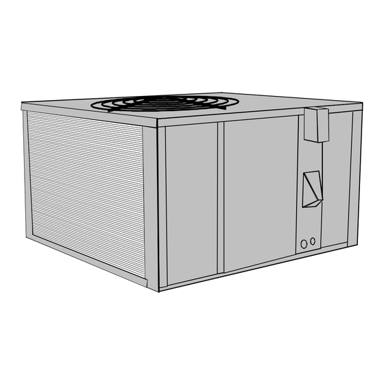
PGA**C, PGB**C and
PGD**C Single Package
Gas-Electric Heating
and Cooling Unit
Contents
ATTENTION INSTALLING PERSONNEL ............. 1
I. Safety Information ............................................ 2
II. General Information ......................................... 3
III. Rigging and Handling .................................... 3
IV. Gas Piping ....................................................... 4
V. Electrical Wiring ............................................... 7
Vl. Circulating Air and Filters .............................. 8
VII. Venting ........................................................... 9
VIII. Condensate Drain ......................................... 9
IX. Heating Sequence of Operations .................. 9
X. Cooling Sequence of Operations ................. 10
Xl. Startup and Adjustment ............................... 10
XII. Maintenance ................................................ 13
XIII. Accessories and Functional Parts ............ 15
Amana Forced Air Central Units Design Complies With Requirements Embod-
ied in The American National Standard / National Standard of Canada Shown
Below.
ANSI Z21.47•CAN/CGA-2.3 Central Furnaces
As a professional installer you have an obligation to
know the product better than the customer. This in-
cludes all safety precautions and related items.
Prior to actual installation, thoroughly familiarize your-
self with this Instruction Manual. Pay special attention
to all safety warnings. Often during installation or repair
it is possible to place yourself in a position which is
more hazardous than when the unit is in operation.
Remember, it is your responsibility to install the
January1998(1)
H eating
RECOGNIZE THIS SYMBOL AS A SAFETY PRECAUTION
ATTENTION INSTALLING PERSONNEL
Fayetteville, TN 37334
®
A ir C onditioning
Installation Instructions
Affix this manual, Specification Sheet and User Informa-
tion manual adjacent to the unit.
product safely and to know it well enough to be able to
instruct a customer in its safe use.
Safety is a matter of common sense...a matter of
thinking before acting. Most dealers have a list of
specific good safety practices...follow them.
The precautions listed in this Installation Manual should
not supersede existing practices but should be consid-
ered as supplemental information.
Amana
10692406
Advertisement
Table of Contents

Related Manuals for Amana PGA**C


Summary of Contents for Amana PGA**C
-
Page 1: Table Of Contents
Xl. Startup and Adjustment ....... 10 XII. Maintenance ..........13 XIII. Accessories and Functional Parts .... 15 Amana Forced Air Central Units Design Complies With Requirements Embod- ied in The American National Standard / National Standard of Canada Shown Below. -
Page 2: Safety Information
It is important to complete the owner registration card and chemical(s) which may cause death or mail it immediately. This will assist Amana in contacting you serious illness and which are known by the if any service or warranty information should change in the State of California to cause cancer, birth future. -
Page 3: General Information
• Allow clearances from the enclosure as shown in Speci- of the area to be conditioned. The loads should be calcu- fication Sheet for fire protection, proper operation, and lated by an approved method or in accordance with service access. These clearances must be perma- A.S.H.R.A.E. -
Page 4: Gas Piping
Refer to the Roof Curb Installation Instructions for proper The minimum supply pressure should not vary from that curb installation. Curbing must be installed in compliance shown in the table above because this could prevent the unit with the National Roofing Contractors Association Manual. from having dependable ignition. - Page 5 Refer to Figure 2 for the general layout at the unit. The CHECKING THE GAS PIPING following rules apply: CAUTION 1. Use black iron or steel pipe and fittings for the building To prevent personal injury or property piping. damage due to fire, the following 2.
- Page 6 TANKS AND PIPING FOR PROPANE GAS INSTALLATIONS WARNING To prevent death, personal injury or property damage due to fire or explosion caused by a propane gas leak, install a gas detecting warning device. Since rust can reduce the level of odorant in propane gas, a gas detecting warning device is the only reliable way to detect a propane gas leak.
-
Page 7: Electrical Wiring
Refer to the unit wiring diagram for electrical connections. V. Electrical Wiring When installed, the unit must be electrically grounded in accordance with local codes or in the absence of local LOCATING THE THERMOSTAT codes, with the National Electrical Code, ANSI/NFPA No. Thermostat should be mounted 5 feet above the floor, on a 70, and/or the CSA C22.1 Electrical Code, if an external vibration free inside wall in a room or a hallway that has good... -
Page 8: Vl. Circulating Air And Filters
From Unit Figure 6 Typical Thermostat and Unit 24 V Wiring Hookup Electrical Power Directly To Junction Box Vl. Circulating Air and Filters AIRFLOW CONVERSION Units can easily be converted from horizontal to vertical airflow delivery. Units will ship from the factory ready for horizontal airflow. If conversion to vertical airflow is necessary, proceed as follows: NOTE: Refer to Specification Sheet shipped with the unit or... -
Page 9: Venting
All ductwork exposed to the outdoors must include a weath- To install the flue hood cover: erproof barrier and adequate insulation. 1. Remove the flue hood and bug screen from inside the heating compartment. A duct system should be installed in accordance with Stan- dards of the National Board of Fire Underwriters for the 2. -
Page 10: Cooling Sequence Of Operations
8. The gas valve and combustion blower will be de- WARNING energized when the thermostat opens. To prevent death, personal injury or property 9. There is an adjustable Heat Fan OFF of approximately damage due to fire or explosion, before 60/90/120/150 second delay (factory set at 120). - Page 11 OPERATING INSTRUCTIONS (HEATING) GAS INPUT AND PRESSURES NOTE: Figure 2 illustrates the proper gas valve mounting Gas supply pressure and manifold pressure with the burn- location. ers operating must be as specified on the rating plate. GAS PRESSURE CHECKS Gas inlet pressure must be checked and adjusted in accor- dance to the type of fuel being consumed.
- Page 12 2. The temperature rise must be within the range specified To adjust the pressure regulator, remove the adjustment on the rating plate. screw or cover on the gas valve. Turn out (counterclock- wise) to decrease pressure, turn in (clockwise) to increase NOTE: Air temperature rise is the temperature difference pressure.
-
Page 13: Maintenance
2. Circulating Air Blower will continue to run for 60, 90, 120 XII. Maintenance or 150 seconds, depending on the setting. NOTE: If necessary, adjust fan OFF delay settings to obtain WARNING satisfactory comfort level. To avoid death or personal injury due to electrical shock, disconnect electrical CAUTION power before performing any maintenance. - Page 14 NOTE: After cleaning, the microamp signal should be in the range listed in Specification Sheet. Flame Sensor Ignitor Burner Check the burner flames for: Assembly 1. Good adjustment 2. Stable, soft and blue 3. Not curling, floating, or lifting off. Pilot Figure 17 Tube...
-
Page 15: Accessories And Functional Parts
XIII. Accessories and Functional Parts SHEET METAL ACCESSORIES Additional Amana accessories, as described in Table 4, can be purchased to fit specific application needs. Accessories can be ordered by the part numbers in the table and each accessory includes its own separate instructions.
Need help?
Do you have a question about the PGA**C and is the answer not in the manual?
Questions and answers