Amana PGB**C Installation Instructions Manual
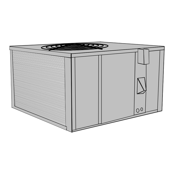
Single package gas-electric heating and cooling unit
Hide thumbs
Also See for PGB**C:
- Service instructions manual (85 pages) ,
- Installation instructions manual (15 pages)
Table of Contents
Advertisement
PGB**C and PGD**C
Single Package
Gas-Electric
Heating and Cooling Unit
Attention Installing Personnel ............................. 1
I. Safety Information .............................................. 2
II. General Information .......................................... 3
III. Rigging and Handling ...................................... 4
IV. Gas Piping ........................................................ 5
V. Electrical Wiring ................................................ 8
Vl. Circulating Air and Filters ............................. 10
VII. Venting ........................................................... 11
VIII. Condensate Drain ........................................ 11
IX. Heating Sequence of Operations ................. 12
X. Cooling Sequence of Operations .................. 12
Xl. Startup and Adjustment ................................ 12
XII. Maintenance .................................................. 16
XIII. Accessories and Functional Parts ............. 18
Amana Forced Air Central Units Design Complies With Requirements Em-
bodied in The American National Standard / National Standard of Canada
Shown Below.
ANSI Z21.47•CAN/CGA-2.3 Central Furnaces
As a professional installer you have an obligation to
know the product better than the customer. This
includes all safety precautions and related items.
Prior to actual installation, thoroughly familiarize your-
self with this Instruction Manual. Pay special atten-
tion to all safety warnings. Often during installation or
repair it is possible to place yourself in a position
which is more hazardous than when the unit is in
operation.
Effective: May 1995
Contents
RECOGNIZE THIS SYMBOL AS A SAFETY PRECAUTION
ATTENTION INSTALLING PERSONNEL
Amana Refrigeration, Inc.
Fayetteville, TN 37334
Installation Instructions
Affix this manual, Specification Sheet and User
Information manual adjacent to the unit.
Remember, it is your responsibility to install the
product safely and to know it well enough to be able
to instruct a customer in its safe use.
Safety is a matter of common sense...a matter of
thinking before acting. Most dealers have a list of
specific good safety practices...follow them.
The precautions listed in this Installation Manual
should not supersede existing practices but should
be considered as supplemental information.
10692403
Advertisement
Table of Contents

Related Manuals for Amana PGB**C


Summary of Contents for Amana PGB**C
-
Page 1: Table Of Contents
Xl. Startup and Adjustment ........ 12 XII. Maintenance ..........16 XIII. Accessories and Functional Parts ..... 18 Amana Forced Air Central Units Design Complies With Requirements Em- bodied in The American National Standard / National Standard of Canada Shown Below. -
Page 2: Safety Information
It is important to complete the owner registration card any phone in building. and mail it immediately. This will assist Amana in con- • Immediately call gas supplier from a neighbor’s tacting you if any service or warranty information should phone. -
Page 3: General Information
NOT locate outside air intake device installed on combustible flooring or class A, B, or C (economizer, manual fresh air intake, motorized roofing material, then the Amana roof curb (PRC01*) fresh air intake) too close to an exhaust outlet, gas is required. -
Page 4: Rigging And Handling
All units are securely packed in shipping containers ductwork should be attached to the curb prior to install- approved by the International Safe Transit Association. ing the unit. Ductwork dimensions are shown in Amana The carton should be checked upon arrival for external roof curb installation instructions. -
Page 5: Gas Piping
Piping IV. Gas Piping IMPORTANT NOTE: To avoid possible unsatisfactory operation or equipment damage due to under firing of IMPORTANT NOTE: This unit is factory set to operate equipment, do not undersize the natural/propane gas on natural gas at the altitudes shown on the rating plate. piping from the meter/tank to the unit. - Page 6 8. The unit must be connected to the building piping • This unit and its shut-off valve must be by one of the following methods: disconnected from the gas supply dur- • Rigid metallic pipe and fittings ing any pressure testing of that system •...
- Page 7 For satisfactory operation, propane gas pressure must be 10 inch W.C. at the unit manifold with all gas appli- ances in operation. Maintaining proper gas pressure depends on three main factors: 1. Vaporization rate, which depends on (a) tempera- ture of the liquid, and (b) wetted surface area of the container or containers.
-
Page 8: Electrical Wiring
Refer to the unit wiring diagram for electrical connec- V. Electrical Wiring tions. When installed, the unit must be electrically grounded in accordance with local codes or in the ab- Locating The Thermostat sence of local codes, with the National Electrical Code, Thermostat should be mounted 5 feet above the floor, ANSI/NFPA No. - Page 9 Unit Voltage The unit transformer is factory connected for 230V op- eration. If the unit is to operate on 208V, reconnect the transformer primary lead and induced draft blower mo- tor leads as shown on the unit wiring diagram. Heat Anticipator Setting The heat anticipator in the room thermostat must be correctly adjusted to obtain the proper number of heat- ing cycles per hour and to prevent the room tempera-...
-
Page 10: Vl. Circulating Air And Filters
Ductwork dimen- • Cut insulation around bottom openings and remove sions are shown in the Amana PRC roof curb installa- panels from the bottom of the unit, saving the screws tion manual. -
Page 11: Venting
3. Insofar as is practical, close all building doors and VII. Venting windows and all doors between the space in which the appliances remaining connected to the com- Flue Hood And Air Inlet Hood Installation mon venting system are located and other spaces Install the flue hood and air inlet hood prior to operation of the building. -
Page 12: Heating Sequence Of Operations
IX. Heating Sequence of Operations Xl. Startup and Adjustment Normal Sequence of Operation - Heating Heating Startup 1. Thermostat calls for heat. The combustion blower is General Information immediately energized. This unit is equipped with an electronic ignition device 2. The pressure switch contacts transfer. to light the pilot which then lights the burners. - Page 13 6. Turn the gas control valve knob to the OFF position. Secondary Limit Control Do not force. (Figure 11) On the PGB**C & PGD**C series, a second limit control is placed on the blower scroll. This control will open due 7. Wait five minutes to clear out any gas.
- Page 14 Check The Manifold Pressure Check Main Burner Flame A tapped opening is provided in the gas valve to facili- Flames should be stable, soft and blue (dust may cause tate measurement of the manifold pressure. A “U” Tube orange tips but they must not be yellow) and extending manometer having a scale range from 0 to 12 inches of directly outward from the burner without curling, floating water should be used for this measurement.
- Page 15 MOTOR NEUTRAL XFMR LEADS Compressor Protection Devices The PGB**C and PGD**C compressor includes compo- nents which are designed to protect the compressor CIR BLOWER against abnormal operating conditions. WARNING Figure 13 To avoid death or personal injury, al-...
-
Page 16: Maintenance
Condenser, Evaporator, and Induced Draft XII. Maintenance Motors Bearings on the air circulating blower motor, condenser WARNING motor and the combustion fan motor are permanently To avoid death or personal injury due to lubricated. No additional oiling is required. electrical shock, disconnect electrical Flame Sensor (Qualified Servicer Only) power before performing any mainte- A drop in the flame sensing signal can be caused by a... - Page 17 Cleaning Flue Passages (Qualified Servicer Only) WARNING 1. Shut off electric power and gas supply to the unit. To avoid death or personal injury due to 2. Remove burner assembly by disconnecting the gas electrical shock, do not remove any in- line and removing the manifold brackets from the ternal compartment covers or attempt partition panel.
-
Page 18: Accessories And Functional Parts
Sheet Metal Accessories order. Additional Amana accessories, as described in Table 4, can be purchased to fit specific application needs. Ac- 2. Although only functional parts are shown in Figure cessories can be ordered by the part numbers in the 16, all sheet metal parts, doors, etc.
Need help?
Do you have a question about the PGB**C and is the answer not in the manual?
Questions and answers