Table of Contents
Advertisement
N
N
N
4
B
a
n
d
V
D
S
L
4
B
a
n
d
V
D
S
L
4
B
a
n
d
V
D
S
L
U
S
U
S
U
S
V
F
-
2
0
0
L
S
/
R
V
F
-
2
0
0
L
S
/
R
V
F
-
2
0
0
L
S
/
R
C
O
/
C
P
E
B
r
i
d
C
O
/
C
P
E
B
r
i
d
C
O
/
C
P
E
B
r
i
d
E
R
'
S
M
A
E
R
'
S
M
A
E
R
'
S
M
A
v
e
r
.
S
v
e
r
.
S
v
e
r
.
S
g
e
w
i
t
h
D
i
p
S
g
e
w
i
t
h
D
i
p
S
g
e
w
i
t
h
D
i
p
S
N
U
A
L
N
U
A
L
N
U
A
L
w
i
t
c
h
w
i
t
c
h
w
i
t
c
h
Advertisement
Table of Contents

Related Manuals for netsys NVF-200LS/R


Summary of Contents for netsys NVF-200LS/R
- Page 1 ’ ’ ’...
-
Page 2: Copyright
In the interest of improving internal design, operational function, and/or reliability, NETSYS reserves the right to make changes to the products described in this document without notice. NETSYS does not assume any liability that may occur due to the use or application of the product(s) or circuit layout(s) described herein. -
Page 3: Foreword: Vdsl Point To Point Solution
IP DSLAM over auto speed or fix speed function. Therefore, NVF-200LS/R ver.S supports plug & play operations on the subscriber-site and can do auto and manual selection of the data speed. An ideal solution for delivering cost-effective, high-performance broadband/multimedia services to Multi-Dwelling Units... - Page 4 NVF-200LS/R ver.S 4 Band VDSL CO/CPE Bridge USER’S MANUAL Ver. B.4 Caution: The NVF-200 is for indoor applications only. This product does not have waterproof protection. We do not recommend for harsh environments. If user insist to install it for industrial applications (-20° C ~ 70° C (-4° F ~ 158° F)), please do not use the included commercial-grade power supply.
-
Page 5: Safety Warnings
NVF-200LS/R ver.S 4 Band VDSL CO/CPE Bridge USER’S MANUAL Ver. B.4 Safety Warnings For your safety, be sure to read and follow all warning notices and instructions before using the device. DO NOT open the device or unit. Opening or removing covers can expose you to dangerous high voltage points or other risks. -
Page 6: Table Of Contents
NVF-200LS/R ver.S 4 Band VDSL CO/CPE Bridge USER’S MANUAL Ver. B.4 Table of Contents COPYRIGHT ................................ 1 FOREWORD: VDSL POINT TO POINT SOLUTION..................... 2 SAFETY WARNINGS ............................4 CHAPTER 1. UNPACKING INFORMATION......................7 1.1 Check List ......................................7 CHAPTER 2. INSTALLING THE BRIDGE......................8 2.1 Hardware Installation..................................8... - Page 7 NVF-200LS/R ver.S 4 Band VDSL CO/CPE Bridge USER’S MANUAL Ver. B.4 3.1 Front Panel....................................12 3.2 Front Indicators ....................................13 3.3 Rear Panel....................................14 3.4 Side Panel....................................15 CHAPTER 4. FIRMWARE DESCRIPTION ......................17 APPENDIX A: CABLE REQUIREMENTS ......................18 APPENDIX B: PRODUCT SPECIFICATION ....................... 21 APPENDIX C: 4 BAND VDSL ELECTRICAL CHARACTERISTICS ..............
-
Page 8: Chapter 1. Unpacking Information
1. Do not use sub-standard power supply. Before connecting the power supply to the device, be sure to check compliance with specifications. The NVF-200LS/R ver.S of the power supply use DC 5-12V/1A. 2. Power supply included in package is commercial-grade. Do not use in harsh environments. -
Page 9: Chapter 2. Installing The Bridge
NVF-200LS/R ver.S 4 Band VDSL CO/CPE Bridge USER’S MANUAL Ver. B.4 Chapter 2. Installing the Bridge 2.1 Hardware Installation This chapter describes how to install the bridge and establishes network connections and may install the bridge on any level surface (e.g. a table or shelf). However, please take note of the following minimum site requirements before one begin. -
Page 10: General Rules
NVF-200LS/R ver.S 4 Band VDSL CO/CPE Bridge USER’S MANUAL Ver. B.4 2.3 General Rules Before making any connections to the bridge, please note the following rules: • Ethernet Port (RJ-45) All network connections to the bridge Ethernet port must be made using Category 5 UTP for 100Mbps, Category 3, 4 UTP for 10Mbps. -
Page 11: Connecting The Rj-11 / Rj-45 Ports
NVF-200LS/R ver.S 4 Band VDSL CO/CPE Bridge USER’S MANUAL Ver. B.4 2.5 Connecting the RJ-11 / RJ-45 Ports 1. The bridge’s RJ-11 ports supports max distance 1.9km at 5M/5M or max rate 25M/25M symmetrical and distances up to 800m data service across existing phone wiring, without interfering with standard voice transmissions, easy-to-use which do not require installation of additional wiring. - Page 12 NVF-200LS/R ver.S 4 Band VDSL CO/CPE Bridge USER’S MANUAL Ver. B.4 2. NVF-200LS/R bridge has an embedded splitter between every VDSL side (Line) and POTS (Phone) side. It permits one to deliver broadband service on the same lines as Plain Old Telephone Service (POTS), PBX, ISDN traffic and VDSL Signal.
-
Page 13: Chapter 3. Hardware Description
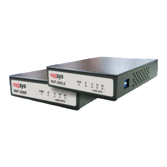
NVF-200LS/R ver.S 4 Band VDSL CO/CPE Bridge USER’S MANUAL Ver. B.4 Chapter 3. Hardware Description This section describes the important parts of the bridge. It features the front panel, side panel and rear connectors. NVF-200LS/R ver.S Outward 3.1 Front Panel The figure shows the front panel. -
Page 14: Front Indicators
NVF-200LS/R ver.S 4 Band VDSL CO/CPE Bridge USER’S MANUAL Ver. B.4 3.2 Front Indicators The bridge has Five LED indicators. The following Table shows the description. (Table 3-1) Table 3-1 LED Indicators Description and Operation Color Status Descriptions The device is receiving the power and functioning properly. -
Page 15: Rear Panel
NVF-200LS/R ver.S 4 Band VDSL CO/CPE Bridge USER’S MANUAL Ver. B.4 3.3 Rear Panel The following figure shows the rear connectors. (Figure 3.2) Figure 3.2 Rear connectors And the table shows the description. (Table 3-2) Table 3-2 Description of the bridge rear connectors... -
Page 16: Side Panel
NVF-200LS/R ver.S 4 Band VDSL CO/CPE Bridge USER’S MANUAL Ver. B.4 3.4 Side Panel The following figure shows the DIP switch connection. (Figure 3.3) Figure 3.3 Side panel At quick glance, it is easy to see that the DIP switch pin 1 is switch ON where it is in auto-speed and that is also the default mode. - Page 17 NVF-200LS/R ver.S 4 Band VDSL CO/CPE Bridge USER’S MANUAL Ver. B.4 To set the data speed to 25Mbps simply switch ON the pin 2 while the other pins are switch OFF. To change it to 15Mbps, switch ON the pin 3 while the other pins are switch OFF, for 5Mbps switch on the pin 4 while other are switch OFF.
-
Page 18: Chapter 4. Firmware Description
Auto and manual data speed selector description: NVF-200LS/R is a 4band VDSL solution which supports real plug & play and can do auto and manual selection of the data speed, the setting of the data speed depends on the phone cable length limit, they can support 5M/15M/25M symmetrical data service but depends on installation environment. -
Page 19: Appendix A: Cable Requirements
NVF-200LS/R ver.S 4 Band VDSL CO/CPE Bridge USER’S MANUAL Ver. B.4 Appendix A: Cable Requirements A.1 Ethernet Cable A CAT 3, 4 or 5 UTP (unshielded twisted pair) cable is typically used to connect the Ethernet device to the modem. A 10Base-T cable often consists of four pairs of wires, two of which are used for transmission. - Page 20 NVF-200LS/R ver.S 4 Band VDSL CO/CPE Bridge USER’S MANUAL Ver. B.4 Figure A-2 Pin Assignments and Wiring for an RJ-45 Straight-Through Cable Figure A-3 Pin Assignments and Wiring for an RJ-45 Crossover Cable...
- Page 21 NVF-200LS/R ver.S 4 Band VDSL CO/CPE Bridge USER’S MANUAL Ver. B.4 A.2 Telephone wire Standard telephone wire of any gauge or type-flat, twisted or quad is used to connect the Modem to the telephone network. A telephone cable typically consists of three pairs of wires, one of which is used for transmission. The connector at the end of the telephone cable is called an RJ-11 connector and it consists of six pins.
-
Page 22: Appendix B: Product Specification
NVF-200LS/R ver.S 4 Band VDSL CO/CPE Bridge USER’S MANUAL Ver. B.4 Appendix B: Product Specification Key Features & Benefits • Max speed at 5M/5M with distance up to 1.9km(6333ft), Max speed at 15M/15M with distance up to 1.3km(4333ft), Max speed at 25M/25M with distance up to 800m(2666ft) •... - Page 23 NVF-200LS/R ver.S 4 Band VDSL CO/CPE Bridge USER’S MANUAL Ver. B.4 Product Specification IEEE802.3 standard Standard: IEEE802.3u standard Compliant with ETSI, ITU & ANSI standards 1 * RJ-45 10/100Mbps Ethernet port 1 * RJ-11 connector for EoVDSL Interface: 1 * RJ-11 connector for telephone connection...
-
Page 24: Appendix C: 4 Band Vdsl Electrical Characteristics
NVF-200LS/R ver.S 4 Band VDSL CO/CPE Bridge USER’S MANUAL Ver. B.4 Appendix C: 4 Band VDSL Electrical Characteristics Parameter Min. Typ. Max. Unit Transmit Spectrum Receive Transmit -61.5 dBm/Hz PSD Level Receive dBm/Hz Noise Margin Transmit 5Mbps Link Margin Receive... -
Page 25: Appendix D: Troubleshooting
NVF-200LS/R ver.S 4 Band VDSL CO/CPE Bridge USER’S MANUAL Ver. B.4 Appendix D: Troubleshooting Diagnosing the Bridge’s Indicators The bridge can be easily monitored through its comprehensive panel indicators. These indicators assist the network manager in identifying problems the hub may encounter. This section describes common problems you may encounter and possible solutions. - Page 26 NVF-200LS/R ver.S 4 Band VDSL CO/CPE Bridge USER’S MANUAL Ver. B.4 VDSL Link cannot be established. 3. Symptom: VDSL speed mode setting failure or phone cable length is over the specification limit of the speed Cause: mode. 3.1 Please make sure that the phone wire must be connected between NVF-200LS and NVF-200R ver.S when both are power on.
- Page 27 NVF-200LS/R ver.S 4 Band VDSL CO/CPE Bridge USER’S MANUAL Ver. B.4 You must connect according to the following chart if you want to connect CO and CPE with NTBA. Solution: 6. Symptom: VDSL line is at link margin. Cause: When the VDSL line is linking between 2 speeds at 5/15Mbps or 15/25Mbps.
- Page 28 NVF-200LS/R ver.S 4 Band VDSL CO/CPE Bridge USER’S MANUAL Ver. B.4 System Diagnostics Power and Cooling Problems If the POWER indicator does not turn on when the power cord is plugged in, you may have a problem with the power outlet, power cord, or internal power supply as explained in the previous section.
- Page 29 NVF-200LS/R ver.S 4 Band VDSL CO/CPE Bridge USER’S MANUAL Ver. B.4 Physical Configuration If problems occur after altering the network configuration, restore the original connections, and try to track the problem down by implementing the new changes, one step at a time. Ensure that cable distances and other physical aspects of the installation do not exceed recommendations.
-
Page 30: Appendix E: Compliance And Safety Information
NVF-200LS/R ver.S 4 Band VDSL CO/CPE Bridge USER’S MANUAL Ver. B.4 Appendix E: Compliance and Safety Information FCC Radio Frequency Interference Statement This equipment has been tested and found to comply with the limits for a computing device, pursuant to Part 15 of FCC rules. - Page 31 NVF-200LS/R ver.S 4 Band VDSL CO/CPE Bridge USER’S MANUAL Ver. B.4 proper functioning of your equipment. If they do, you will be notified in advance in order for you to make necessary modifications to maintain uninterrupted service. This equipment may not be used on coin service provided by the telephone company. Connection to party lines is subject to state tariffs.
- Page 32 NVF-200LS/R ver.S 4 Band VDSL CO/CPE Bridge USER’S MANUAL Ver. B.4 FCC Warning This equipment has been tested to comply with the limits for a Class B digital device, pursuant to Part 15 of the FCC Rules. These limits are designed to provide reasonable protection against harmful interference when the equipment is operated in a commercial environment.
-
Page 33: Warranty
NVF-200LS/R ver.S 4 Band VDSL CO/CPE Bridge USER’S MANUAL Ver. B.4 Warranty The original owner that the product delivered in this package will be free from defects in material and workmanship for one year parts after purchase. There will be a minimal charge to replace consumable components, such as fuses, power transformers, and mechanical cooling devices. -
Page 34: Chinese Sj/T 11364-2006
NVF-200LS/R ver.S 4 Band VDSL CO/CPE Bridge USER’S MANUAL Ver. B.4 Chinese SJ/T 11364-2006 有 毒 有 害 物 质 或 元 素 部件名称 铅(Pb) 汞(Hg) 镉(Cd) 六价铬[Cr(VI)] 多溴联苯(PBB) 多溴二苯醚(PBDE) 结构壳体 ○ ○ ○ ○ ○ ○ 电路组 ○ ○...
Need help?
Do you have a question about the NVF-200LS/R and is the answer not in the manual?
Questions and answers