Table of Contents

Related Manuals for netsys NV-202


Summary of Contents for netsys NV-202
- Page 1 ’ ’ ’...
-
Page 2: Copyright
In the interest of improving internal design, operational function, and/or reliability, NETSYS reserves the right to make changes to the products described in this document without notice. NETSYS does not assume any liability that may occur due to the use or application of the product(s) or circuit layout(s) described herein. -
Page 3: Foreword: Vdsl2 Solution
Since VDSL2 has the characteristic of higher bandwidth over shorter distances, the ideal architecture for Telecoms is to use fiber optic lines as the backbone and a VDSL2 line as the last mile into the home or office. With outstanding throughput, the NV-202 can complement a fiber network to offer the best solution for delivering Triple play(Video/Voice/Data) or home entertainment services. -
Page 4: Safety Warnings
NV-202 VDSL2 Bridge with DIP Switch USER’S MANUAL Ver. A4 Safety Warnings For your safety, be sure to read and follow all warning notices and instructions before using the device. DO NOT open the device or unit. Opening or removing the cover may expose you to dangerous high voltage points or other risks. -
Page 5: Table Of Contents
NV-202 VDSL2 Bridge with DIP Switch USER’S MANUAL Ver. A4 TABLE OF CONTENTS COPYRIGHT ................................ 1 FOREWORD: VDSL2 SOLUTION ........................2 SAFETY WARNINGS ............................3 CHAPTER 1. UNPACKING INFORMATION ......................6 1.1 Check List ......................................6 CHAPTER 2. INSTALLING THE BRIDGE......................7 2.1 Hardware Installation..................................7... - Page 6 NV-202 VDSL2 Bridge with DIP Switch USER’S MANUAL Ver. A4 CHAPTER 3. HARDWARE DESCRIPTION ......................13 3.1 Front Panel....................................14 3.2 Front Indicators ....................................15 3.3 Rear Panel ....................................16 APPENDIX A: CABLE REQUIREMENTS ......................22 APPENDIX B: PRODUCT SPECIFICATION ....................... 24 APPENDIX C: DIN-RAIL MOUNT INSTALLATION....................26 APPENDIX D: TROUBLESHOOTING ........................
-
Page 7: Chapter 1. Unpacking Information
NV-202 VDSL2 Bridge with DIP Switch USER’S MANUAL Ver. A4 CHAPTER 1. UNPACKING INFORMATION 1.1 Check List Carefully unpack the package and check its contents against the checklist. Package Contents: 1 x NV-202 1 x QR code for user’s Accessory: manual hyperlink. -
Page 8: Chapter 2. Installing The Bridge
2.1 Hardware Installation This chapter describes how to install the bridge and establish the network connections. The NV-202 may be installed on any level surface (e.g. a table or shelf or rail). However, please take note of the following minimum site requirements before one begin. -
Page 9: General Rules
NV-202 VDSL2 Bridge with DIP Switch USER’S MANUAL Ver. A4 2.3 General Rules Before making any connections to the bridge, please note the following rules: • Ethernet Port (RJ-45) All network connections to the bridge Ethernet port must be made using Category 5 UTP/STP or above for 100Mbps, Category 3, 4 UTP for 10Mbps. -
Page 10: Connecting The Bridge
NV-202 VDSL2 Bridge with DIP Switch USER’S MANUAL Ver. A4 • External Splitter Our devices support both ISDN interfaces U(2w) and S/T(4w). When using an external splitter, make sure that you are using one that is compatible with the interface you want to use. -
Page 11: Connecting The Rj-11 / Rj-45 Ports
2.5 Connecting the RJ-11 / RJ-45 Ports The line port has 2 connectors: RJ-45 and terminal block. It is used to connect with NV-202(CO) using a single pair phone cable to NV-202(CPE) bridge side (point to point solution). Take note that NV-202 line port RJ-11 and terminal block cannot be used at the same time. - Page 12 Use 24 ~ 26 gauge twisted pair phone wiring, we do not recommend 28 gauge or above. Be sure the phone cable has been installed before NV-202 is powered on.
-
Page 13: Vdsl2 Bridge Application
NV-202 VDSL2 Bridge with DIP Switch USER’S MANUAL Ver. A4 2.6 VDSL2 bridge Application The bridge’s line port supports 100Mbps for data service across existing phone wiring. It is easy-to-use which do not requires installation of additional wiring. Every modular phone jack in the home can become a port on the LAN. Networking devices can be... -
Page 14: Chapter 3. Hardware Description
NV-202 VDSL2 Bridge with DIP Switch USER’S MANUAL Ver. A4 Chapter 3. Hardware Description This section describes the important parts of the bridge. It features the front panel and rear panel. NV-202 Outward... -
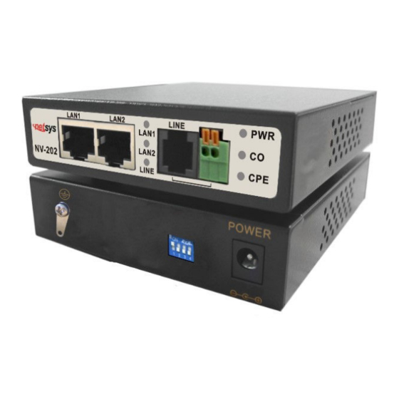
Page 15: Front Panel
NV-202 VDSL2 Bridge with DIP Switch USER’S MANUAL Ver. A4 3.1 Front Panel The front panel provides a simple interface monitoring of the bridged. (Figure 3.1) Figure 3.1 Front Panel Tip: At a quick glance of the front panel, it is easy to determine if it has Ethernet signal from its RJ-45 port and if there is vdsl line signal on RJ-11 port. -
Page 16: Front Indicators
Note: It is normal for the connection between two bridged to take up to 3 minutes, due to NV-202 to establish a link mechanism in auto-negotiation, that detects and calculates CO and CPE both PBO and PSD level, noise levels and other arguments for getting a... -
Page 17: Rear Panel
NV-202 VDSL2 Bridge with DIP Switch USER’S MANUAL Ver. A4 3.3 Rear Panel The following figure shows the rear panel. (Figure 3.2) Figure 3.2 Rear Panel And the table shows the description. (Table 3-3) Table 3-3 Description of the bridge front connectors... - Page 18 CO/CPE Mode Band SNRM Interleave / INP CO Mode High Band 8ms / INP=2 CPE Mode Low band 1ms / INP=0 Note: 1. The DIP switch default values are OFF. 2. Please power off NV-202, before making any transmission mode configuration.
- Page 19 ON: High Band Mode (500KHz to 30MHz), and enable VDSL2 spectrum is 500KHz to 30MHz. It can pass through ISDN spectrum(0 ~ 499KHz are empty). OFF: Low Band Mode (300KHz to 30MHz), the NV-202 will auto-detect the cable length and auto choice speed mode. PIN3:...
- Page 20 NV-202 VDSL2 Bridge with DIP Switch USER’S MANUAL Ver. A4 TIP(Reference Only): Interleave delay function is used in digital data transmission technology to protect the transmission against noise issue and data error. If during transit more than a certain amount of data has been lost then the data cannot be correctly decoded. Short bursts of noise on the line can cause these data packets to become corrupt and the bridge has to re-request data which in turn can slow down the overall rate at which data is transmitted.
- Page 21 2. Please note that the user can use 12VDC power input. Do not exceed DC 12V. Be sure to disconnect the power before installing and/or wiring your NV-202 bridge. Please calculate the maximum possible current in each power wire and common wire. Observe all electrical codes dictating the maximum current allowable for each wire size.
- Page 22 NV-202 VDSL2 Bridge with DIP Switch USER’S MANUAL Ver. A4 Grounding the NV-202 NV-202 is designed to enhance EMS performance by grounding. NV-202 comes with for grounding the switches. For optimal EMS performance, connection of the left side of the NV-202 rear panel ground lug to the grounding point.
-
Page 23: Appendix A: Cable Requirements
NV-202 VDSL2 Bridge with DIP Switch USER’S MANUAL Ver. A4 Appendix A: Cable Requirements Ethernet Cable A CAT 3~7 UTP (unshielded twisted pair) cable is typically used to connect the Ethernet device to the bridge. A 10Base-T cable often consists of four pairs of wires, two of which are used for transmission. The connector at the end of the 10Base-T cable is referred to as an RJ-45 connector and it consists of eight pins. - Page 24 NV-202 VDSL2 Bridge with DIP Switch USER’S MANUAL Ver. A4 Figure A-2 Pin Assignments and Wiring for an RJ-45 Straight-Through Cable Figure A-3 Pin Assignments and Wiring for an RJ-45 Crossover Cable...
-
Page 25: Appendix B: Product Specification
NV-202 VDSL2 Bridge with DIP Switch USER’S MANUAL Ver. A4 Appendix B: Product Specification Key Features & Benefits • Supports RJ-11/Terminal Block combo for Line port. • Supports high bandwidth up to 100Mbps symmetric over Line ports • Support long reach mode up to 3 km with 24 gauge phone wire •... - Page 26 NV-202 VDSL2 Bridge with DIP Switch USER’S MANUAL Ver. A4 1 x DIP Switch 1 x Power Jack RJ-45 (Ethernet): Category 3~7 UTP/STP Cable Connections: RJ-11 (VDSL2): Twisted Pair phone wire 1 x Power LED 2 x Link/Active Status for Ethernet port...
-
Page 27: Appendix C: Din-Rail Mount Installation
NV-202 VDSL2 Bridge with DIP Switch USER’S MANUAL Ver. A4 Appendix C: DIN-Rail mount installation This appendix describes how to install the DIN-Rail to the bridged. The accessory is optional. Please refer to install the DIN-RAIL as following step: 1. Install the DIN-Rail mounting plate to the NV-202. -
Page 28: Appendix D: Troubleshooting
2.4 Check if the proper cable type is used and its length exceed specified limits. 2.5 Check the bridge on the attached device and cable connections for possible defects. 2.6 Make sure the phone wire must be connecting NV-202 first, when powered on. 2.7 Replace the defective bridge or cable if necessary. - Page 29 VDSL setting failure or phone cable length is over the specification limit. 3.1 Please make sure that the phone wire must be connected between NV-202(CO) and NV-202(CPE) when both are power on. NV-202(CO) will do link speed function depending on phone wire length, therefore if NV-202(CO) can’t detect NV-202(CPE) over phone wire while...
- Page 30 NV-202 VDSL2 Bridge with DIP Switch USER’S MANUAL Ver. A4 infrastructure. The protocol was standardized in the International Telecommunication Union telecommunications sector (ITU-T) as Recommendation G.993.2. It was announced as finalized on 27 May 2005,[1] and first published on 17 February 2006. Several corrections and amendments were published in 2007 through 2011.
- Page 31 NV-202 VDSL2 Bridge with DIP Switch USER’S MANUAL Ver. A4 5. Question: What is SNR(Signal-to-Noise) Signal-to-noise ratio (often abbreviated SNR or S/N) is a measure used in science and engineering that compares the level of a desired signal to the level of background noise. It is defined as the ratio of signal power to the noise power.
- Page 32 30a cannot establish link, it will auto change to profile 17a Solution: of long reach mode. In addition to, NV-202 point-to-point band plan will depending on with different distance to automatically configure different parameters.
- Page 33 NV-202 VDSL2 Bridge with DIP Switch USER’S MANUAL Ver. A4 System Diagnostics Power and Cooling Problems If the POWER indicator does not turn on when the power cord is plugged in, you may have a problem with the power outlet, power cord, or internal power supply. However, if the unit power is off after running for a while, check for loose power connections, power losses or surges at the power outlet.
- Page 34 NV-202 VDSL2 Bridge with DIP Switch USER’S MANUAL Ver. A4 down by implementing the new changes, one step at a time. Ensure that cable distances and other physical aspects of the installation do not exceed recommendations. System Integrity As a last resort verify the switch integrity with a power-on reset. Turn the power to the switch off and then on several...
-
Page 35: Appendix E: Compliance Information
NV-202 VDSL2 Bridge with DIP Switch USER’S MANUAL Ver. A4 Appendix E: Compliance Information FCC Radio Frequency Interference Statement This equipment has been tested and found to comply with the limits for a computing device, pursuant to Part 15 of FCC rules. - Page 36 NV-202 VDSL2 Bridge with DIP Switch USER’S MANUAL Ver. A4 proper functioning of your equipment. If they do, you will be notified in advance in order for you to make necessary modifications to maintain uninterrupted service. This equipment may not be used on coin service provided by the telephone company. Connection to party lines is subject to state tariffs.
- Page 37 NV-202 VDSL2 Bridge with DIP Switch USER’S MANUAL Ver. A4 WEEE Warning To avoid the potential effects on the environment and human health as a result of the presence of hazardous substances in electrical and electronic equipment, end users of electrical and electronic equipment should understand the meaning of the crossed-out wheeled bin symbol.
-
Page 38: Appendix F: Performance Table
NV-202 VDSL2 Bridge with DIP Switch USER’S MANUAL Ver. A4 Appendix F: Performance Table Test Environment: Test Items Descriptions VDSL2 Bridge CO Mode x 1 NV-202 CO Mode (Pin1 ON) VDSL2 Bridge CPE Mode x 1 NV-202 CPE Mode (Pin1 OFF) - Page 39 NV-202 VDSL2 Bridge with DIP Switch USER’S MANUAL Ver. A4 Spectrum: 300K~30MHz (US: Up Stream / DS: Down Stream) (Reference only) Cable Length Cable Length Cable Length US [Mbps] DS [Mbps] US [Mbps] DS [Mbps] US [Mbps] DS [Mbps] (meters)
-
Page 40: Warranty
NV-202 VDSL2 Bridge with DIP Switch USER’S MANUAL Ver. A4 Warranty The original product that the owner delivered in this package will be free from defects in material and workmanship for one year parts after purchase. There will be a minimal charge to replace consumable components, such as fuses, power transformers, and mechanical cooling devices. -
Page 41: Chinese Sj/T 11364-2006
NV-202 VDSL2 Bridge with DIP Switch USER’S MANUAL Ver. A4 Chinese SJ/T 11364-2006 有 毒 有 害 物 质 或 元 素 部件名称 铅(Pb) 汞(Hg) 镉(Cd) 六价铬[Cr(VI)] 多溴联苯(PBB) 多溴二苯醚(PBDE) 结构壳体 ○ ○ ○ ○ ○ ○ 电路组 ○ ○ ○...
Need help?
Do you have a question about the NV-202 and is the answer not in the manual?
Questions and answers