
Related Manuals for Sparkrite SR100


Summary of Contents for Sparkrite SR100
- Page 1 REMOTE CAR ALARM SR100 SYSTEM TECHNICAL HELP LINE - 01429 862616 email : technicalsupport@stadium.co.uk...
-
Page 2: Sr100 Features
Automatic reset. Gives continuous protection until alarm is disarmed by remote control. • Door locking control wire. Allows doors to be locked/unlocked by remote control when connected to optional SR911 Central Door Locking Interface. SR100 REMOTE CONTROL CAR ALARM SYSTEM... -
Page 3: Table Of Contents
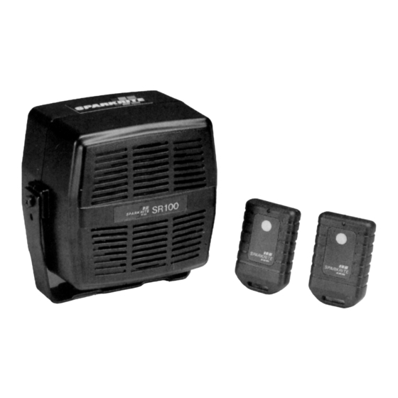
SPARKRITE SR100 REMOTE CONTROL CAR ALARM SYSTEM The Sparkrite SR100 compact remote control car alarm system incorporates the latest “state of the art” microprocessor technology offering the ultimate in product reliability and performance. The unique easy-fit design offers easy installation and ensures many years of trouble free operations. -
Page 4: Operating Your Sparkrite Sr100 Alarm System
The radio remote control transmitter conforms to DTI legislation with each unit allocated a unique security code. Additional remote controls are available on special order from Halfords or direct from Sparkrite using the enclosed order form, quoting the serial number on the back of the remote control. -
Page 5: Remote Panic
If you feel threatened outside of your vehicle and within range you can trigger your SR100 by holding the remote control button depressed for 3 seconds. This will commence an alarm cycle of 30 seconds and draw attention to your situation and the vehicle. -
Page 6: Valet Alarm Override Feature
If the valet switch is turned to the enable position without the ignition being turned on first, when the alarm is armed, the siren will sound after 30 seconds arm-up period. If this occurs, repeat the disable/enable sequence. SR100 REMOTE CONTROL CAR ALARM SYSTEM... -
Page 7: Fitting Instructions
FITTING INSTRUCTIONS IMPORTANT: • Your SR100 is suitable for 12V negative earth vehicles only. • Refer to Car Owners manual for the procedure for disconnection of your battery before commencing the installation of this Alarm. • The vehicle battery must be disconnected during the installation procedure except where it is necessary to carry out circuit testing specified. -
Page 8: Making Reliable Connections
Check behind any panels for hidden pipes or wiring before drilling holes. Secure the alarm to the bracket using the small bolts supplied making sure that front face of the alarm is kept vertical to ensure effective operation of the shock sensor. SR100 REMOTE CONTROL CAR ALARM SYSTEM... -
Page 9: Sr100 Wiring Connections
Do not fit the rubber boot to the alarm at this stage. You can now make connections to the car wiring as shown. All wires MUST be connected in the sequence outlined in these instructions. SR100 REMOTE CONTROL CAR ALARM SYSTEM... -
Page 10: Armed Indicator Led
LEFT hand indicator circuit. NOTE: The Alarm gives a 12 volt (+) positive output to flash the indicators. In the rare case where indicators are negatively (earth) switched, contact Sparkrite for assistance. SR100 REMOTE CONTROL CAR ALARM SYSTEM... -
Page 11: Green Wire-Alarm Antenna
If the electric fan still operates when the ignition is turned OFF then a connection from the SR100 must be made to prevent the current sensing function from triggering the alarm. The cooling fan wiring will be configured as shown in Fig. 4 or 5. -
Page 12: Blue Wire Door Switches
IDC connector. If the courtesy light remains on when the door switch is removed, contact Sparkrite for installation details specific to your car. IMPORTANT: The Passive Arming function will only work if the BLUE wire is connected as described above. -
Page 13: Pink Wire Ignition Input
Valet Key Switch is in the Enable position before attempting to connect the RED wire. The SR100 is triggered by the operation of the interior light or any electrical circuit on the vehicle. This is detected by the RED power supply wire. -
Page 14: Boot And Bonnet Switches
BOOT AND BONNET SWITCHES If your vehicle is not fitted with Boot/Bonnet switches which operate the interior light , these switches are available from Sparkrite as an accessory. The Switch Kit (Part No. SR910) should be installed and connected as shown in Fig. 6. -
Page 15: Testing The Alarm Installation
Finally ensure that all wiring is neatly secured/insulated where necessary and fuses etc. are checked for safety. Install the window warning labels on the drivers and passenger windows and make a note of your remote control serial number in the space provided on page 22. SR100 REMOTE CONTROL CAR ALARM SYSTEM... - Page 16 WARNING: Failure to carry out these instructions will result in water ingress, false alarms and will invalidate any warranty claim. Complete the instillation by neatly securing the ultrasonic unit and the alarm wiring harness. SR100 REMOTE CONTROL CAR ALARM SYSTEM...
-
Page 17: Trouble Shooting Guide
To replace the battery remove the screw from the near of the casing and carefully separate the transmitter moulding. Replace with 12 volt Sparkrite battery Part No. SR904 observing correct polarity. ARMING AND DISARMING Pressing button on remote control lights the transmitter indicator LED but alarm does not arm/disarm. - Page 18 Check the connections to the ORANGE and BROWN immobiliser wires. If none of the above solutions solve the problem either consult your dealer, or contact the Sparkrite Technical and After Sales Service (T.A.S.S.) on 01429 862616. ALARM GIVES FALSE ALARMS Check position of Valet Switch and Reset using Enable/Disable sequence.
-
Page 19: Additional Remote Control Transmitters
Halfords or contact the Sparkrite Technical and After Sales Service (T.A.S.S). PRODUCT APPROVALS Your SR100 has been tested and approved by various governmental bodies to comply with the latest European directives for E.M.C. and Low power transmission. Approvals: EMC European directive 95/54. -
Page 20: Accessories For The Sr100 Alarm
ACI door lock actuator used with SR911 used with SR911 if your vehicle central locking system can only be locked/unlocked from the drivers door SR915 professional style ultrasonic interior detector with discreet sensors. Issue 29 July 99 SR100 REMOTE CONTROL CAR ALARM SYSTEM...
Need help?
Do you have a question about the SR100 and is the answer not in the manual?
Questions and answers