
Related Manuals for Sparkrite SRA8


Summary of Contents for Sparkrite SRA8
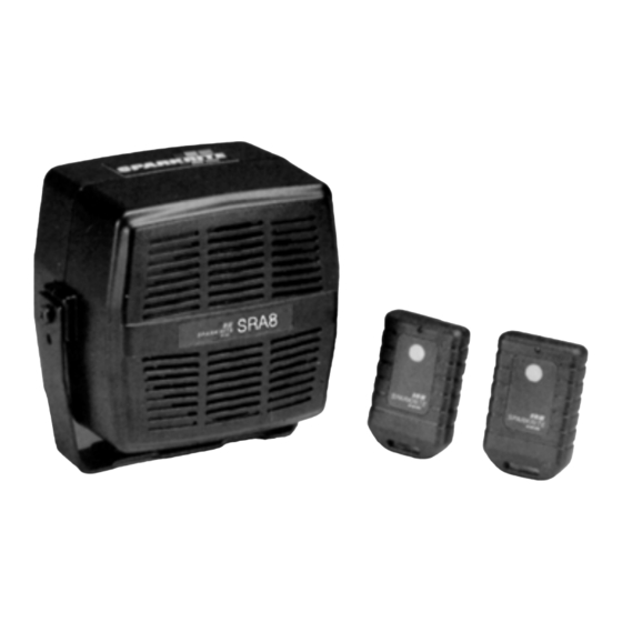
- Page 1 - 1 - REMOTE CAR ALARM SYSTEM Technical Help Line – 01429 862616 Email- technical.support@stadiumcp.co.uk...
-
Page 2: Sra8 Features
SRA8 FEATURES • 2 radio remote controlled transmitters. DTI approved. Instant arm/disarm. • Starter motor circuit immobilisation - disables starter motor when alarm is sounding. • Passive arming option - allows automatic arming on closure of last door. Disarm by remote control. -
Page 3: Table Of Contents
The Sparkrite SRA8 compact remote control car alarm system incorporates the latest “state of the art” microprocessor technology offering the ultimate in product reliability and performance. The unique easy-fit design offers easy installation and ensures many years of trouble free operations Table of Contents SRA8 Features………………………………………………………….. -
Page 4: Operating Your Sparkrite Sra8 Alarm System
The radio remote control transmitter conforms to DTI legislation with each unit allocated a unique security code. Additional remote controls are available on special order from Sparkrite using the enclosed order form, quoting the serial number on the back of the remote control. -
Page 5: Disarming Your Alarm
DISARMING YOUR ALARM To Disarm the Alarm • Press the remote control transmitter button once, the indicators will flash twice and the siren will chirp twice. • If you trigger the alarm accidentally, follow the normal disarming procedure keep the remote control button depressed until the alarm stops. ENTRY ALERT If when disarming the alarm the siren gives 3 chirps and 3 flashes of the indicators this indicates that the alarm has been triggered in your absence. -
Page 6: Passive Arming/Current Sensing Disable
PASSIVE ARMING/CURRENT SENSING DISABLE PASSIVE ARMING Passive arming is a feature whereby the alarm will automatically “arm” a short time after the last door on the vehicle has been closed. Disarming the alarm is achieved by pressing the remote control button or by turning on the vehicle ignition. -
Page 7: Valet Alarm Override Feature
VALET/SERVICE OVERRIDE FEATURE This feature disables the alarm. It is useful if you are taking your car to a garage for servicing, particulary if the “Passive Arming” feature is selected. Turn ON the vehicle ignition. Turn the Valet Switch on the alarm, clockwise 90 degrees to the disable position and remove the key. -
Page 8: Fitting Instructions
FITTING INSTRUCTIONS IMPORTANT: • Your SRA8 is suitable for 12V negative earth vehicles only. • Refer to Car Owners manual for the procedure for disconnection of your battery before commencing the installation of this Alarm. • The vehicle battery must be disconnected during the installation procedure except where it is necessary to carry out circuit testing specified. -
Page 9: Making Reliable Connections
MAKING RELIABLE CONNECTIONS All connections in the engine bay area must be made by using either solder-joints or good quality crimp termination’s. The use of Insulation Displacement Connectors (I.D.C.’s) such as Warning: scotch locks is not recommended in the engine bay area. The use of IDCs in this area may result in the alarm failing to operate correctly or cause false alarms. -
Page 10: Mounting The Main Alarm Module & Harness Location
MOUNTING THE MAIN ALARM MODULE Locate a mounting position for the alarm in the vehicle engine compartment close to the front of the vehicle and in a position where it is difficult to again access to the alarm wiring from below the car. Ensure that the alarm is located away from extreme heat, areas subject to water and at least 12”... -
Page 11: Wiring Connections
SRA8 WIRING CONNECTIONS... -
Page 12: Armed Indicator Led
ARMED INDICATOR LED Please note this is an optional fitment, providing an additional visible deterrent to car thieves. The alarm will still function correctly if you choose not to install the LED. To install follow the instructions below. • Decide on a suitable location to mount the LED. We would suggest using one of the blanking plugs found on most modern cars, or the plastic casing surrounding the ignition barrel or steering column. -
Page 13: Green Wire-Alarm Antenna
RED wire of the alarm. If the electric fan still operates when the ignition is turned OFF then a connection from the SRA8 must be made to prevent the current sensing function from triggering the alarm. The cooling fan wiring will be configured as shown in Fig. -
Page 14: Blue Wire Door Switches
Fig 5 Fig 4 BLUE WIRE-DOOR SWITCH NOTE: To ensure correct operation of your alarm, the BLUE wire must be connected prior to connecting BLACK earth wire or RED main alarm supply wire. Most four door cars operate the courtesy light from all four doors so connecting the alarm to one door switch will connect all of the doors. -
Page 15: Black Wire-Earth
IDC connector. If the courtesy light remains on when the door switch is removed, contact Sparkrite for installation details specific to your car. IMPORTANT: The Passive Arming function will only work if the BLUE wire is connected as described above... -
Page 16: Pink Wire Ignition Input
PINK-IGNITION INPUT Using a test lamp, locate a 12 volt wire on the ignition switch, which is live ONLY in the STARTING and RUN positions of the ignition key. This is normally the wire that becomes live when the ignition key is turned from position 1 to position 2. -
Page 17: Red Wire-Power Supply Current Sensing
Enable position before attempting to connect the RED wire. The SRA8 is triggered by the operation of the interior light or any electrical circuit on the vehicle. This is detected by the RED power supply wire. The trigger sensitivity will vary from vehicle to vehicle depending on size and age of the car battery and the rating of the interior light bulb. -
Page 18: Boot And Bonnet Switches
BOOT AND BONNET SWITCHES If your vehicle is not fitted with Boot/Bonnet switches which operate the interior light , these switches are available from Sparkrite as an accessory. The Switch Kit (Part No. SR910) should be installed and connected as shown in Fig. -
Page 19: Shock Sensor
SHOCK SENSOR The SRA8 includes an electronic shock sensing device to detect sudden impact or shock which is transmitted through the body- work of the vehicle. Fig 7 The sensitivity adjuster is located on the rear of the main alarm unit. -
Page 20: Testing The Alarm Installation
TESTING THE ALARM INSTALLATION Check all connections are secure and the vehicle battery is connected. Ensure the car ignition is turned off. Press the remote control button. The alarm will disarm with one chirp and one flash of the indicators.Press the remote control button. The alarm will disarm with two chirps and two flashes of the indicators. -
Page 21: Ultrasonic Detector Unit
ULTRASONIC DETECTOR FEATURES • 40Khz Quartz crystal controlled electronics. • Professional style independent ultrasonic sensors with unique adjustment feature for maximum operating efficiency. • Underdash mounting electronics. • Fully adjustable sensitivity control. OPERATION When the alarm is armed, the ultrasonic unit is automatically activated and fills the inside of the vehicle invisible sound waves, setting up a steady pattern. - Page 22 Route each wire from the sensors neatly down the wind-screen pillars and under the dashboard. Ultrasonic Control Unit IMPORTANT The ultrasonic detector must only be connected to the alarm after removal of the fuse from the red 12V supply wire. Reconnect the fuse once the detector has been installed.
- Page 23 vehicle illuminates the RED LED. • If the triggers, disarm and rearm the alarm until the adjustment is complete. Do not set the sensitivity too high as this may result in false triggering. • Ensure, when leaving your vehicle, inertia seat belts are fully retracted and all windows and sunroof are closed.
-
Page 24: Trouble Shooting Guide
around the wires ensuring ample coverage. Once the silicone is in place a tie wrap (supplied) should be fastened around the narrow section of the rubber boot. The tie wrap will force part of the silicone back out of the rubber boot, this excess should NOT be wiped/cleaned away, but worked back into the boot. -
Page 25: Battery Replacement
To replace the battery remove the screw from the near of the casing and carefully separate the transmitter moulding. Replace with 12 volt Sparkrite battery Part No. SR904 observing correct polarity. ARMING AND DISARMING Pressing button on remote control lights the transmitter indicator LED but alarm does not arm/disarm. - Page 26 CAR WILL NOT START Check the connections to the ORANGE and BROWN immobiliser wires. If none of the above solutions solve the problem either consult your dealer, or contact the Sparkrite Technical and After Sales Service (T.A.S.S.) on 01429 862616...
- Page 27 ALARM GIVES FALSE ALARMS Check position of Valet Switch and Reset using Enable/Disable sequence. Bad Earth of Supply Connection. Check connection of BLACK earth wire. Check connection of RED supply wire. Post Ignition. Check that your vehicle does not have any electrical circuit operating when the vehicle is parked, i.e.
-
Page 28: Additional Remote Control Transmitters
REMOTE CONTROL SERIAL NO.___________________ TECHNICAL HELP If you have any problems with the installation of this alarm and the problem cannot be solved by consulting the troubleshooting section the this manual, contact the Sparkrite Technical and After Sales Service (T.A.S.S). -
Page 29: Accessories For The Sra8 Alarm
PRODUCT APPROVALS Your SRA8 alarm has been tested and approved by various governmental bodies to comply with the latest European directives for E.M.C. and Low power transmission. Approvals: EMC European directive 95/54. Approval No: ell 020041 RA/DTI Low power transmission.
Need help?
Do you have a question about the SRA8 and is the answer not in the manual?
Questions and answers