Table of Contents
Advertisement
Quick Links
Advertisement
Table of Contents

Related Manuals for Sparkrite SR90


Summary of Contents for Sparkrite SR90
- Page 1 REMOTE CONTROL CAR ALARM SYSTEM Email: technicalsupport@stadiumcp.co.uk...
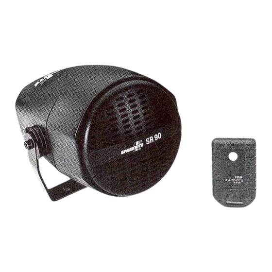
- Page 2 SPARKRITE SR90 REMOTE CAR ALARM SYSTEM INTRODUCTION The Sparkrite SR90 advanced remote control alarm system incorporates the latest "state-of-the-art" microprocessor technology offering the ultimate in product reliability and performance. Features: • Radio remote control-DTI approved. Instant arming and disarming. • Remote control panic feature-gives personal protection sounding siren for up to 50 seconds.
-
Page 3: Remote Panic
REMOTE PANIC If the transmitter button is pressed and held for three seconds, the SR90 will trigger and commence an alarm cycle as a possible means of summoning help, a very useful defense in case of attack or assault. -
Page 4: Feature Selection
When the SR90 is installed, it is recommended that the slide switch is set in the ON position. If your vehicle is fitted with an electrically operated, pulsed... -
Page 5: Fitting Instructions
FITTING INSTRUCTIONS Suitable for 12V negative earth vehicles only. IMPORTANT: The vehicle battery must be disconnected during the installation procedure, except where necessary to carry out circuit tests specified. TESTING PROCEDURE If you are unable to easily identify the correct wire on the vehicle to make a connection, it is recommended a 12 DC test lamp or test screwdriver is used. -
Page 6: Harness Location
When the alarm is armed, the red LED will illuminate. Following the 20 second exit delay, the LED will flash at 1 second intervals to indicate the SR90 is fully armed. If the alarm is triggered and completes a full alarm cycle (50 seconds), the LED will flash at half second intervals to indicate that a violation has occurred. -
Page 7: Wiring Diagram
WIRING DIAGRAM WIRING CONNECTIONS GREEN - RADIO AERIAL The GREEN aerial wire must not be cut or connected to anything metal, otherwise the operating range will be affected. Tape the antenna to the main harness to achieve optimum performance. VIOLET AND GREY-INDICATOR LIGHTS VIOLET Using the vehicle's wiring diagram or 12V test lamp, locate the wire on the indicator switch or direct on any indicator lamp, which illuminates the test bulb when the RIGHT hand indicator flashes on... - Page 8 YELLOW - ELECTRIC FAN INHIBIT If the cooling fan is switched by the ignition or no electric fan is fitted, insulate the YELLOW wire and leave disconnected. If your vehicle is fitted with a thermostatically controlled cooling fan which operates with the ignition switched off, the YELLOW lead must be connected to prevent false triggering of the alarm.
- Page 9 BOOT AND BONNET SWITCHES (OPTIONAL) (ii) To protect the boot and bonnet, it will be necessary to install additional pin switches (Sparkrite SR910) connected to the BLUE wire as shown in Fig 3. IMPORTANT: PASSIVE ARMING. THE BLUE WIRE MUST BE CONNECTED TO ANY COURTESY LIGHT...
-
Page 10: Red Wire - Power Supply/Current Sensing
Connecting further away e.g. the fusebox, will increase sensitivity. SENSOR INPUT The SR90 sensor input is located on the rear of the main alarm control module. This enables direct connection of Sparkrite accessories SR901 Ultrasonic Interior Detector or SR902 Interior Space Sensor to further protect your vehicle. -
Page 11: Troubleshooting Guide
TROUBLESHOOTING GUIDE REMOTE CONTROL TRANSMITTER Pressing button on remote control doesn't light transmitter indicator, next to button. • Battery inserted wrongly. • Poor battery connection. Adjust terminals to ensure good battery contact. • Discharged or missing battery. Replace battery. ARMING AND DISARMING Pressing button on remote control lights transmitter indicator, but has no effect on receiver indicator. -
Page 12: Additional Transmitters
If none of the above solutions solve the problem, either consult your dealer, or contact the Sparkrite Technical and After Sales Service (T.A.S.S.) on 01429 862616 ACCESSORIES FOR THE SR9O ALARM...
Need help?
Do you have a question about the SR90 and is the answer not in the manual?
Questions and answers