
Related Manuals for Sparkrite SR85


Summary of Contents for Sparkrite SR85
- Page 1 REMOTE CONTROL CAR ALARM SR85 SYSTEM Technical Help Line - 01429 862616 Email technicalsupport@stadium.co.uk...
- Page 2 • Door locking control wire. Allows doors to be locked/unlocked by remote control when connected to SR911 Central Door Locking Interface. • Sensor connection. Quick fit plug allows connection of ultrasonic detector units. SR85 REMOTE CONTROL CAR ALARM SYSTEM...
-
Page 3: Table Of Contents
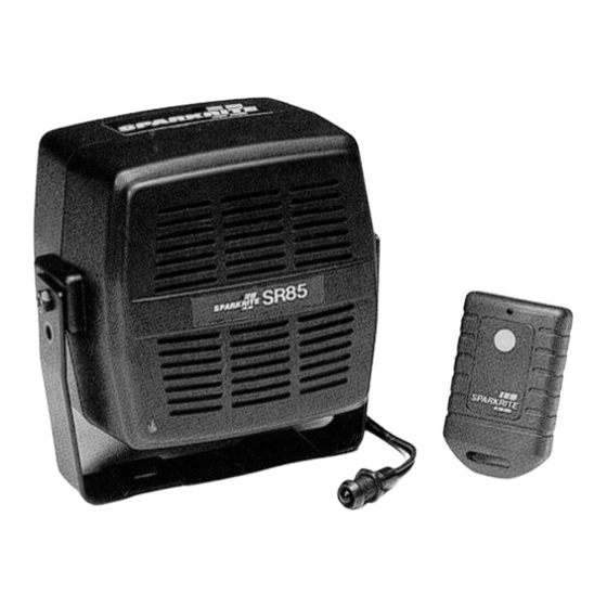
SPARKRITE SR85 REMOTE CONTROL CAR ALARM SYSTEM The Sparkrite SR85 compact remote control car alarm system incorporates the latest “state of the art” microprocessor technology offering the ultimate in product reliability and performance. The unique easy-fit design offers easy installation and ensures many years of trouble free operation. -
Page 4: Operating Your Sr85 Alarm System
The radio remote control transmitter conforms to DTI legislation with each unit allocated a unique security code. Additional remote controls are available on special order from your nearest stockist or direct from Sparkrite using the enclosed order form, quoting your serial number located on the back of the remote control. -
Page 5: Fitting Instructions
FITTING INSTRUCTIONS IMPORTANT: • Your SR85 is suitable for 12V negative earth vehicles only. • Refer to Car Owners manual for the procedure for disconnection of your battery before commencing the installation of this alarm. • The vehicle battery must be disconnected during the installation procedure except where it is necessary to carry out circuit testing specified. -
Page 6: Mounting The Main Alarm Module And Harness Location
Secure the alarm to the bracket using the small bolts supplied making sure that front face of the alarm is kept vertical (facing the front of the vehicle) to ensure effective operation of the shock sensor. SR85 REMOTE CONTROL CAR ALARM SYSTEM... -
Page 7: Sr85 Wiring Connections
You can now make connections to the car wiring as shown ALL the wires must be connected in the order outlined in these instructions. SR85 WIRING CONNECTIONS SR85 REMOTE CONTROL CAR ALARM SYSTEM... -
Page 8: Armed Indicator Led And Purple And Grey Wires-Indicators
Extend the GREEN wire and secure to the outside of the wiring harness to achieve optimum performance. Ensure the wire cannot come into contact with a hot surface, bare metal or immersed in water. SR85 REMOTE CONTROL CAR ALARM SYSTEM... -
Page 9: Yellow Wire-Electric Fan Inhibit
If the electric cooling fan still operates when the ignition is turned OFF then a connection from the SR85 must be made to prevent the current sensing function from false triggering the alarm. The cooling fan wiring will be configured as shown in Fig. 4 or 5. -
Page 10: Blue Wire-Door Switches And0 Black Wire-Earth
IDC connector. If the courtesy light remains on when the door switch is removed, contact Sparkrite for installation details specific to your car. BLACK WIRE-EARTH The BLACK wire must be connected to a good clean metal earthing point on the body work of the vehicle. -
Page 11: Red Wire-Power Supply Current Sensing
The BLUE alarm wire must be connected before attempting to connect the RED alarm wire. The SR85 is triggered by the operation of the interior light or any electrical circuit on the vehicle. This is detected by the RED power supply wire. -
Page 12: Boot And Bonnet Switches
BOOT AND BONNET SWITCHES If your vehicle is not fitted with Boot/Bonnet switches which operate the interior light these switches are available from Sparkrite as an accessory kit. The Switch Kit (Part No. SR910) should be installed and connected as shown in Fig. 6. Ensure the fixing screw for the... -
Page 13: Testing The Alarm Installation
Test remote panic features by holding down the remote control button for 3 seconds. The alarm will trigger. Release button and press again to disarm the alarm. If problems are encountered, refer to the trouble shooting guide before proceeding further. SR85 REMOTE CONTROL CAR ALARM SYSTEM... - Page 14 Complete the installation by neatly securing the ultrasonic unit and the alarm wiring harness using tie wraps and/or insulation tape. WARNING: Failure to carry out these instructions will result in water ingress, false alarms and will invalidate any warranty claim. SR85 REMOTE CONTROL CAR ALARM SYSTEM...
-
Page 15: Trouble Shooting Guide
To replace the battery remove the screw from the near of the casing and carefully separate the transmitter moulding. Replace with 12 volt Sparkrite battery Part No. SR904 observing correct polarity. ARMING AND DISARMING Pressing button on remote control lights the transmitter indicator LED but alarm does not arm/disarm. - Page 16 ADDITIONAL REMOTE CONTROL TRANSMITTERS Available from HALFORDS or Stadium Consumer Products at the following address: STADIUM CONSUMER PRODUCTS STADIUM NORTH UNITS 8-11 TOFTS FARM INDUSTRIAL ESTATE BRENDA ROAD HARTLEPOOL CLEVELAND TS25 2DH TELEPHONE: 01429 862616 SR85 REMOTE CONTROL CAR ALARM SYSTEM...
-
Page 17: Additional Remote Control Transmitters
Sparkrite Technical and After Sales Service (T.A.S.S) on 01429 862616. PRODUCT APPROVALS Your SR85 has been tested, and approved by various government bodies to comply with the latest European directives for E.M.C. and Low power transmission. APPROVALS:...
Need help?
Do you have a question about the SR85 and is the answer not in the manual?
Questions and answers