Table of Contents
Advertisement
MAY BE INSTALLED IN A SOLID FUEL BURNING FIREPLACE, AS A ZERO
CLEARANCE FIREPLACE OR WITH AN OPTIONAL
WARNING: If the information in this manual is not followed exactly, a fire or
explosion may result causing property damage, personal injury or loss of life.
Do not store or use gasoline or other flammable vapors and liquids in vicinity of this or any
other appliance.
WHAT TO DO IF YOU SMELL GAS:
Do not try to light any appliance.
Do not touch any electrical switch; do not use any phone in your building.
Immediately call your gas supplier from a neighbor's phone. Follow gas supplier's instruc-
tions.
If you cannot reach your gas supplier, call fire department.
Installation and service must be performed by a qualified installer, service agency or gas
supplier.
This is an unvented gas-fired heater. It uses air (oxygen) from room in which it is installed.
Provisions for adequate combustion and ventilation air must be provided. Refer to section "
Producing Adequate Air For Combustion And Ventilation" page 35.
This appliance may be installed in an aftermarket, permanently located, manufactured (mobile)
home, where not prohibited by local codes.
This appliance is only for use with type of gas indicated on rating plate. This appliance is not
convertible for use with other gases.
INSTALLER: Leave this manual with appliance.
CONSUMER: Retain this manual for future reference.
MANUFACTURED BY:
NEW BUCK CORPORATION
200 ETHAN ALLEN DRIVE
PO BOX 69
SPRUCE PINE, N.C. 28777
www.buckstove.com
MODEL 34
This appliance is intended for supplemental heating.
SURROUND.
Revised October 2010
Advertisement
Table of Contents

Related Manuals for New Buck Corporation 34


Summary of Contents for New Buck Corporation 34
- Page 1 MODEL 34 MAY BE INSTALLED IN A SOLID FUEL BURNING FIREPLACE, AS A ZERO SURROUND. CLEARANCE FIREPLACE OR WITH AN OPTIONAL WARNING: If the information in this manual is not followed exactly, a fire or explosion may result causing property damage, personal injury or loss of life.
-
Page 3: Table Of Contents
SECTION IV: Wooden Surround Installation (WS) ..............28 SECTION V: Zero Clearance (ZC)....................30 SECTION VI: Installation-After Market Mobile Home .............. 34 SECTION VII: Producing Adequate Air For Combustion And Ventilation ....... 35 Air For Combustion And Ventilation Inside Building ..............37 Air For Combustion And Ventilation Outdoors ................ -
Page 5: Section I: Safety Information
SECTION I SAFETY INFORMATION WARNINGS IMPORTANT: READ THIS OWNER’S MANUAL CAREFULLY AND COMPLETELY BEFORE TRYING TO ASSEMBLE, OPERATE, OR SERVICE APPLIANCE. IMPROPER USE OF THESE LOGS CAN CAUSE SERIOUS INJURY OR DEATH FROM BURNS, FIRE, EXPLOSION AND CARBON MONOXIDE POISONING. NOTE: When burning any unit or appliance that combusts fuel for heat, such as ... - Page 6 5. If this heater is used with propane gas, do not place propane supply tank(s) inside any structure. 6. What To Do IF You Smell Gas: Shut off gas supply. - Do not try to light any appliance. - Do not touch any electrical switch; do not use any phone in your building. - Immediately call your gas supplier from a neighbor’s phone.
- Page 7 21. All heater screens must be kept closed when operating gas logs. 22. “WARNING: Failure to keep primary air opening (s) of the burner (s) clean may result in soot and property damage.” 23. Do not use this heater for burning trash or cooking. Never place matches, paper, garbage or any other material on top of logs or into the flames.
-
Page 8: Section Ii: Fireplace Preparation/Solid Fuel Burning Fireplace (Fp)
SECTION II FIREPLACE PREPARATION The fireplace needs to be prepared before installing heater. A. Turn off the gas supply to fireplace. “WARNING: BEFORE INSTALLING IN A SOLID-FUEL BURNING FIREPLACE, CHIMNEY FLUE AND FIREBOX MUST BE CLEANED OF SOOT, CREOSOTE, ASHES AND LOOSE PAINT BY A QUALIFIED CHIMNEY CLEANER.”... -
Page 9: Fireplace Clearances(Fp)
INSTALLATION AND CLEARANCES To ensure a safe installation into a masonry or factory built fireplace, following instructions must be carefully followed: (1) Sidewall Clearances: Clearance from side of fireplace opening to any adjacent combustible wall should not be less than: right side 7", left side 7". (2) Ceiling Clearances: The ceiling height should not be less than 24"... -
Page 10: Placement Of Logs
CR3329 CERAMIC LOG SET PLACEMENT, FOR MODEL 34 (1-R) (1-L) WARNING: Failure to position parts in accordance with these diagrams or failure to use only parts specifically approved with this heater may result in property damage or personal injury. WARNING: POSITIONING OF LOGS IS VERY CRITICAL (SEE DIAGRAM ABOVE). - Page 11 E.S.B. LOG SET PLACEMENT FOR MODEL 34 “MILLIVOLT ONLY” WARNING: Failure to position parts in accordance with these diagrams or failure to use only parts specifically approved with this heater may result in property damage or personal injury. WARNING: POSITIONING OF LOGS IS VERY CRITICAL (SEE DIAGRAM ABOVE).
-
Page 12: Gas Pressure Check
GAS PRESSURE CHECK Check inlet pressure to burner to ensure that it is as shown in table below. NOTE:The pressure check point is located on the right side of valve facing burner, for SIT Millivolt, and left side for SIT Modulating. Appliance and its appliance main gas valve must be disconnected from the gas supply piping system during any pressure testing of that system at test pressures in excess of 1/2 psi (3.5kPa). -
Page 13: Lighting Instructions - Itt Millivolt Valve
LIGHTING INSTRUCTIONS MILLIVOLT VALVE (ITT) FOR YOUR SAFETY, READ BEFORE LIGHTING WARNING IF YOU DO NOT FOLLOW THESE INSTRUCTIONS EXACTLY, A FIRE OR EXPLOSION MAY RESULT CAUSING PROPERTY DAMAGE, PERSONAL INJURY OR LOSS OF LIFE. A. This appliance has a pilot which must be lit by hand. When lighting pilot, follow these instructions exactly. - Page 14 LIGHTING INSTRUCTIONS 1. STOP! Read the safety information on previous page. 2. Make sure tmanual shutoff valve is fully closed. If equipped with thermostat, set to lowest setting. 3. Turn off all electrical power to appliance. 4. Open access panel door located at bottom front of appliance. 5.
- Page 15 If the pilot will not stay lit after several tries, turn gas control knob to “OFF” and call your service technician or gas supplier. IGNITOR ELECTRODE PILOT BURNER THERMO-PILE THERMO-COUPLE 12. Turn control knob counterclockwise to “ON” position. Push “ON/OFF” toggle switch to “ON”...
-
Page 16: Manual Lighting Procedure
THERMOSTAT CONTROL OPERATION This valve operates off of millivolts produced by the generator. You may choose to use an optional wall thermostat or remote control. If so, see page 22 for wiring diagram. MANUAL LIGHTING PROCEDURE 1. If pilot cannot be lit with piezo, it can be manually lit with the use of a paper match and a lighter rod. -
Page 17: Lighting Instructions - Sit Modulating Valve Or- Manual (Sit)
LIGHTING INSTRUCTIONS MODULATING VALVE (SIT) MANUAL VALVE (SIT) FOR YOUR SAFETY READ BEFORE LIGHTING WARNING IF YOU DO NOT FOLLOW THESE INSTRUCTIONS EXACTLY, A FIRE OR EXPLOSION MAY RESULT CAUSING PROPERTY DAMAGE, PERSONAL INJURY OR LOSS OF LIFE. A. This appliance has a pilot which must be lit by hand. When lighting pilot, follow these instructions exactly. - Page 18 LIGHTING INSTRUCTIONS 1. STOP! Read the safety information on previous page. 2. Make sure manual shutoff valve is fully closed. 3. Turn off all electrical power to appliance. 4. Open access panel door located at bottom front of appliance. 5. Turn control knob clockwise to full “OFF”...
-
Page 19: To Turn Off Gas To Appliance
11. Turn gas control knob counterclockwise to “ON” position. Continue to turn gas control knob counterclockwise to your desired setting. 12. Close access panel door. 13. Turn on all electrical power to appliance. CAUTION DO NOT TRY TO ADJUST HEATING LEVELS BY USING MANUAL SHUTOFF VALVE. TO TURN OFF GAS TO APPLIANCE SHUTTING OFF UNIT 1. - Page 20 THERMOSTAT CONTROL OPERATION 1. Thermostat control on this heater differs from standard thermostats. Standard thermostats simply turn burner on and off. The thermostat used on this heater senses room temperature and adjusts amount of gas flow to burner. This will increase or decrease flame height. At times, room may exceed set temperature, which will cause burner to shut off.
-
Page 21: Lighting Instructions - Sit Millivolt Valve
OPERATING INSTRUCTIONS Before operating this appliance, proceed through following checklist. 1. Read and understand these instructions before operating this appliance. 2. Check that there are no gas leaks. If you smell gas do not attempt to light this appliance. 3. Verify that log placement is correct. WARNING: ANY CHANGE TO THIS HEATER OR ITS CONTROLS CAN BE DANGEROUS. - Page 22 LIGHTING INSTRUCTIONS 1. STOP! Read the safety information on reverse side of this label (page 19). 2. Make sure manual shutoff valve is fully closed. If equipped with thermostat, set to lowest setting. 3. Turn off all electrical power to appliance. 4.
- Page 23 11. Turn control knob counterclockwise to “ON”. 12. If using unit without wall thermostat place Auto/Off/Manual switch to manual position. If using wall thermostat place Auto/Off /Manual switch to auto position and place thermostat to a setting higher than room temperature. 13.
- Page 24 MANUAL LIGHTING PROCEDURE 1. If pilot cannot be lit with piezo, it can be manually lit with the use of a paper match and a lighter rod. 2. Open access panel door located at bottom front of appliance. 3. Place match in holder and light. With left hand, turn control knob counterclockwise to “PILOT”position.
-
Page 25: Flame Check
FLAME CHECK A periodic check of the flames should be made. The pilot flame should always be present when gas logs are in operation. See Figure 4. Rear Flames: The flames at rear or at either side of top log should be very similar, yellow in color, and should be about 3"... -
Page 26: Wiring Diagram
WIRING DIAGRAM THERMOSTAT JUMPER MOTOR JUMPER JUMPER WHITE GREEN BLACK RHEOSTAT BLACK POWER CORD Figure 5 WARNING: CHILDREN AND ADULTS SHOULD BE ALERTED TO HAZARDS OF HIGH SURFACE TEMPERATURES AND SHOULD STAY AWAY TO AVOID BURNS OR CLOTHING IGNITION. YOUNG CHILDREN SHOULD BE CAREFULLY SUPERVISED WHEN THEY ARE IN SAME ROOM WITH APPLIANCE WARNING:... - Page 27 GROUNDED THREE-PRONG RECEPTACLE. NOTE: #PESBRO84 Blower may be used with Model FP-42-ZC. Rating: 120 volts/60HZ/1.1 Amps. See Figure 17, page 34 for wiring diagram. NOTE: For convenience, allow licensed electrician to install properly grounded 3-plug receptacle near unit. ROOM BLOWER INSTALLATION AND OPERATION INSTRUCTIONS Room air blower is located at rear of unit in bottom chamber.
-
Page 28: Section Iii: Solid Fuel Burning Fireplace Installation (Fp)
INSTALLATION MODEL 34 (FP) IN SOLID FUEL BURNING FIREPLACES (1) Model FP-34 may be installed in a masonry fireplace. The minimum fireplace dimension must be 24" high, 29-1/2" wide, and 12" deep. (2) For minimum dimensions for the sidewall and mantel, see Figure 6. - Page 29 Set top (long) trim panel in place on top of unit. Panel should be flat against outside face of fireplace and standing vertically. Mark along lower edge of trim panel with a pencil to make reference line for mounting. NOTE: If used in installation trim panels or surrounds shall not seal ventilation openings in fireplace.
-
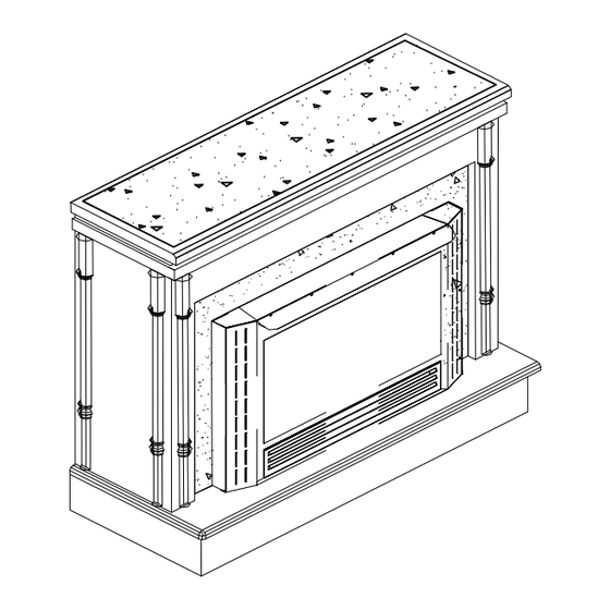
Page 30: Section Iv: Wooden Surround Installation (Ws)
SECTION IV INSTALLATION OF MODEL 34 (WS) OPTIONAL WOODEN SURROUND (KIT#PAKDFP34) NOTE: See page 26, figure 6 for clearances. (1) When choosing right location for your heater and surround (mantel) keep the following in mind: NOTE: Due to high temperatures, this heater should be located out of traffic areas and away from furniture and draperies. - Page 31 STEP10: Place top on to surround (mantel), flush with back and equal on each end. Secure both ends and middle with screws. EXPLODED VIEW OF MODEL 34 SURROUND KIT# PAKDFP34 AS VIEWED FROM BACK OF SURROUND (MANTEL) SURROUND BASE...
-
Page 32: Section V: Zero Clearance (Zc)
SECTION V MODEL 34 (ZC) ZERO CLEARANCE INSTALLATION The installation must conform with local codes or in the absence of local codes, with National Fuel Gas Code, ANSI Z223.1/NFPA54. This appliance may be installed in an After-Market Manufactured (Mobile) Home, where not prohibited by state or local codes. - Page 33 GAS LINE 3-1/4" 4-1/4" WARNING: Installation and repairs should be performed by a qualified service person. The appliance should be inspected before use and at least annually by a professional service person. More frequent cleaning may be required due to excessive lint from carpeting, bedding material, etc.
- Page 34 FIREPLACE CLEARANCES (ZC) COMBUSTIBLE MATERIALS MUST Fireplace may be placed directly on a combustible INSTALLED OVER OR TOUCH ANY BLACK floor, against a combustible wall at marked PAINTED SURFACE. DO NOT BLOCK HEAT clearances or on a raised wooden platform. CIRCULATING AIR OUTLETS.
- Page 35 FINISHING YOUR FIREPLACE (ZC) There is a wide variety of finishing material coverings such as paneling or wall-board may available for your fireplace from formal wall not overlap black face of fireplace. Space treatments with marble and mantels, to rustic between wall covering and fireplace should wood paneling,...
-
Page 36: Section Vi: Installation-After Market Mobile Home
THIS APPLIANCE IS ONLY FOR USE WITH THE TYPE OF GAS INDICATED ON RATING PLATE. THIS APPLIANCE IS NOT CONVERTIBLE FOR USE WITH OTHER GASES. NOTE: For mobile home installation follow “Installation”, pages 6-33. NOTE: See “Producing Adequate Air For Combustion And Ventilation” page 35 Page 34... -
Page 37: Section Vii: Producing Adequate Air For Combustion And Ventilation
PRODUCING ADEQUATE AIR FOR COMBUSTION AND VENTILATION This section is for residential or manufactured (mobile) installation “This heater shall not be installed in a confined space or unusually tight construction unless provisions are adequate combustion and ventilation air.” NOTE: This heater shall not be installed in a room or space unless the required volume of indoor combustion air is provided by the method in National Fuel Gas Code, ANSIZ223.1/NFPA 54, the International Fuel Gas Code, or applicable codes. - Page 38 1. Determine the volume of the space (length x width x height). Length x Width x Height = cu.ft.(volume of space) EXAMPLE: 20 ft.(Length) x 16 ft.(Width) x 8 ft.(ceiling Height)= 2560 cu. ft. (volume of space) If additional ventilation to adjoining room is supplied with grills or openings, add the volume of these rooms to the total volume of the space.
-
Page 39: Air For Combustion And Ventilation Inside Building
AIR FOR COMBUSTION AND VENTILATION INSIDE BUILDING This fresh air would come from an adjoining unconfined space. When venting to an adjoining space, you must provide two permanent openings: one within 12" of ceiling and one within 12" of floor, on wall connecting two spaces. (See Options 1 and 2, Figure 8.) You can also remove door into adjoining room. -
Page 40: Air For Combustion And Ventilation Outdoors
WARNING THIS APPLIANCE MUST HAVE FRESH AIR FOR PROPER OPERATION. IF NOT, POOR FUEL COMBUSTION COULD RESULT. READ FOLLOWING INSTRUCTIONS TO ENSURE PROPER FRESH AIR FOR THIS AND OTHER FUEL- BURNING APPLIANCES IN YOUR HOME. AIR FOR COMBUSTION AND VENTILATION OUTDOORS Provide extra fresh air by using ventilation grills or ducts. -
Page 41: Important Safeguards
IMPORTANT SAFEGUARDS Although your gas logs are very realistic in appearance, it is not a real burning fireplace and must not be used for burning rejected material. To avoid irreparable damage to heater or personal injury, matches, paper, garbage or any other material must not be placed or thrown on top of logs or into flames. -
Page 42: Troubleshooting
TROUBLESHOOTING WARNING TURN OFF, UNPLUG HEATER AND LET COOL BEFORE SERVICING. ONLY A QUALIFIED SERVICE PERSON SHOULD SERVICE AND REPAIR HEATER. CAUTION NEVER USE A WIRE, NEEDLE OR SIMILAR OBJECT TO CLEAN ODS/PILOT. THIS CAN DAMAGE ODS/PILOT. OBSERVED POSSIBLE PROBLEM CAUSE SOLUTION Igniter button is pressed... - Page 43 OBSERVED POSSIBLE PROBLEM CAUSE SOLUTION Igniter button is pressed Air in gas lines when installed Continue to hold down Spark at ODS/Pilot control knob. Repeat igniting No Ignition (continued) operation until air is removed. Depleted gas supply Contact local propane gas company ODS/Pilot is clogged Clean ODS/Pilot or replace...
- Page 44 OBSERVED POSSIBLE PROBLEM CAUSE SOLUTION Burner does not light after Burner orifice is clogged Clean burner (see Cleaning ODS/Pilot is lit and Maintenance) or replace burner orifice Inlet gas pressure is too low Contact local propane gas company Delayed ignition of burner Manifold pressure is too low Contact local propane gas company...
- Page 45 WARNING IF YOU SMELL GAS: * SHUT OFF GAS SUPPLY * DO NOT TRY TO LIGHT APPLIANCE * DO NOT TOUCH ANY ELECTRICAL SWITCH; DO NOT USE ANY PHONE IN YOUR BUILDING * IMMEDIATELY CALL YOUR GAS SUPPLIER FROM A NEIGHBOR’S PHONE.
-
Page 46: Service And Repair Parts
A parts list with exploded view follows. Always include correct name, part number and model number of heater when ordering service parts. Please contact your local dealer or distributor when ordering . If one is not available, you may contact. New Buck Corporation 200 Ethan Allen Drive PO Box 69... -
Page 47: Replacement Parts
REPLACEMENT PARTS ITT VALVE 19GL BASE (Picture on page 46) KEY# PART DESCRIPTION PART NUMBER 1. Carling Switch PE RA911VB 2. Female Terminals PE 5X425 3. Piezo Igniter PE 124461 4. Piezo 14" Igniter Wire PE UL3573 5. Pilot (NAT.) Copreci PE 2150053 - NAT 5. - Page 48 ITT VALVE 19GL BASE Page 46...
- Page 49 REPLACEMENT PARTS SIT MODULATING OR SIT MANUAL 19GL BASE (Picture on page 48) KEY# PART DESCRIPTION PART NUMBER 1. Pilot (NAT.) Copreci PE 2150053 - NAT 1. Pilot (LP) Copreci PE 2150054 - LP 2. Thermocouple (Copreci) PE TPT100 / 90 3a.
- Page 50 SIT MODULATING OR SIT MANUAL 19GL BASE Page 48...
- Page 51 REPLACEMENT PARTS SIT MILLIVOLT VALVE 19GL BASE (Picture on page 50) KEY# PART DESCRIPTION PART NUMBER 1. 820 MV. S.I.T. Valve (LP) LP-PE 820636 1. 820 MV. S.I.T. Valve (NAT) NAT– PE 820637 2. Generator (Pilot Assembly) 3. Burner Tube PO DTBURN 4.
- Page 52 SIT MILLIVOLT VALVE 19GL BASE Page 50...
- Page 53 REPLACEMENT PARTS SIT MILLIVOLT VALVE ESB BASE (Picture on page 52) A parts list with exploded view follows. Always include correct name, part number and model number of the heater when ordering service parts. KEY# PART DESCRIPTION PART NUMBER 1. O.D.S. Pilot O.P. Assembly (LP) PE 8404C 1.
- Page 54 SIT MILLIVOLT VALVE ESB BASE Page 52...
-
Page 55: Limited Warranty
NEW BUCK CORPORATION We reserve right to amend these specifications at any time without notice. The only warranty applicable is our standard written warranty. We offer no other warranty, expressed or implied. LIMITED WARRANTY VENT-FREE GAS LOG HEATER New Buck warrants this product to be free from defects in materials and components for two (2) years from date of first purchase, provided that product has been properly installed, operated and maintained in accordance with all applicable instructions. -
Page 57: Warranty/Owner Registration
OWNER REGISTRATION The attached owner registration card must be completed in its entirety and mailed within 30 days from date of installation in order for warranty coverage to begin to: New Buck Corporation P.O. Box 69 Spruce Pine, NC 28777...
Need help?
Do you have a question about the 34 and is the answer not in the manual?
Questions and answers