Table of Contents
Advertisement
Quick Links
Advertisement
Table of Contents

Related Manuals for Planet DVR-872


Summary of Contents for Planet DVR-872
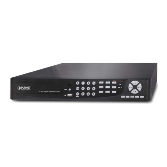
- Page 1 8 / 16-CH H.264 Digital Video Recorder DVR-872 / DVR-1672...
- Page 2 PLANET has made every effort to ensure that this User’s Manual is accurate; PLANET disclaims liability for any inaccuracies or omissions that may have occurred.
- Page 3 Trademarks The PLANET logo is a trademark of PLANET Technology. This documentation may refer to numerous hardware and software products by their trade names. In most, if not all cases, these designations are claimed as trademarks or registered trademarks by their respective companies.
- Page 4 This symbol is intended to alert the user to the presence of unprotected “Dangerous voltage" within the product's enclosure that may be strong enough to cause a risk of electric shock. This symbol is intended to alert the user to the presence of important operating and maintenance (servicing) instructions in the literature accompanying the appliance.
-
Page 5: Table Of Contents
TABLE OF CONTENTS Chapter 1 FEATURES ........................1 Chapter 2 PACKING DETAIL ......................2 Chapter 3 LOCATION AND CONTROL .................... 3 3.1 Front Panel Controls ......................3 3.2 Real Panel Connectors ......................5 3.3 Remote Control ........................6 3.4 Mouse Control........................9 3.5 Playback Mode........................11 3.6 PTZ Mode ..........................12 Chapter 4 INSTALLATION ...................... - Page 6 7.13 DVR Connection Information Setup..................61 7.14 Group Administration ......................61 7.15 eMap Setup ........................63 7.16 Remote-Site Playback ......................63 7.17 HDD Playback ........................65 7.18 File Playback........................66 7.19 Event Playback........................67 7.20 Snapshot Data ........................68 7.21 Recording Data ........................68 Chapter 8 NETWORK SURVEILLANCE..................69 8.1 AP Software Installation and Setup..................69 8.2 AP Software Operation ......................70 Chapter 9 Mobile Application ......................
-
Page 7: Chapter 1 Features
Chapter 1 FEATURES Two USB ports (for mouse usage and backup). Dual streaming enhances the speed of network transmission Built-in VGA up to 1280x1024 resolution Individual setup of resolution, frame rate and video quality for each channel ... -
Page 8: Chapter 2 Packing Detail
4. Remote Control 5. HDD Kit x 1 6. Power Adapter & Power Cord 7. Battery x 2 8. SATA Cord x2 (DVR-872) 9. HDD Rack x 4 (DVR-872) 10. I/O Cable SATA Cord x3 (DVR-1672) HDD Rack x6 (DVR-1672) -
Page 9: Chapter 3 Location And Control
Chapter 3 LOCATION AND CONTROL 3.1 Front Panel Controls DVR-872/ DVR-1672 Item Description A DVD-RW drive can be installed in the front DVD-RW Slot vancant drive bay. (Optional) IR RECEIVER Input sensor for the remote control. Press EJECT button to open/close the DVD-RW EJECT drive. - Page 10 PLAY Start playing back. Enter search menu screen, use Up/ Down SEARCH button to navigate. Press ENTER to access selected item. Exit various functions and menu screen ESC/ BACKUP Video data storage backup. ENTER/ MODE( ) Switch to full screen and quad screen. MENU/ PAUSE Enter menu mode, use Up/ Down button to MENU/...
-
Page 11: Real Panel Connectors
3.2 Real Panel Connectors 3.2.1 8–CH Digital Video Recorder: (DVR-872) 3.2.2 16–CH Digital Video Recorder: (DVR-1672) -
Page 12: Remote Control
3.3 Remote Control... - Page 13 Remote Controller – Button Definition ○ Start/ Stop Recording. ○ STATUS Display Status. Camera Select / Numeric Button. ○ CAMERA BUTTONS Press [+10] button to select channels. ○ MUTE Switch to 1-CH Audio Out/ Turn Off Live Audio. Enable/ Disable On Picture-In-Picture Format. ○...
- Page 14 ○ IRIS - PTZ Iris-Close. ○ ZOOM + PTZ Zoom-In. ○ ZOOM - PTZ Zoom-Out. ○ FOCUS + PTZ Focus-In. ○ FOCUS - PTZ Focus-Out. Lens PreSet Point Setup Press PRESET button+ 2 numeric numbers to save current lens location ○...
-
Page 15: Mouse Control
3.4 Mouse Control Live Mode Single Channel Display Move the cursor to the desired channel and double left click. Change from Single-Channel Double left click to Multi-Channel Display Mouse – Menu Mode Enter Menu setup Right click Select/ Enter Left click Return to Previous Page Right click Mouse –... - Page 16 LOCK, activate the key lock. Full screen display, multiple clicking to switch channels Quad display. 9CH Split-screen display 13CH Split-screen display 16CH Split-screen display Mouse – GUI Hints and Tips Recording is on Number represents the current selected LIVE audio channel Live Audio is off Motion detected on the channel Sensor triggered on the channel...
-
Page 17: Playback Mode
3.5 Playback Mode Playback – Quick Function Icon Press「 」button to Fast Rewind Speed : 2x, 4x, 8x, 16x, 32x, 64x Press「 」button to Fast Forward Speed : 2x, 4x, 8x, 16x, 32x, 64x Press「PLAY」/ 「 」button to Play/ Pause Playback 「... -
Page 18: Ptz Mode
3.6 PTZ Mode PTZ – Remote Controller Control / SLOW Move PTZ up. Move PTZ down. Move PTZ to the left. Move PTZ to the right. PTZ zoom-in. ZOOM + PTZ zoom-out. ZOOM - PTZ focus-in. FOCUS + FOCUS - PTZ focus-out. - Page 19 PTZ – Quick Function Icon Exit PTZ Mode and back to the LIVE mode Preset number N. (1~64) Go to preset number N. Set current PTZ location at preset number N. [TOUR] icon, click to activate preset tour Same as [PIP]. Set current PTZ location as the starting point of the line-scan.
-
Page 20: Chapter 4 Installation
Chapter 4 INSTALLATION 4.1 System Configuration 4.1.1 8–CH Digital Video Recorder: 4.1.2 16–CH Digital Video Recorder:... -
Page 22: Hard Disk Installation
4.2 Hard Disk Installation Remove the upper case. Step 1: Lock the HDD holder symmetrically onto both sides of the HDD. Step 2: Lock the screw Step 3:Insert the SATA cable and power cable onto the SATA HDD Step 4: Place the HDD on the HDD plate of the removed case and connect the power and the SATA cable. - Page 23 The installation has completed. Step 6: DVR-872 DVR-1672 HDD0 HDD1 HDD1 HDD0 HDD2 DVD BUNNER DVD BUNNER...
-
Page 24: Chapter 5 Basic Operation And Menu Setup
Chapter 5 BASIC OPERATION and MENU SETUP 5.1 Main Menu Setup To enter the main menu and setup the DVR, please log-in account and enter user password. The default password of the administrator is “123456”. Please refer to “Account Setup” for related setup of other log-in users. Main Menu –... -
Page 25: Record Setup
Main Menu – Remote Controller and Front Panel Control (Click MENU button to enter Quick Setup Menu ) Switch to different options under one item Switch to different items MENU Press to confirm setup (OK) Press to cancel setup (CANCEL) Enter the menu, or display virtual keyboard ENTER 5.2 Record Setup... - Page 26 Item Description Select STOP to stop recording or OVERWRITE to reuse the HDD when HDD is full. [Stop] : Stop Recording HDD FULL [Overwrite] : Start to overwrite beginning from the oldest data of HDD, and continue to record. OSD Position X Set time stamp of OSD position X OSD Position Y Set time stamp of OSD position Y...
- Page 27 5.2.1 Quality & Frame Rate Setup Item Description View Normal / View Event Setup resolution, quality and FPS separately for different record type. Check/ Uncheck the box will enable/ disable recording of that channel. Resolution Choose record resolution, this value will be used by each channel. Quality Choose from Below Basic / Basic/ Normal/ High/ Highest.
-
Page 28: Event Setup
5.3 Event Setup Item Description Motion Setup Enter to set up motion detection Sensor Setup Enter to set up sensor detection 5.3.1 Motion Setup... -
Page 29: Motion Area Setup
Item Description Alarm Duration(Seconds) Alarm duration time (1~60 seconds). Check the box to Enable/ Disable popup screen function for all channels. Motion Popup When motion is detected in LIVE mode, the detected channel image will popup in full screen display. Enable Check the box to Enable/ Disable motion detection for each channel. -
Page 30: Sensor Setup
Item Description Mask Mouse Selection Select to mask the mouse selected area. All Area Detection Select all the images as motion detection area. Mask All Area Cancel all motion detection images on the screen. Continue Continue setup. Save setup and exit setup page. Exit &... -
Page 31: Schedule Setup
5.4 Schedule Setup Apart from manual recording, you can also setup the recording time by weeks and schedule recordings include: normal, motion detection, and sensor detection. Item Description Click or press ▼ to select Page. Each page provides 10 schedules for Page setup. - Page 32 5.4.1 Schedule Record Setup Click on the time icon on the left side. The setup menu will be displayed. You can have detail setup by dates, time and event. Item Description Enables schedule recording according to the time Enable Schedule Record schedule (shown above).
-
Page 33: Camera Setup
5.4.2 Holiday Setup Since holidays are different between countries and regions, you can setup the holiday of your location accordingly (Maximum Setup: 50). 5.5 Camera Setup... -
Page 34: Account Setup
Item Description Mask Check the box to Enable/ Disable mask function for LIVE mode Drag the white bar or press ◀ ▶ to adjust Sharpness of your camera from Sharpness value 0 to 15. The default value is 1. Drag the white bar or press ◀ ▶ to adjust Brightness of your camera from Brightness value 0 to 255. - Page 35 Item Description Check to activate the user’s account. User Name Edit the user name. Password Enter to set up password for each user. Permissions Enter to setup Permissions for each user. Change Admin Password Enter to change administrator’s password. 5.6.1 Permission Setup The Account Setup is set to provide individual user (maximum of 4 users) role-based permissions, including access to Setup menu, Network operation, and PTZ function, Playback, Utility, Backup and Mask on specific channels while playing back.
-
Page 36: Network Setup
5.7 Network Setup... - Page 37 Item Description Setup mode for network connection: DHCP、LAN、ADSL. Connect type HTTP Setup Enter to set up HTTP for remote access into DVR. DDNS Setup Enter to Enable/ Disable DDNS function and set up. Mail Setup Enter to Enable/ Disable Email notification and setup. 5.7.1 Networking Setup The DVR supports DHCP, LAN and ADSL access for network connection.
- Page 38 5.7.1.2 LAN Select LAN for network connection, the following information is required. Item Description IP Address Enter IP address provided by ISP Subnet Mask Enter IP address of Subnet Mask provided by ISP Gateway Enter IP address of Gate way provided by ISP Enter DNS address provided by ISP.
- Page 39 Item Description User Name Enter user name provided by ISP Password Enter password provided by ISP 5.7.2 HTTP Setup...
- Page 40 Item Description Check to enable HTTP server. Users can remotely access into the DVR Enable HTTP Server over the network if the HTTP function is activated. Enter a valid port value from 1 up to 65535. The default value is 80. Port Quality and Frame Rate Setup for Network Transmission Check to activate the transmission of each camera.
- Page 41 5.7.4 Mail Setup E-mail can be used as a form of notification when an event occurs (VLOSS, MOTION, and SENSOR). Item Description Check the box to enable/disable E-mail Notification function. Enable E-mail Notification SMTP Server Enter to set up SMTP Server name. Port Default is 80.
-
Page 42: Ptz & Rs-485 Setup
circumstances happen: Motion, Sensor and Vloss (Video Loss). Receiver E-mail Enter to set up e-mail addresses for up to 10 receivers individually. 5.8 PTZ & RS-485 Setup The DVR allows users to control PTZ functions of your camera. To enable PTZ function, the 485 cable should be connected to the RS-485 port of DVR. -
Page 43: System Setup
5.9 System Setup Item Description DVR Name The name of DVR will be shown when users login from remote access. The location of DVR will be shown when users login from remote access DVR Location Language Click or press ▼ to select OSD language. Setting remote controller ID to match the remote code definition Remote ID retrospectively to particular DVR. -
Page 44: Display Setup
Show Date/Time Turn On / Off channel name display Show Channel Name Auto / NTSC / PAL video system setting available to DVR-872) Video System Make the display more suitable for CRT monitor. available to DVR-1672) Set up the color of border in LIVE , PLAYBACK mode.(black, dark grey, Border Color light grey, and white)... - Page 45 5.9.2 Date/ Time Setup Item Description Hour Format 12HOURS/ 24HOURS MM-DD-YY/DD-MM-YY/YY-MM-DD Date Format Choose the position of Time and Date display Date/Time Position Change Date & Time Setup time and date of DVR Time Zone Setup Set up GMT and Daylight Saving Time. Internet Time Setup Setup automatic synchronization with internet server...
- Page 46 5.9.2.1 Change Date & Time Users are allowed to setup date and time of the DVR. 5.9.2.2 Time Zone Setup In time zone setup, users can change the time zone and activate Daylight Saving Time function according to your DVR location. Item Description Select Time Zone...
- Page 47 5.9.2.3 Internet Time Setup Synchronize your DVR time with internet time server. Item Description Check to enable DVR automatic synchronization function. Select this Automatic Synchronization option to enable the function, DVR will automatically synchronize the time upon rebooting or by every 24 hours after booting. Date and Time show on DVR will immediately correspond with those in Update Now internet server.
- Page 48 5.9.3 Device Setup...
- Page 49 Item Description Mouse Speed Adjust the mouse moving speed Buzzer & Relay Setup Key Tone Enable/ Disable keystrokes. Enable/ Disable buzzer operation when the alarm is triggered for HDD Alarm Buzzer error, sensor, motion and vloss (Video Loss). Enable/ Disable the signal to be sent to the RELAY OUT blocks when the Alarm Relay alarm is triggered for HDD error, sensor, motion and vloss.
-
Page 50: Utility Setup
5.10 Utility Setup Item Description HDD Initialization Select to enter hard disk initialization menu. Please stop recording before entering this menu. Enter the menu, system will show all the data (model/ volume) of HDD that is installed in the DVR. Check the HDD you’d like to initialize, and then press “Start”. -
Page 51: Diagnostic
5.11 Diagnostic Item Description The current firmware version of DVR Version The connected IP address of DVR. If disconnected from network, the IP Address screen will display” NETWORK DISCONNECT”. MAC Address MAC Address of DVR HDD Volume The capacity of HDD HDD Used Rate Percentage of space used on HDD. -
Page 52: Chapter 6 Search & Backup
Chapter 6 SEARCH & BACKUP 6.1 Search Setup Item Description Press to enter event search menu. Event Search Time Search Press to enter time search menu. 6.1.1 Event Search... - Page 53 The DVR automatically records events with type, time and channel information included. If there is recording data for an event, a yellow signal icon will be shown on the left side of time information. Rest your cursor under the line and press “enter”, or left click your mouse to playback the recording data.
- Page 54 setting up “criteria”. Setup “start time” and “end time” for each event search, then the search result will be limited to this specific period of time. Only events and channels that are checked will be sorted in event search as well. 6.1.2 Time Search TIME SEARCH, you can search for a specific time of the recording data to playback.
-
Page 55: Backup Setup
6.2 Backup Setup User can back-up any segment of recorded data in a specified time frame. To do so, connect a USB to the DVR. The format of backup file is IRF file and can be played by “DVRemoteDesktop.exe” or “iCMS”. Item Description From... -
Page 56: Chapter 7 Icms Installation And Usage
Chapter 7 iCMS Installation and Usage DVR-462 has provided a simple use and powerful utility called – iCMS. When this utility installed to Windows platform, user can get more functions than on the web browser. When you want to fully control your DVR-462, you may install the iCMS into your PC and refer to instructions below to know and manage theose functions in the iCMS. - Page 57 Step 5: Select “Browse” to change installation path if needed. To check available space on hard disk, please select “Disk Cost” then please select “Next” to the next step. Step 6:”Confirm Installation” window shows. Select ‘Next’ then the installation starts.
-
Page 58: Icms Login And Environment
Step 7: Select ‘Close’ to finish installation when the “Installation Complete” window shows. 7.2 iCMS Login and Environment To enter iCMS, the administrator’s user name and password are required. The defaults are ‘admin’ and ‘123456’. - Page 59 After successful login, the following image is shown on your screen: ③ ① ② ④ ⑤ DVRs, Groups & Information about DVRs, groups and events. See “7.3 Events Groups & Events” for more details. Information about local PC’s hard disk, volume, PC information and recording...etc.
-
Page 60: Groups & Events
7.3 Groups & Events Icon Description View list of logged in DVR/ Group. View Logs: DVR event information list. 7.4 View DVR/ Group List Single left click on ‘DVR’ or ‘Group’ will expand/ shrink the entire DVRs and groups list. On the DVR list, double left click on a connected DVR will show its image in the main display. -
Page 61: Event View
7.5 Event View This window lists all the events recorded on the DVR. Each DVR has a list of different categories of events. According to Remote in/ Remote out, Video Loss, Motion, Sensor, and Other(Power Reset, Key lock, Key unlock, HD Full). 7.6 Local PC Information and Control Located on the left lower corner of the screen, please see the chart below: Icon... -
Page 62: Main Display
7.7 Main Display The main display area is where the live image of DVR is shown. You can drag to change the location of the screen for each channel and turn On/Off audio signal by clicking the mouse. 7.8 Audio Control In live mode, you can turn On/ Off the audio signal of Ch1~Ch4 (4CH DVR supports only 1Channel audio recording): 」Audio signal is On... -
Page 63: Emaps
7.9 eMaps In LIVE view, press「 」to show eMap window. If a channel has e-Map settings added, a drop-down menu will appear showing the related e-Map names added in this channel. The channel that has not been added with any e-Map settings will have "No eMaps"... -
Page 64: Ptz Control
7.10 PTZ Control Right mouse click on the screen, PTZ control icon will appear, as shown below: Icon Description 8 Directional PTZ Movement Button ZOOM+:Zoom In ZOOM-:Zoom Out Preserved Function FOCUS+:Focus Near FOCUS-:Focus Far Preserved Function Set PTZ Preset 16 PTZ Preset Points Goto PTZ Preset 16 PTZ Goto Preset Points Activate Auto Tour... -
Page 65: Operation Bar
7.11 Operation Bar 10 Operations listed as below: Icon Description User Administration. Please see「7.12 User administration」 DVR Administration. Please see「7.13 DVR Administration」 Group Administration. Please see「7.14 Group Administration」 eMap Administration. Please see「7.15 eMap Setup」 Remote Playback. Please see「7.16 Remote-Site Playback」 HDD Playback. -
Page 66: User Administration
7.12 User administration Before the iCMS can be used on a PC, user accounts should be added with proper authority. Each user should be assigned with a password and optionally a description. If a user does not have certain authority assigned, he/ she will not be able to operate the corresponding function on the Operation Bar. -
Page 67: Dvr Connection Information Setup
7.13 DVR Connection Information Setup You can add or delete the DVR connection, information and description editing, also enter names of the channels (Please select Generic DVR for DVR Model). After setup, please click "OK" to store setup. 7.14 Group Administration A ‘Group’... - Page 68 Step 4: Click “OK” to return to the previous window. Step 5: Select a display mode, system will auto select. Step 6: Drag a channel from the lower left panel into the main display to a preferred location. Or, change the channel location in the main display by mouse dragging. Step 7: You can ‘Select’...
-
Page 69: Emap Setup
7.15 eMap Setup If the DVR has the sub-region, or would like to have a picture on the background to monitor the channel, you can use the eMap. Steps: 1. Click [ ] icon to select a path of the window picture. 2. - Page 70 Icon Description Start Playback Pause Stop playback Fast forward Fast rewind...
-
Page 71: Hdd Playback
7.17 HDD Playback You can directly play the recording data in the HDD that’s uninstalled from DVR by iCMS. See the picture below, the left part of the screen shows the recording data in a list form that’s separated by hour and the right part is the main display. You can change the display modes and play files fast forward or rewind. -
Page 72: File Playback
7.18 File Playback You can play the recorded *.irf files by “File Play” in iCMS. It allows you to change the display mode, forward or rewind the file and drag the time bar. Icon Description Start Playback Pause Stop playback Fast forward Fast rewind... -
Page 73: Event Playback
7.19 Event Playback You can play the event recorded by the DVR. Steps: 1. Select DVR. 2. Select date. 3. Double-click on the selected “Event type” (table on the left hand side, bottom row), video will be shown on the right side of the screen. 4. -
Page 74: Snapshot Data
7.20 Snapshot Data It can display all the snapshots you’ve taken, into “Snapshot Data”. You can review, delete or save as other files. 7.21 Recording Data It can play all the recording files you’ve recorded, into “Recording Data”. You can play or delete them. -
Page 75: Chapter 8 Network Surveillance
Chapter 8 NETWORK SURVEILLANCE 8.1 AP Software Installation and Setup Step 1:Enter the IP address of the DVR in the IE browser. Step 2: A window will pop-up. Please enter the user name and password. Default user name is admin and password is 123456. Other related setup about user account and password, please refer to “5.6 Account Setup“. -
Page 76: Ap Software Operation
Step 3: You’ve logged into the DVR 8.2 AP Software Operation User-friendly operation, DVR remote interface provides the DVR with the same local client interface. - Page 77 8.2.1 Remote Record Click Record icon to select between 3 recording options (Record On/ Off, Record to Local…, Screen Snapshot [F2]). Record switch can activate DVR client to record, record to local client can be backed up onto the PC, may also use snapshot to capture video image onto the PC.
- Page 78 8.2.3 Full Screen Click Full Screen icon to enlarge the screen to full screen display. 8.2.4 Camera Name A variety of languages can be used to setup the PC client camera names; and simultaneously changes the display of the local client DVR. 8.2.5 Remote-Site Backup...
-
Page 79: Chapter 9 Mobile Application
Select backup function to backup the data to PC. Chapter 9 Mobile Application You can remotely monitor all channels of the DVR through your mobile device. The required mobile application is from the DVR manufacturer and it supports mobile OS for both Windows mobile 5.0 above and Symbian. - Page 80 9.1.2 Mobile Application Operation After the installation, enter Program Files menu in your mobile device to run a file called “H264 MIDlet”. Select “Menu” at the right lower corner of your mobile screen, 4 commands, Login Add Modify and Delete, will show up. 9.1.2.1 Add New Login DVR To log into the DVR, you need to enter the logging-in DVR information.
- Page 81 Note: Live images can not be displayed in your mobile when the recoding is set to off on local DVR. 9.1.2.3 Modify the Login Information of the DVR You can use “Modify” command to change the login information of the DVR. The dialogue is identical to that of “Add”...
- Page 82 9.1.2.4 Delete the Login Information of the DVR “Delete” command can be used to remove the DVR information when it is no longer useful. Select the DVR on the name list, then choose “Delete”. 9.1.3 Live Monitoring Operation This paragraph describes some operation under the LIVE monitoring mode in your mobile device.
- Page 83 9.1.3.3 Channel Display Select “Single” under the “Menu”, all channels will be listed for you to choose from. PS. Live images can not be displayed in your mobile when the recoding is set to off in local DVR. 9.1.3.4 Size of Image The screen size of different mobile device can be different.
- Page 84 9.1.3.5 Rotate the image Live image can be displayed by normal image or rotate to 90 degrees. Select “Rotate” under the “Menu” for this operation. 9.1.3.6 Alarm This application will not only allow user to remotely monitor through mobile device but receive the alarm that has been triggered by events such as Motion Detected, Sensor Triggered and Vloss (Video Loss).
-
Page 85: For Windows Mobile System
9.2 For Windows Mobile System There are two kinds of applications for Window Mobile OS: JPEG compression and H.264 compression. The one for H.264 compression can transfer both audio and video signal to your mobile device. System Requirement: Mobile device OS:Windows mobile system 5.0 and above. Mobile device need to support internet: GPRS/3G/Wifi…... -
Page 86: Mobile Application Operation
9.2.2 Mobile Application Operation After the installation, enter the Program Files menu in your mobile device to run files named “Jrviewer” and “H264Pocket”. This application allows you to remotely logon and monitor the DVR. Press “OK” to bring up the operation menu; see chart the below for further information. Item Function Description... - Page 87 bar, alarm, full screen display….etc 9.2.3.1 jrviewer Operation under the LIVE monitoring Item Function Description Channel Display for CH 1~16 Choose from CH1~16 to display 1~16 Original:image size as original Stretch:stretch the size as full screen Screen Size of image Fit: resize the image to fit the screen Change the quality of image.
-
Page 88: Operation Under The Live Monitoring For H264 Pocket
9.2.3.2 Operation under the LIVE monitoring for H264 Pocket Item Function Description Channel Display for CH 1~16 Choose from CH1~16 to display. CH1 can receive audio signal. 1~16 Graphical icons indicated below will be shown on the status bar if there is event such as motion detected, sensor triggered and video loss to be detected on any channel. -
Page 89: Appendix A: Product Specification
Check this function to choose one channel to display in full Full Screen Full screen display screen. Appendix A: Product Specification Model DVR-872 DVR-1672 CONNECTOR Video System Auto Detect NTSC / PAL Switch 8CH BNC 16CH BNC Video Input 1CH BNC(MAIN / SPOT)... - Page 90 720x480, 720x240, 360x240 (NTSC) Resolution 720x576, 720x288, 360x288 (PAL) 60, 120, 240 (NTSC) 120, 240, 480 (NTSC) Frame Rate 50, 100, 200 (PAL) 100, 200, 400 (PAL) Highest, High, Normal, Basic, Below Basic Quality Record Mode Manual, Schedule, Event(motion detection/sensor) Pre-Alarm Recording 16MB (around 10 sec) Post-Alarm...
Need help?
Do you have a question about the DVR-872 and is the answer not in the manual?
Questions and answers