Table of Contents
Advertisement
S
N
UPER
ELECTRIC, AIRLESS PAINT SPRAYER
3000 psi (210 bar, 21 MPa) Maximum Working Pressure
Model 820169, Series D
Complete sprayer with hose, gun,
RAC IV DripLess
Tip Guard and SwitchTip
Model 824175, Series A
Upright cart; complete sprayer with hose, gun,
RAC IV DripLess
Tip Guard and SwitchTip
All models are not available in all countries
U.S. PATENT NO. 4,323,741; 4,397,610 PATENTED
1983, CANADA AND OTHER PATENTS PENDING
Related Manuals
Operator
. . . . . . . . . . . . . . . . . . . . . . . . . . .
Displacement Pump
. . . . . . . . . . . . . . . . .
FTx Spray Gun
. . . . . . . . . . . . . . . . . . . . .
Spray Tip
. . . . . . . . . . . . . . . . . . . . . . . . . . .
Component Function and Identification
. . . . . . . . . . . . . . . . . . . . . . . . . . . . . . . . . . . . .
. . . . . . . . . . . . . . . . . . . . . . . . . . . . . . . .
. . . . . . . . . . . . . . . . . . . . . . . . . . . . . . . . . . . . .
. . . . . . . . . . . . . . . . . . . . . . . . . . . .
. . . . . . . . . . . . . . . . . . . . . . . . . . . . .
. . . . . . . . . . . . . . . . . . . . . . . . . . . .
. . . . . . . . . . . . . . . . . . . . . . . . . . . . . . . .
The SHERWIN-WILLIAMS COMPANY, CLEVELAND, OHIO 44115
INSTRUCTIONS-REPAIR
This manual contains important
warnings and information.
READ AND RETAIN FOR REFERENCE
SP
OVA
824112
308190
308645
308644
Table of Contents
. . . . . . . . . . . .
. . . . . . . . . . . . . . . . . . . . . .
. . . . . . . . . . . . . . . . . . . . .
10
. . . . . . . . . . . . . . . . . . . . .
12
13
14
14
14
. . . . . .
15
COPYRIGHT 1998, GRACO INC.
2
. . . . . . . . . . . . . . . . . . . . . . . . . . . . . .
3
4
. . . . . . . . . . . . . . . . . . . . . . . . . . . . . . . . .
5
. . . . . . . . . . . . . . . . . . . . . . . . . . . . . . . . . . .
9
Model 820169 Sprayer Parts Drawing
Model 820169 Sprayer Parts List
Model 824175 Sprayer Parts Drawing
Model 824175 Sprayer Parts List
. . . . . . . . . . . . . . . . . . . . . . . . . . . . . . . .
. . . . . . . . . . . . . . . . . . . . . . . . . . . . . . . . . . .
OWNER'S
MANUAL
824113
Rev A
Model 824175
8733
Model 820169
. . . . . . . . . . . . . . . . . . . . . . . . . . .
. . . . . . . . . . . .
. . . . . . . . . . . . . . . .
. . . . . . . . . . . .
. . . . . . . . . . . . . . . .
. . . . . . . . . . . . . . . . . . . . .
16
17
17
18
19
20
21
22
23
23
24
Advertisement
Table of Contents

Related Manuals for Sherwin-Williams 820169 D Series


Summary of Contents for Sherwin-Williams 820169 D Series
-
Page 1: Table Of Contents
..... Drive Housing, Connecting Rod, Crankshaft ..The SHERWIN-WILLIAMS COMPANY, CLEVELAND, OHIO 44115 COPYRIGHT 1998, GRACO INC. -
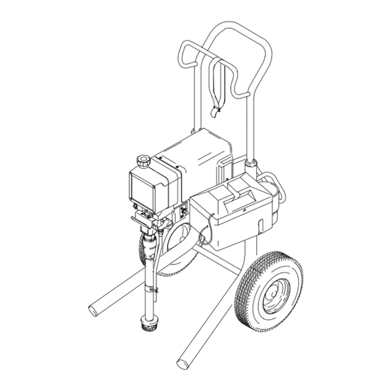
Page 2: Model
Component Identification and Function Model 820169 Shown 06973 Fig. 1 Motor DC motor, 120 Vac, 15A, 1 phase Drive Assembly Transfers power from DC motor to the displacement pump Pressure Adjusting Knob Controls fluid outlet pressure ON/OFF Switch Power switch that controls 120 Vac power to sprayer Fluid Outlet Hose and spray gun is connected here Displacement Pump... -
Page 3: General Repair Information
General Repair Information CAUTION WARNING To reduce risk of pressure control malfunction: EXPLOSION HAZARD Motor and drive housing are very hot Use needle nose pliers to disconnect a wire. Never during operation and could burn skin if pull on wire, pull on connector. touched. -
Page 4: Grounding
Grounding WARNING Improper installation or alteration of grounding plug Grounded results in risk of electric shock, fire or explosion Outlets that could cause serious injury or death. Grounding Prong 1. Models 820169 and 824175 require a 120 VAC, 50/60 Hz, 15A circuit with a grounding receptacle. Fig. -
Page 5: Troubleshooting
Troubleshooting Relieve pressure; page 3. Basic Problem Solving Check everything in the troubleshooting table before disassembling the sprayer. TYPE OF PROBLEM WHAT TO CHECK WHAT TO DO If check is OK, go to next check When check is not OK, refer to this column Fluid pressure 1. -
Page 6: Pressure Transducer
Basic Problem Solving TYPE OF PROBLEM WHAT TO CHECK WHAT TO DO If check is OK, go to next check When check is not OK, refer to this column Electrical 5. Motor armature commutator for burn spots, 5. Remove motor and have motor shop (continued) gouges and extreme roughness. - Page 7 Intermediate Problem Solving TYPE OF PROBLEM WHAT TO CHECK WHAT TO DO If check is OK, go to next check When check is not OK, refer to this column Low output 3. Release gun trigger. Observe resting position of 3. If pump consistently comes to rest with (continued) pump rod (107).
- Page 8 Intermediate Problem Solving TYPE OF PROBLEM WHAT TO CHECK WHAT TO DO When check is not OK, refer to this column If check is OK, go to next check 1. Spray tip worn beyond sprayer pressure capa- 1. Replace spray tip. Spray Pattern Variations bility.
-
Page 9: Motor Test
Motor Test Relieve pressure; page 3. For checking armature, motor winding and brush electrical continuity. Setup Remove the drive housing. See page 15. This is to ensure that any resistance you notice in the armature test is due to the motor and not to worn gears in the drive housing. -
Page 10: Motor Brush Replacement
Motor Brush Replacement NOTE: Replace brushes when worn to about 0.5 in. Motor lead; do not disconnect (12.5 mm). Always check both brushes. Brush Repair Minimum 0.5” (12.5 mm) Kit 236–967, which includes spring clip 112–766, is available for motors manufactured by Pacific Scientific. Included in Brush Repair Kit 236–967 NOTE: Replacement brushes may last only half as... - Page 11 Motor Brush Replacement 9. Test the brushes. WARNING a. Remove the pump connecting rod pin (17). See Fig. 9, page 12. MOVING PARTS HAZARD Do not touch the brushes, leads, springs b. With the sprayer OFF, turn the pressure con- or brush holders while the sprayer is trol knob fully counterclockwise to minimum plugged in to reduce the risk of electric...
-
Page 12: Displacement Pump Repair
Displacement Pump Repair 2. Align the hole in the rod (107) with the connecting rod assembly (15). Use a screwdriver to push the Relieve pressure; page 3. retaining spring (18) up and push in the pin (17). Push the retaining spring (18) into place around the connecting rod. -
Page 13: Motor Replacement
Motor Replacement 10. Assemble the drive housing to the motor. Follow steps 8 to 10 on page 15. Relieve pressure; page 3. 11. Connect the wires in the junction box. Refer to Fig. 13 on page 14. Install the junction box. NOTE: See Fig. -
Page 14: Motor Start Board
6. Install the junction box. Be sure no leads are Motor Start Board pinched against the motor or by the motor start board. Also be sure the gasket (89) is installed. Relieve pressure; page 3. On/Off Switch NOTE: See Fig. 13 for this procedure. NOTE: See Fig. -
Page 15: Drive Housing, Connecting Rod, Crankshaft
Drive Housing, Connecting Rod, Crankshaft CAUTION Relieve pressure; page 3. Do not allow the gear (16) to fall; it may stay at- tached to the drive housing or to the motor. Removal Do not lose the thrust balls (11a or 4a) or let them fall between the gears, which will damage the drive hous- NOTE: Inspect parts as they are removed. -
Page 16: Pressure Control
Drive Housing, Connecting Rod, Crankshaft REF A Torque to 2.4 N.m (21 in–lb) Quantity of three Quantity of one Apply a total of 3 fl. oz.(29 cc) of grease to gears. Note: Filter not shown 02815 Fig. 15 Pressure Control 8. -
Page 17: Pressure Transducer
Pressure Transducer Relieve pressure; page 3. NOTE: See Fig. 17 for this procedure. 1. Remove the displacement pump. See page 12. 2. Use a pull–twist motion to remove the transducer (29) from the pump manifold (101). 3. Clean paint residue from the hole in the manifold; do not scratch the surface of the hole. -
Page 18: Drain Valve
Drain Valve Repair Relieve pressure; page 3. 1. Unscrew the spring retainer from the valve body. Remove the spring, washers and stem/ball. Clean any debris from the ball or seat area. 2. If replacing the gasket (42a) or seat (42b), pry out Apply thread sealant the gasket. - Page 19 Sprayer Parts Drawing Model 820169, Series D Label See detail on page 20 REF 33 REF 32 OUT- SIDE LABEL INSIDE LABEL 06974...
- Page 20 Sprayer Parts List Model 820169, Series D Ref. Ref. Part No. Description Qty. Part No. Description Qty. 111700 GRIP, handle 224807 BASE, valve 237458 MOTOR KIT 111600 PIN, grooved, 3/32 x 1” Includes items 4a to 4f 187625 HANDLE, drain valve 100069 .
- Page 21 Sprayer Parts Drawing Model 824175, Series A on opposite side on opposite side on opposite side OUTSIDE LABLE INSIDE LABLE Label See page 22 for detail...
- Page 22 Sprayer Parts List Model 824175, Series D Ref. Ref. Part No. Description Qty. Part No. Description Qty. 192027 SLEEVE, cart 111617 STRAIN RELIEF BUSHING, 3/8–18 npt 237458 MOTOR KIT Includes items 4a to 4f 105679 SWITCH, ON/OFF 100069 . BALL, sst, 1/4” dia. 235035 GROUND HARNESS 111616...
-
Page 23: Technical Data
Technical Data DANGER LABELS An English language DANGER label is on your Power Requirements ....120 VAC, 60 Hz, sprayer. If you have painters who do not read 1 phase, 15A minimum English, order one of the following labels to ap- Generator... -
Page 24: Sherwin-Williams Warranty
All written and visual data contained in this document reflects the latest product information available at the time of publication. Graco reserves the right to make changes at any time without notice. The SHERWIN-WILLIAMS COMPANY, 101 PROSPECT AVENUE, CLEVELAND, OHIO 44115 PRINTED IN U.S.A. 824113 January 1999...
Need help?
Do you have a question about the 820169 D Series and is the answer not in the manual?
Questions and answers