Table of Contents
Advertisement
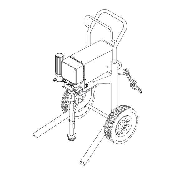
ELECTRIC, 120 VAC
ULTIMATE Plus + 600
Airless Paint Sprayer
3000 psi (210 bar) Maximum Working Pressure
Model 820–206 and 820–208, Series B
Basic sprayer only
Model 820–206
The SHERWIN-WILLIAMS COMPANY, CLEVELAND, OHIO 44115
This manual contains important
warnings and information.
READ AND RETAIN FOR REFERENCE
03193A
OWNER'S MANUAL
820–204
Supercedes Rev. G, H & J
U.S. PATENT NO. 4,323,741, 4,397,610
PATENTED 1983, CANADA
AND OTHER PATENTS PENDING
Model 820–208
Rev. K
04512A
Advertisement
Table of Contents

Related Manuals for Sherwin-Williams 820–206


Summary of Contents for Sherwin-Williams 820–206
- Page 1 AND OTHER PATENTS PENDING ELECTRIC, 120 VAC ULTIMATE Plus + 600 Airless Paint Sprayer 3000 psi (210 bar) Maximum Working Pressure Model 820–206 and 820–208, Series B Basic sprayer only 03193A 04512A Model 820–206 Model 820–208 The SHERWIN-WILLIAMS COMPANY, CLEVELAND, OHIO 44115...
-
Page 2: Table Of Contents
......Sherwin-Williams Warranty ..... - Page 3 WARNING WARNING INJECTION HAZARD Spray from the gun, leaks or ruptured components can inject fluid into your body and cause ex- tremely serious injury, including the need for amputation. Fluid splashed in the eyes or on the skin can also cause serious injury. Fluid injected into the skin is a serious injury.
-
Page 4: Warnings
WARNING FIRE AND EXPLOSION HAZARD Improper grounding, poor ventilation, open flames or sparks can cause a hazardous condition and re- sult in a fire or explosion and serious injury. If there is any static sparking or you feel an electric shock while using this equipment, stop spray- ing immediately. -
Page 5: Component Function And Identification
Component Function and Identification 04512A Fig. 1 Motor (Under shield shown) DC motor, 120 Vac, 15A, 1 phase Pressure Adjusting Knob Controls fluid outlet pressure ON/OFF Switch Power switch that controls 120 Vac main power to sprayer Drive Assembly Transfers power from DC motor to the displacement pump Fluid Filter Filter of fluid between source and spray gun Fluid Outlet... -
Page 6: Setup
Setup 5. Fill the wet–cup (L). Pry off the wet–cup seal. Fill WARNING the cup 1/3 full with Graco Throat Seal Liquid (TSL) (68) supplied. Install the seal. If you supply your own hoses and spray gun, be sure the hoses are electrically conductive, that the 6. - Page 7 Setup 8. Flush the pump to remove the oil which was left How to use the pressure control in to protect pump parts after factory testing. See The pressure control controls the motor operation so page 12. the sprayer maintains constant fluid pressure at the pump outlet.
- Page 8 Setup Pressure Relief Procedure The tip guard alerts you to the risk of injection and helps prevent placing any part of the body close to the spray tip. The tip guard also adjusts the vertical or hori- WARNING zontal spray pattern. See page 10. The tip guard holds a reversing spray tip.
-
Page 9: Startup
Startup Shown in closed, or spray position. Open, or drain position – Model 820–206 Shown 03193A Fig. 7 Use this procedure each time you start the sprayer to 4. Turn the pressure knob (B) to the minimum help ensure the sprayer is ready to operate and that setting. - Page 10 Startup NOTE: Spray patterns will change as tips wear. WARNING Change the spray tip if adjusting the pressure will not improve the spray pattern. FIRE AND EXPLOSION HAZARD To reduce static sparking and splashing when priming, be sure the spray tip is not installed on the gun, and hold a metal part of the gun firmly to the side of a grounded metal pail.
-
Page 11: Shutdown And Care
Shutdown and Care 8. Coil the hose when storing it, even for overnight, WARNING to help protect the hose from kinking, abrasion, coupling damage, etc. INJECTION HAZARD To reduce the risk of serious injury, WARNING whenever you are instructed to relieve pressure, follow the Pressure Relief INJECTION HAZARD Procedure on page 8. -
Page 12: Flushing
Flushing When to flush CAUTION Determine the material you are going to pump from Column 1, then flush with the material indicated in NEVER leave water or water-based fluids in the Column 2. Depending on what you plan to do next, sprayer if there is a chance it could freeze. - Page 13 Flushing 10. Reinstall the clean filter screen. WARNING FIRE AND EXPLOSION HAZARD 11. Remove and clean the inlet strainer. Wipe paint off To reduce static sparking and splashing, the suction hose and drain hose. always remove the spray tip from the gun, and hold a metal part of the gun firmly to the side of a grounded metal pail when 12.
-
Page 14: Troubleshooting
Troubleshooting WARNING CAUTION PRESSURIZED EQUIPMENT HAZARD Thaw sprayer if water or water-based paint has To reduce the risk of serious injury, frozen in it, due to exposure to low temperatures, always follow the Pressure Relief by placing it in a warm area. Do not try to start Procedure on page 8 before checking sprayer until it has thawed completely or damage or repairing any part of the sprayer. - Page 15 Basic Problem Solving TYPE OF WHAT TO CHECK WHAT TO DO PROBLEM If check is OK, go to next check When check is not OK, refer to this column Electrical 4. Check motor brushes for the following: 4. Refer to page 21. (continued) a.
- Page 16 Intermediate Problem Solving TYPE OF WHAT TO CHECK WHAT TO DO PROBLEM If check is OK, go to next check When check is not OK refer to this column Low Output 1. Check for worn spray tip. 1. Follow Pressure Relief Procedure Warning on page 8, then replace tip.
- Page 17 Intermediate Problem Solving TYPE OF WHAT TO CHECK WHAT TO DO PROBLEM If check is OK, go to next check When check is not OK, refer to this column Low Output 7. Check motor control board (47) by substituting with 7.
- Page 18 Intermediate Problem Solving TYPE OF WHAT TO CHECK WHAT TO DO PROBLEM If check is OK, go to next check When check is not OK, refer to this column Spray Pattern 4. Check pressure adjustment potentiometer (64) by Variations replacing it with a new one. (continued) (continued) 5.
-
Page 19: General Repair Information
General Repair Information 3. Route wires carefully and avoid pinching any WARNING wires between covers. INJECTION HAZARD CAUTION To reduce the risk of serious injury, whenever you are instructed to relieve Improper wire routing can result in poor sprayer pressure, follow the Pressure Relief performance or damage to the pressure trans- Procedure on page 8. -
Page 20: Motor Test
Motor Test Armature Short Circuit Test WARNING Remove the fan cover (B). See Fig.12. INJECTION HAZARD To reduce the risk of serious injury, Spin the motor fan by hand. If there are no shorts, the always follow the Pressure Relief motor will coast two or three revolutions before coming Procedure on page 8 before doing this to a complete stop. -
Page 21: Motor Brushes
Motor Brushes NOTE: Replace brushes when worn to about 12.5 mm 8. Test the brushes. (0.5 in.) . Always check both brushes. Brush Repair Kit a. Remove the pump connecting rod pin (17). 236–967 is available for motors manufactured by b. -
Page 22: Displacement Pump
Displacement Pump NOTE: Packing Repair Kit 235–703 is available. Refer- 6. Use a screwdriver to push the retaining spring (18) ence numbers of parts included in the kit are marked up and push out the pin (17). with an asterisk, i.e., (121*). 7. - Page 23 Displacement Pump Disassembling the pump (See Fig. 19) 1. Remove the intake valve (118). Torque to 50 ft–lb (68 N.m) 2. Loosen the packing nut (102) and plug (123). Apply pipe sealant (42e) 3. Use a plastic mallet to tap the piston rod (107) down, and then pull the rod out through the bottom of the cylinder.
- Page 24 Displacement Pump Do not allow nut (110) CAUTION to move relative to piston (108) when tightening piston against rod. Step 8, tightening the piston valve into the rod, is critical. Follow the procedure carefully to avoid Torque nut damaging the packings by overtightening. against rod to 30 ft–lb (40 N.m)
- Page 25 Displacement Pump *103 104* PLASTIC *105 LEATHER 106* *116 *111 112* *113 PLASTIC LEATHER 116* 114* 125* 126* 122* *119 121* Torque jam nut (117) 73 ft-lb (98 N.m) Torque cylinder (115) into manifold (101) to Lips face down. 53 ft-lb (71 N.m) Lips face up.
-
Page 26: Motor
Motor 9. Remove the two screws (46) and lift the motor off WARNING the cart (1). INJECTION HAZARD 10. Align the new motor with the cart and reinstall the To reduce the risk of serious injury, screws (46). whenever you are instructed to relieve pressure, follow the Pressure Relief 11. -
Page 27: Motor Control Board
Motor Control Board 4. Remove the screw (9) from the ground wire (G) WARNING and remove the board. INJECTION HAZARD 5. Install the new motor control board. Reconnect all To reduce the risk of serious injury, wires and secure it to the junction box (59). whenever you are instructed to relieve pressure, follow the Pressure Relief CAUTION... -
Page 28: Drive Housing, Connecting Rod, Crankshaft
Drive Housing, Connecting Rod, Crankshaft WARNING CAUTION INJECTION HAZARD Do not allow the gear (16) to fall; it may stay at- tached to the drive housing or to the motor. To reduce the risk of serious injury, whenever you are instructed to relieve Do not lose the thrust balls (11a or 4a) or let them pressure, follow the Pressure Relief fall between the gears, which will damage the drive... - Page 29 Drive Housing, Connecting Rod, Crankshaft Note: Filter not shown Torque to 80 in–lb (9 N.m) 02995 Fig. 28...
-
Page 30: Pressure Transducer
Pressure Transducer NOTE: See Fig. 28 and 29 for this procedure. 3. Guide the harness up through the leg and notch of the drive housing (11). Secure the guide wire over NOTE: The pressure transducer (29) cannot be re- the connector. paired or adjusted. -
Page 31: Pressure Transducer Seal
Pressure Transducer Seal NOTE: The PTFE seal is unaffected by most solvents Installation and materials. Replacement of the seal is recom- 1. Lightly coat the cleaned packing recess in the mended only when leakage has occurred. manifold with a light grease or oil. 2. -
Page 32: Suction Hose
Suction Hose (Model 820–206) WARNING CAUTION INJECTION HAZARD Misalignment or cross-threading will damage the parts and/or create shavings which can cause the To reduce the risk of serious injury, o-ring (27) to leak. whenever you are instructed to relieve pressure, follow the Pressure Relief Procedure on page 8. -
Page 33: Drain Valve
Drain Valve Repair WARNING 1. Unscrew the spring retainer from the valve body. INJECTION HAZARD Remove the spring, washers and stem/ball. Clean To reduce the risk of serious injury, any debris from the ball or seat area. whenever you are instructed to relieve pressure, follow the Pressure Relief 2. -
Page 34: Complete Sprayer Parts
Complete Sprayer Parts Model 820–206, Series B 1 Ref 3 Ref 3 Ref 11a 16 04390A Pressure Control Box (Bottom View) 03020... - Page 35 Complete Sprayer Parts Model 820–206, Series B Ref. Ref. Part No. Description Qty. Part No. Description Qty. 236–367 FRAME,cart 112–607 WHEEL, semi–pneumatic 236–510 KIT, shield, motor 235–014 VALVE, drain 187–791 LABEL, DANGER, English 111–699 GASKET, seat valve 187–975 LABEL, WARNING, elec shock 187–615 SEAT, valve, lapped 187–784...
- Page 36 Complete Sprayer Parts Model 820–208, Series B 11a 16 34 13 04513A Pressure Control Box (Bottom View) 03020...
- Page 37 Complete Sprayer Parts Model 820–208, Series B Ref. Ref. Part No. Description Qty. Part No. Description Qty. 236–961 FRAME,cart 187–615 SEAT, valve, lapped 236–510 KIT, shield, motor 224–968 STEM, drain valve 187–791 LABEL, DANGER, English 168–110 O–RING, stem 187–975 LABEL, WARNING, elec shock 110–110 SEALANT, pipe (not shown) 187–784...
-
Page 38: Displacement Pump Parts
Displacement Pump Parts Model 237–662 Series A Ref. Part No. Description Qty. 101 237–661 MANIFOLD, pump 102 176–758 PACKING NUT 103 176–757* GLAND, female, throat 104 176–997* V–PACKING, plastic, throat 103* 105 176–755* V–PACKING, leather, throat 106 176–754* GLAND, male. throat 107 235–709 DISPLACEMENT ROD 109*... -
Page 39: Technical Data
Technical Data Power Requirements ....120 VAC, 60 Hz, Inlet Paint Strainer ... 12 mesh (1525 micron) 1 phase, 15A minimum Stainless Steel Screen, reusable Generator... -
Page 40: Sherwin-Williams Warranty
à la suite de ou en rapport, directement ou indirectement, avec les procédures concernées. ADDITIONAL WARRANTY COVERAGE Graco does provide extended warranty and wear warranty for products described in the “Graco Contractor Equipment Warranty Program”. The SHERWIN-WILLIAMS COMPANY, 101 PROSPECT AVENUE, CLEVELAND, OH 44115 PRINTED IN U.S.A. 820–204 December 1994, Revised May 1998...
Need help?
Do you have a question about the 820–206 and is the answer not in the manual?
Questions and answers