Nobles EZ Rider HP Operator's Manual
Hide thumbs
Also See for EZ Rider HP:
- Specifications (2 pages) ,
- Brochure (4 pages) ,
- Service information (74 pages)

Related Manuals for Nobles EZ Rider HP


Summary of Contents for Nobles EZ Rider HP
- Page 1 EZ RidertHP ® Operator Manual The safe scrubbing alternativer 330780 Rev. 03 (02-2006) *330780*...
-
Page 2: Machine Data
Minneapolis, MN 55440 Phone: (800) 553--8033 or (763) 513--2850 www.nobles.com The Nobles logo, the FaST Foam Scrubbing Technology logo, the “The safe scrubbing alternative” tag line, the ES logo and Quickmop are registered United States trademarks of Tennant Company. EZ Rider is a United States trademark of Tennant Company. -
Page 3: Table Of Contents
CONTENTS CONTENTS Page Page SAFETY PRECAUTIONS ....MAINTENANCE ......OPERATION . - Page 4 CONTENTS Page BELTS AND CHAINS ....BRUSH DRIVE BELTS ....STATIC DRAG CHAIN .
-
Page 5: Safety Precautions
SAFETY PRECAUTIONS SAFETY PRECAUTIONS The following symbols are used throughout this 3. When starting machine: manual as indicated in their description: - - Keep foot on brake and directional lever in neutral (if so equipped). WARNING: To warn of hazards or 4. - Page 6 SAFETY PRECAUTIONS The safety labels appear on the machine in the locations indicated. If these or any label becomes damaged or illegible, install a new label in its place. FLAMMABLE MATERIALS LABEL - - LOCATED ON THE UNDERSIDE OF THE TANK COVER BATTERY CHARGING LABEL - - LOCATED ON AND ON THE LEFT SIDE OF THE OPERATOR AND UNDERNEATH THE SEAT SUPPORT.
-
Page 7: Operation
We recommend taking advantage 07324 of a regularly scheduled service contract from your NOBLES representative. - Order parts and supplies directly from your authorized NOBLES representative. Use the parts manual provided when ordering parts. EZ RidertHP 330780 (6- -02) -
Page 8: Machine Components
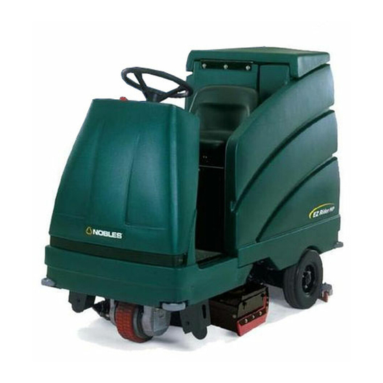
OPERATION MACHINE COMPONENTS A. Solution tank B. Tank Cover C. Vacuum fan inlet screen D. Recovery tank E. Steering wheel F. Operator seat G. Batteries H. Scrub head Side squeegee J. Rear wheel K. Rear squeegee L. Front wheel M. FaST PAK (Option) N. -
Page 9: Control Panel Symbols
OPERATION CONTROL PANEL SYMBOLS These symbols identify controls and displays on the machine: Horn ES (Extended Scrub) FaST Scrubbing Vacuum fan Recovery tank full Solution flow Battery charge Normal scrub Squeegee down Vacuum fan off EZ RidertHP 330780 (4- -04) -
Page 10: Controls And Instruments
OPERATION CONTROLS AND INSTRUMENTS A. Solution flow knob B. Horn button C. ES (Extended Scrub) Switch (Option) or FaST switch (Option) D. Brush down pressure switch E. Vacuum fan/squeegee switch F. Recovery tank full indicator G. Battery discharge indicator H. Hourmeter One step switch J. -
Page 11: Operation Of Controls
OPERATION OPERATION OF CONTROLS BRAKE PEDAL The brake pedal stops the machine. Stop: Take your foot off the directional pedal and allow it return to the Neutral position. Step on the brake pedal. PARKING BRAKE PEDAL The parking brake pedal sets the front wheel brake. -
Page 12: Steering Wheel
OPERATION Forward: Press the top of the directional pedal with the upper part of your foot. NOTE: The machine will not travel unless the operator is sitting in the operator’s seat. Reverse: Press the bottom of the directional pedal with the heel of your foot. When the directional pedal is placed into the reverse position, the rear squeegee will automatically raise. -
Page 13: On--Off Key Switch
OPERATION ON- -OFF KEY SWITCH The on- -off key switch controls the machine’s power with a key. FOR SAFETY: When starting machine, keep foot on brake and directional pedal in neutral. On: Turn the key all the way clockwise and release it to the on position. -
Page 14: Horn Button
OPERATION HORN BUTTON The horn button operates the horn. Sound: Press the button. SOLUTION FLOW KNOB The solution flow knob controls the amount of solution that flows to the floor while scrubbing. Increase solution flow: Turn the knob counterclockwise. Decrease solution flow: Turn the knob clockwise. NOTE: The machine is equipped with a solenoid valve that automatically stops the solution flow when the directional pedal is in the neutral... -
Page 15: Fast Switch
OPERATION FaST SWITCH The FaST switch enables the FaST (Foam Scrubbing Technology) system. When the FaST system is enabled, it is turned on and off with the One Step switch. On: Press the top of the FaST switch. Off: Press the bottom of the FaST switch. NOTE: The FaST system will not start until the directional pedal is pressed. -
Page 16: Brush Down Pressure Switch
OPERATION BRUSH DOWN PRESSURE SWITCH The brush down pressure switch controls the brush down pressure setting. The brush has two down pressure settings, standard and heavy. Travel speed and floor conditions will affect the scrubbing performance. Under normal conditions, the brush pressure should be set in the standard setting. -
Page 17: Recovery Tank Full Indicator
OPERATION RECOVERY TANK FULL INDICATOR The recovery tank full indicator light will illuminate when the recovery tank is full. NOTE: When the indicator illuminates, all scrubbing functions will shut off automatically. Empty the recovery tank when the recovery tank is full. Turn the machine power off and on again to restart the machine scrubbing functions. -
Page 18: Fuses
OPERATION FUSES The fuses are one-time protection devices designed to stop the flow of current in the event of a circuit overload. NOTE: Always replace the fuse with a fuse of the same amperage. The fuses are in--line and located near the two multi--pin connectors on the controller. -
Page 19: Operator Seat
OPERATION OPERATOR SEAT The operator seat is designed to be adjusted forward and backward. Adjust: Move the lever toward the center of the seat, slide the seat backward or forward to the desired position, and release the lever. NOTE: A seat switch is located under the operator seat. -
Page 20: Squeegee Wheel Cams
OPERATION SQUEEGEE WHEEL CAMS The squeegee wheel cams adjust the squeegee deflection along the entire length of the squeegee. There are wheel cams at either end of the squeegee. Increase deflection: Turn the cams counter-clockwise. Decrease deflection: Turn the cams clockwise. SQUEEGEE LEVELING KNOB The squeegee leveling knob adjusts the deflection at the ends of the squeegee. -
Page 21: How The Machine Works
NOTE: The amount and type of soilage play an important role in determining the type of brushes to be used. For specific recommendations, contact your Nobles representative. When finished scrubbing, clean the recovery tank. EZ RidertHP 330780 (12- -02) -
Page 22: Fast Scrubbing System
OPERATION FaST SCRUBBING SYSTEM Unlike conventional scrubbing, the FaST (Foam Scrubbing Technology) system operates by injecting the FaST PAK concentrate agent into the system with a small amount of water and compressed air. This mixture creates a large volume of expanded wet foam. The expanded foam mixture is then dispersed onto the floor while the machine is scrubbing. -
Page 23: Pre-Operation Checklist
OPERATION PRE-OPERATION CHECKLIST Perform the following steps before operating the machine: - Check under the machine for leaks. - Check the brakes and steering for proper operation. - Check for wire, string, or twine wrapped around the scrub brushes. - Check the squeegees for wear or damage. - Check the squeegee suction hose for obstructions. -
Page 24: Installing Fast Pak Agent
OPERATION INSTALLING FaST PAK AGENT NOTE: Machine must be equipped with the FaST system. 1. Remove the perforated knock--outs from the FaST PAK Floor Cleaning Concentrate carton. Do not remove the bag from the carton. Pull out the bag’s hose connector on the bottom of the bag and remove the hose cap from the connector. - Page 25 OPERATION 4. Make sure to connect the supply hose onto the hose storing plug when the supply hose is not connected to the FaST PAK. This will prevent the FaST solution system from drying out and clogging up the hose. 5.
-
Page 26: Starting The Machine
OPERATION STARTING THE MACHINE 1. You must be in the operator’s seat with the directional pedal in neutral, and your foot on the brake pedal or with the parking brake set. FOR SAFETY: When starting machine, keep foot on brake and directional pedal in neutral. -
Page 27: Filling The Tanks
OPERATION FILLING THE TANKS 1. Turn the machine power on. See the STARTING THE MACHINE section of the manual. FOR SAFETY: When starting machine, keep foot on brake and directional pedal in neutral. 2. Drive the machine to the tank filling site. 3. - Page 28 For specific recommendations, contact your Nobles representative. WARNING: Flammable materials can cause an explosion or fire. Do not use flammable materials in tank(s).
-
Page 29: Scrubbing And Brush Information
OPERATION SCRUBBING AND BRUSH INFORMATION Pick up oversized debris before cleaning. Pick up pieces of wire, string, twine, etc., which could become wrapped around the scrub brushes. Plan the scrubbing in advance. Try to arrange long runs with minimum stopping and starting. Do an entire floor or section at one time. - Page 30 OPERATION Heavy duty stripping pad -- This black pad is for stripping floors. Cuts through old heavy finishes easier, to prepare the floor for re-coating. Stripping pad -- This brown pad is for stripping floors. Quickly and easily cuts through old finish to prepare the floor for re-coating.
-
Page 31: Scrubbing
OPERATION SCRUBBING 1. Start the machine. See the STARTING THE MACHINE section of the manual. FOR SAFETY: When starting machine, keep foot on brake and directional pedal in neutral. 2. Drive the machine to the area to be cleaned. 3. Check the vacuum fan/squeegee switch and make sure it’s in the desired position. - Page 32 OPERATION 7. CONVENTIONAL SCRUBBING: Adjust the solution flow as needed. Increase flow: Turn the solution flow knob counterclockwise. Use this flow rate for rough floors and heavy or compacted dirt. NOTE: For machines equipped with cylindrical scrub heads, decrease solution flow rate when turning.
-
Page 33: Double Scrubbing
OPERATION DOUBLE SCRUBBING Double scrubbing is the process of making two or more scrubbing passes over a heavily soiled area. The first scrubbing pass is made with the rear squeegee up to allow the solution to soak into the floor. Double scrubbing can be performed using the FaST SCRUBBING SYSTEM or CONVENTIONAL SCRUBBING methods. -
Page 34: Stop Scrubbing
OPERATION STOP SCRUBBING 1. Press the bottom of the one step switch to stop the scrubbing operations. The scrub brushes will stop and the scrub head will raise. The solution flow will stop, and after a short delay, the rear squeegee will automatically raise and the scrubbing vacuum fan will stop. -
Page 35: Draining And Cleaning The Tanks
OPERATION DRAINING AND CLEANING THE TANKS When you are finished scrubbing, or when the recovery tank full indicator illuminates, the recovery tank should be drained and cleaned. The solution tank can then be filled again for additional scrubbing if necessary. If you used the machine in ES mode (option), the solution tank should also be drained and cleaned when you finish scrubbing. - Page 36 OPERATION Remove the drain hose cap while holding the hose up, then slowly lower the drain hose to the floor drain. Flush out the inside of the recovery tank with clean water. ES mode (option): Flush out the recovery tank with clean water. Rinse the ES filter at the bottom, and the float switch near the middle of the tank.
- Page 37 OPERATION ES mode (option): Remove the drain hose cap while holding the hose up, then slowly lower the drain hose to the floor drain. 11. ES mode (option): Lift the tank cover and flush out the solution tank with clean water. Rinse the filter at the bottom of the solution tank and the float switch near the middle of the tank.
- Page 38 OPERATION 13. Check the vacuum fan inlet filter daily. Clean inlet filter with a damp cloth or hose when dirty. Allow filter to dry completely before replacing it into machine. 14. Lower the tank cover. EZ RidertHP 330780 (12- -02)
- Page 39 OPERATION 15. Cylindrical scrub head: Lower the scrub head approximately 25mm (1 in). Remove the cotter pin that holds the side squeegee in place on the right hand side of the machine. Swing the squeegee away from the scrub head. 16.
-
Page 40: Stop The Machine
OPERATION STOP THE MACHINE 1. Stop scrubbing. See the STOP SCRUBBING section of the manual. 2. Take your foot off the directional pedal. Step on the brake predal to stop the machine. 3. Turn the machine power off. 4. Set the machine parking brake. FOR SAFETY: Before leaving or servicing machine, stop on level surface, set parking brake, turn off... -
Page 41: Post-Operation Checklist
OPERATION POST-OPERATION CHECKLIST - Check the battery charge level. NOTE: The reading on the battery discharge indicator may not be accurate when the machine is first powered on. Operate the machine a few minutes before reading the charge level of the batteries. -
Page 42: Options
OPERATION OPTIONS QUICK MOPt The QuickMop is a front end sweeping attachment that sweeps a clean path on the floor, as the machine scrubs the floor. 1. Drive the machine close to QuickMop attachment. 2. Set the machine parking brake and turn the machine power off. - Page 43 OPERATION 5. Pull the release lever to raise or lower each side of the QuickMop. 6. Turn the vacuum and brushes on, lower brushes and begin scrubbing. 7. Remove and refasten the QuickMop head covers with the easy to remove snaps. Remove the head covers to rotate, shake and clean at regular intervals.
-
Page 44: Machine Troubleshooting
Solution solenoid clogged or Clean or replace stuck Poor scrubbing performance Debris caught on scrub brushes Remove debris Improper detergent or brush Check with NOBLES used representative for advice Worn scrub brush(es) Replace scrub brush(es) Scrub brush motor fuse blown Replace fuse... - Page 45 OPERATION Problem Cause Remedy FaST System does not operate FaST switch is turned off Turn on the FaST switch. FaST circuit breaker tripped Determine cause and reset the 10A circuit breaker button Clogged FaST PAK supply hose Soak connector and hose in and/or connector warm water and clean FaST PAK carton is empty or not...
-
Page 46: Maintenance
MAINTENANCE MAINTENANCE 353813 EZ RidertHP 330780 (4- -04) -
Page 47: Maintenance Chart
1000 Hours Propelling motor Check motor brushes LUBRICANT/FLUID ..Distilled water . . . Special lubricant, Lubriplate EMB grease (NOBLES part no. 01433--1) ..SAE 90 weight gear lubricant EZ RidertHP 330780 (4- -04) -
Page 48: Lubrication
STEERING CASTER PIVOT BEARING The steering caster bearing is located on the floorplate. Lubricate with Lubriplate EMB grease (NOBLES part no. 01433--1) every 100 hours. REAR SQUEEGEE CASTERS The rear squeegee casters are located on the back side of the rear squeegee. Lubricate the... -
Page 49: Batteries
MAINTENANCE BATTERIES The batteries are designed to hold their power for long periods of time. The lifetime of the batteries is limited to number of charges the batteries receive. To get the most life from the batteries, recharge them immediately when the battery discharge indicator begins to blink. - Page 50 MAINTENANCE Using a hydrometer, measure the specific gravity to determine the charge level and condition of the batteries. If one or more of the battery cells test lower than the other battery cells (0.050 or more), the cell is damaged, shorted, or is near failure. Completely recharge the batteries, then retest them.
-
Page 51: Charging The Batteries
MAINTENANCE CHARGING THE BATTERIES 1. Drive the machine to a flat, dry surface. NOTE: Make sure the area is well ventilated. 2. Turn the machine power off and set the parking brake. FOR SAFETY: Before leaving or servicing machine, stop on level surface, set parking brake, turn off machine, and remove key. - Page 52 6. Plug the battery charger into the wall outlet. NOTE: If the red “ABNORMAL CYCLE” lamp lights when the NOBLES charger is plugged into a wall outlet, the charger cannot charge the battery and there is something wrong with the battery.
-
Page 53: Led Fault Code Display
Open) signals that the machine is on, and the operator is not in the operator’s seat. If the LED displays any diagnostic message other than messages 1, 4 or 10, contact your NOBLES service representative. DIAGNOSTIC MESSAGE High Battery Voltage... -
Page 54: Electric Motors
MAINTENANCE ELECTRIC MOTORS The carbon brushes on the vacuum fan motor should be inspected after every 500 hours of machine operation. The carbon brushes on the scrub brush motors and propelling motor should be inspected after every 1000 hours of machine operation. -
Page 55: Replacing The Disk Brushes Or Pads
MAINTENANCE REPLACING THE DISK BRUSHES OR PADS 1. Raise the scrub head. 2. Turn the machine power off and set the parking brake. FOR SAFETY: Before leaving or servicing machine, stop on level surface, set parking brake, turn off machine, and remove key. 3. - Page 56 MAINTENANCE 6. Press the brush/driver spring clip together with your thumb and index finger. The scrub brush/pad driver will drop off the drive hub. Pull the brush/driver out from under the scrub head. 7. PAD DRIVER ONLY: Turn the pad driver over to access the spring clip underneath.
- Page 57 MAINTENANCE 11. Place the new scrub brush/pad driver on the floor to the side of the scrub head. Push the brush under the scrub head. 12.Line up the brush /pad driver socket with the drive plug. 13.While pressing the brush spring clip together with your thumb and index finger, lift the scrub brush onto the drive plug.
-
Page 58: Cylindrical Brushes
MAINTENANCE CYLINDRICAL BRUSHES Check the brush taper and rotate the brushes from front-to-rear every 50 hours of machine operation for maximum brush life and best scrubbing performance. The cylindrical brushes should be replaced if large amounts of bristles are missing, or if the remaining bristle length is less than 10 mm (0.38 in). - Page 59 MAINTENANCE 5. Observe the shape of the brush patterns. If the brush patterns have parallel sides, the brushes do not need adjustment. 10355 If one, or both of the brush patterns are tapered, the brushes need adjustment to straighten the brush pattern. 10356 A.
- Page 60 MAINTENANCE C. Turn the idler shaft to raise or lower the end of the brush as needed to straighten the brush pattern. Tighten the mounting screw. D. Check the brush patterns again and readjust as necessary until both patterns are the same. 6.
-
Page 61: Replacing The Cylindrical Brushes
MAINTENANCE REPLACING THE CYLINDRICAL BRUSHES 1. Press the one step switch. When the scrub head is approximately 25 mm (1 in) from the floor, turn the machine power off. 2. Set the parking brake. FOR SAFETY: Before leaving or servicing machine, stop on level surface, set parking brake, turn off machine, and remove key. - Page 62 MAINTENANCE 6. Position the brush with the double row end towards you. Guide the new brush onto the drive hub. 7. Insert the Idler plug (on the inside of the idler door), into the brush. 8. Push down on the door to catch the door in the scrub head, then pull up on the door to latch it into the spring.
-
Page 63: Solution System
MAINTENANCE SOLUTION SYSTEM RECOVERY TANK The recovery tank holds recovered solution. Clean and drain the recovery tank after each use. The outside of the tank can be cleaned with vinyl cleaner. ES mode: Flush out the recovery tank with clean water after each use. -
Page 64: Fast System (Option)
MAINTENANCE FaST SYSTEM (Option) FaST SUPPLY HOSE CONNECTOR (Option) The FaST supply hose connector is located below the FaST PAK holder. Soak the connector in warm water if detergent buildup is visible. When a FaST PAK carton is not installed, store the supply hose connector on the storing plug to prevent the hose from clogging. -
Page 65: Rear Squeegee Assembly
MAINTENANCE REAR SQUEEGEE ASSEMBLY The squeegee assembly channels water into the vacuum fan suction. The front blade channels the water, and the rear blade wipes the floor. Check the squeegee blades for damage and wear daily. Rotate or replace either of the squeegee blades if the leading edge is torn or worn half-way through the thickness of the blade. -
Page 66: Replacing The Rear Squeegee Assembly
MAINTENANCE REPLACING THE REAR SQUEEGEE ASSEMBLY 1. Make sure the squeegee pivot is lowered. 2. Place the squeegee under the squeegee pivot. 3. Push the squeegee frame onto the squeegee pivot. 4. Tighten the mounting knobs. 5. Push the squeegee suction hose onto the squeegee fitting. -
Page 67: Adjusting Rear Squeegee Blade Deflection
MAINTENANCE ADJUSTING REAR SQUEEGEE BLADE DEFLECTION Deflection is the amount of curl the squeegee blade has when the machine moves forward while the squeegee lowered to the floor. The best deflection is when the squeegee wipes the floor just dry with a minimum amount of deflection. 1. -
Page 68: Adjusting The Squeegee Guide Roller
MAINTENANCE ADJUSTING THE SQUEEGEE GUIDE ROLLER The squeegee guide rollers are located on both ends of the rear squeege. The rollers guide the squeegee blade end along a wall. Loosen the nut at the top of the guide roller and move the roller in or out to adjust how close the end of the squeegee blade is to the wall. - Page 69 MAINTENANCE 4. Pull off the retaining band. 5. Pull off the rear squeegee blade. 6. Insert the rotated or new squeegee blade and then insert the retainer band. 7. Tighten the two retainer knobs until the ends of the front and rear squeegee blades touch. Do not over--tighten.
-
Page 70: Replacing Or Rotating The Front Squeegee Blade
MAINTENANCE REPLACING OR ROTATING THE FRONT SQUEEGEE BLADE 1. Make sure the squeegee is raised off the floor. 2. Turn the machine power off and set the parking brake if your machine has this option. FOR SAFETY: Before leaving or servicing machine, stop on level surface, and turn off machine. -
Page 71: Side Squeegee Blades
MAINTENANCE SIDE SQUEEGEE BLADES The side squeegees control water spray and channel water into the path of the rear squeegee. Check the side squeegees for damage and wear daily. Replace the side squeegee blades if they become damaged or lose their shape. Replace the squeegee deflectors if they become worn. -
Page 72: Belts And Chains
MAINTENANCE BELTS AND CHAINS BRUSH DRIVE BELTS The two brush drive belts are located on the cylindrical brush scrub head. The belts drive the cylindrical brushes. Proper new belt tension is a 3 mm (0.1 in) deflection from a force of 1.37 to 1.48 kg (3.0 to 3.26 lb) at the belt midpoint. -
Page 73: Skirts And Seals
MAINTENANCE SKIRTS AND SEALS SCRUB HEAD FLOOR SKIRTS The skirts are located in front and rear of the disc brush scrub heads. Check the skirts for damage and wear every 50 hours of operation. The skirts should clear the floor by 0 to 6 mm (0.0 to 0.3 in) when the scrub brushes are new, and the scrub head is down. -
Page 74: Brakes And Tires
MAINTENANCE BRAKES AND TIRES BRAKES The mechanical brake is located on the front wheel. The brake is operated by the brake pedal. Check the brake adjustment after every 200 hours of operation. If the brake does not respond well to pressure on the brake pedal, you may need to adjust the brake. -
Page 75: Tires
MAINTENANCE TIRES The machine has three tires: one in front, and two in the rear of the machine. All three tires are solid rubber. Check the tires for damage and wear after every 100 hours of operation. EZ RidertHP 330780 (12- -02) -
Page 76: Pushing, Towing, And Transporting The Machine
MAINTENANCE PUSHING, TOWING, AND TRANSPORTING THE MACHINE PUSHING OR TOWING THE MACHINE If the machine becomes disabled, it can be pushed from the front or rear, but only tow it from the front. Only push or tow the machine for a very short distance and do not exceed 3.2 kp/h (2 mph). - Page 77 MAINTENANCE 4. Position the machine onto the truck or trailer as far as possible. If the machine starts to veer off the centerline of the truck or trailer, stop and turn the steering wheel to center the machine. 5. Set the parking brake, lower the scrub head and block the machine tires.
-
Page 78: Machine Jacking
MAINTENANCE MACHINE JACKING Empty the recovery and solution tanks before jacking the machine. You can jack up the machine for service at the designated locations. Use a hoist or jack that will support the weight of the machine. Always stop the machine on a flat, level surface and block the tires before jacking up the machine. -
Page 79: Storage Information
MAINTENANCE STORAGE INFORMATION The following steps should be taken when storing the machine for extended periods of time. 1. Drain and clean the solution and recovery tanks. 2. Park the machine in a cool, dry area. 3. Remove the batteries, or charge them every three months. -
Page 80: Specifications
SPECIFICATIONS SPECIFICATIONS GENERAL MACHINE DIMENSIONS/CAPACITIES Item Dimension/capacity Length 1690 mm (66.5 in) Width (less squeegee) 820 mm (32.25 in) Width (with squeegee) 850 mm (33.5 in) Height 1372 mm (54 in) Disk brush diameter for 700 mm (28 in) scrub head 355 mm (14 in) Disk brush diameter for 810 mm (32 in) scrub head 400 mm (16 in) -
Page 81: Power Type
SPECIFICATIONS POWER TYPE Type Quantity Volts Ah Rating Weight Batteries 244 @ 20 hr rate 32 kg (72 lb) Type kW (hp) Scrub brush (disk) 0.50 (0.67) Electric Motors Scrub brush (Heavy Duty disk) 36 0.60 (0.80) Scrub brush (cylindrical) 0.56 (0.75) Vacuum fan 0.6 (0.8) -
Page 82: Machine Dimensions
SPECIFICATIONS 28 in scrub 820 mm 850 mm (32.25 in) (33.5 in) 1370 mm (54 in) 820 mm 1690 mm (32.25 in) (66.5 in) 353501 MACHINE DIMENSIONS EZ RidertHP 330780 (12- -02) -
Page 83: Index
INDEX Controls Brake pedal, 9 Adjustments Brush down pressure switch, 14 Rear squeegee blade deflection, 65 Circuit breakers, 16 Rear squeegee guide roller, 66 Directional pedal, 9 Service brakes, 72 ES switch (option), 12 Steering gear chain, 70 FaST switch, 13 Fuse, 16 Aisle turn, 78 Horn button, 12... - Page 84 INDEX FaST, 22 Machine components, 6 FaST Scrubbing System, 20 Machine dimensions, 80 FaST Supply Hose Connector, 62 Machine operation Double scrubbing, 31 FaST switch, 13 How the machine works, 19 FaST System, 62 Operation on inclines, 31 Specifications, 79 Post--operation checklist, 39 Pre--operation checklist, 21 FaST System Air Pump Filter, 62...
- Page 85 INDEX On-off key switch, 11 Safety Labels, 4 One step switch, 11 Precautions, 3 Operator responsibility, 5 Screen, FaST System Filter Screen, 62 Operator seat, 17 Scrub brush pressure, 14 Options, 40–41 Scrub brushes, 52–57 ES switch, 12 Adjusting cylindrical brush pattern, 56–58 FaST, 62 Brush pressure, 11, 14 FaST Scrubbing System, 20...
- Page 86 INDEX Specifications, 78–80 Battery chargers, 79 Vacuum fan inlet filter, 61 Electric motors, 79 FaST System, 79 Vacuum fan seal, 71 Machine capacities, 78 Vacuum fan/squeegee switch, 14 Machine dimensions, 78, 80 Machine performance, 78 Power type, 79 Tires, 79 Squeegee Adjusting deflection, 18 Adjusting guide rollers, 66...
Need help?
Do you have a question about the EZ Rider HP and is the answer not in the manual?
Questions and answers