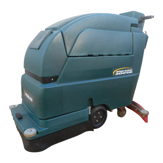
Nobles Speed Scrub 2001HD Operator And Parts Manual
Automatic scrubber
Hide thumbs
Also See for Speed Scrub 2001HD:
- Operator and parts manual (105 pages) ,
- Brochure (2 pages) ,
- Operator and parts manual (16 pages)
Table of Contents
Advertisement
Quick Links
Advertisement
Table of Contents

Subscribe to Our Youtube Channel
Related Manuals for Nobles Speed Scrub 2001HD


Summary of Contents for Nobles Speed Scrub 2001HD
- Page 1 Speed Scrub 2001HD Automatic Scrubber Model No.: Operator and Parts Manual 608311 608312 – Pac 609242 – Can. Pac NOBLES 12875 RANSOM STREET HOLLAND MI 49424 U.S.A. 608310 CUSTOMER SERVICE: 1-800-365-6625 FAX: 1–800–678–4240 Rev. 00 (09-99) Home Find... Go To..
-
Page 2: Table Of Contents
E1999 Tennant Company Printed in U.S.A The machine is maintained with manufacturer Nobles and Speed Scrub are registered United States trademarks of supplied or equivalent parts. Tennant Company. Specifications and parts are subject to change without notice. -
Page 3: Safety Precautions
OPERATION When servicing machine: SAFETY PRECAUTIONS – Avoid moving parts. Do not wear loose jackets, shirts, or sleeves. – Block machine tires before jacking This machine is intended for commercial use. It is machine up. suited to scrub hard floors in an indoor environment –... -
Page 4: Standard Machine Components
OPERATION STANDARD MACHINE COMPONENTS 1. Control Console 18. Solution Tank Drain Hose 2. Control Grips 19. Rear Fill Port 3. Main ON/OFF Switch 20. Squeegee Assembly 4. Vacuum ON/OFF Switch 21. Recovery Tank 5. Brush/Solution ON/OFF Switch 22. Recovery Tank Lid 6. -
Page 5: Control Panel Symbols
OPERATION CONTROL PANEL SYMBOLS Fast Speed Brush Motor Main Power Battery Charge Circuit Breaker Meter Slow Speed Vacuum Vacuum Brush Pressure Motor Cir- Meter Reverse cuit Brush Breaker Read Manual Main Power Squeegee Up Less Brush Before Operat- Circuit Pressure Breaker More Brush Squeegee... -
Page 6: Machine Installation
OPERATION 3. Carefully install batteries into battery tray at bottom of compartment and arrange battery posts MACHINE INSTALLATION as shown ( Figure 2 ). UNCRATING MACHINE (–) Carefully check carton for signs of damage. Report any damage at once to carrier. Check carton contents to ensure all accessories are included. - Page 7 OPERATION 3. Loosen two thumb knobs on squeegee assembly 3. Unfasten black latch at front of machine and hinge and slide squeegee into slots on squeegee mount open skirt housing to access motor hub ( Figure 7 ). bracket. Squeegee roller wheels should face outward ( Figure 4 ).
-
Page 8: Machine Operation
OPERATION NOTE: Always make sure pad driver and motor hub surfaces are clean before installing driver. Clean MACHINE OPERATION surfaces will ease pad driver removal later. 7. Close skirt housing and refasten latch. FOR SAFETY: Do not operate machine, unless operation manual is read and understood. - Page 9 OPERATION 3. Lower scrub head to floor. Turn main switch on 8. Once machine begins to move, check the needle and press and hold bottom half (+) of brush position of the brush pressure meter. Only operate pressure switch ( Figure 13 ). machine with needle in designated range per cleaning application.
- Page 10 OPERATION 10. Periodically check battery meter discharge level. When needle drops to the red zone, recharge WHILE OPERATING MACHINE batteries. FOR SAFETY: When using machine, go slow on ATTENTION: Do not continue to run machine inclines and slippery surfaces. when battery meter needle is in the red zone, battery damage will result.
-
Page 11: Draining Tanks
OPERATION 1. Pull clear hose off hose barb at rear of machine and drain solution into floor drain or bucket DRAINING TANKS ( Figure 21 ). Drive machine to floor drain and turn off machine. FOR SAFETY: Before leaving or servicing machine, stop on level surface and turn off machine. -
Page 12: Maintenance
OPERATION 2. Turn machine off. WARNING: To avoid an electrical hazard, FOR SAFETY: Before leaving or servicing charger MUST be grounded while in use to protect user from electric shock and serious injury. machine, stop on a level surface and turn off machine. - Page 13 OPERATION EVERY 250 HOURS OF OPERATION 1. Check drive and brush motor for carbon brush wear, replace brushes if worn to a length of 10mm (0.38 in) or less. 2. Check vacuum motor for carbon brush wear, replace brushes when worn to a length of 10mm (0.38 in) or less.
-
Page 14: Transporting Machine
OPERATION STORING MACHINE 1. Before storing machine, be certain to flush tanks and drain machine of all water. 2. Store machine in a dry area with squeegee removed and pad driver in the raised position. 3. Remove recovery lid to promote air circulation. 4. -
Page 15: Trouble Shooting
OPERATION TROUBLE SHOOTING PROBLEM CAUSE SOLUTION No power, nothing runs. Faulty main switch. Contact Service Center. Batteries need charging. See CHARGING BATTERIES. Faulty battery(s). Replace battery(s). Loose battery cable. Tighten loose cable. MAIN circuit breaker has tripped. Determine cause and reset breaker. Brush motor does not run. - Page 16 OPERATION TROUBLE SHOOTING –continued PROBLEM CAUSE SOLUTION Poor water pick up. Recovery tank is full. Empty recovery tank. Ball float shut–off screen inside recov- Remove screen and clean. ery tank is clogged. Squeegee is clogged with debris. Clean squeegee. Squeegee blades are worn. Replace squeegee blades.
-
Page 17: Specifications
OPERATION SPECIFICATIONS MODEL 2001HD LENGTH 1270mm (50 in) WIDTH 790mm (31 in) HEIGHT 990mm (39 in) WEIGHT 220kg (487 lbs) –w/ batteries 323kg (712 lbs) SOL./REC TANK CAPACITY 64L (17 gal) SPEED CONTROL Variable Fwd. / Fixed Rev. CLEANING SPEED (MAX) 1923.6m (20,000 sq. -
Page 18: Parts List
PARTS LIST SOLUTION TANK GROUP Speed Scrubt 2001HD (03–99) Home Find... Go To.. - Page 19 DESCRIPTION QTY. 608518 ASM., SOLUTION TANK COVER, 607433 TUBING, 3/4”IDX24” GREEN 630369 CLAMP 608284 COVER, TANK, GREEN 608451 DECAL, ”SPEED SCRUB 2001HD” 140706 RIVET, POP DCASTER, 4” 630002 230626 HINGE, COVER 140025 WASHER, FLAT 603233 DECAL, BATTERY RECHARGE 140333 WASHER, LOCK...
- Page 20 PARTS LIST RECOVERY TANK GROUP Speed Scrubt 2001HD (03–99) Home Find... Go To..
- Page 21 PARTS LIST RECOVERY TANK GROUP PART # DESCRIPTION QTY. PART # DESCRIPTION QTY. 701103 ASM.,STANDPIPE 140015 WASHER, LOCK DFLOAT, SHUT–OFF 180613 200 031 488 SCREW, M8X1.25X20MM DSEAT, NEOPRENE 230187 NIPPLE 0174..10 DGASKET DMOTOR, VAC 5.7 /3 STAGE 24 VDC 101714 130477 DCARBON BRUSH 2/PK 210240...
- Page 22 PARTS LIST DRIVE GROUP Speed Scrubt 2001HD (03–99) Home Find... Go To..
- Page 23 PARTS LIST DRIVE GROUP PART # DESCRIPTION QTY. PART # DESCRIPTION QTY. 600288 PLATE, BASE TRANSAXLE 578421 PIN, COTTER DTRANSAXLE 20” 140236 SCREW, 1/2–13X1 1/4 630126 DCAP 600292 BRACKET, ACTUATOR 630503 DCARBON BRUSH 140548 630504 DEND BELL, TRANSAXLE MOTOR 140314 CLAMP, INSULATED 3/4 ID 600606 DWHEEL, 8”...
- Page 24 PARTS LIST BRUSH GROUP Speed Scrubt 2001HD (03–99) Home Find... Go To..
- Page 25 PARTS LIST BRUSH GROUP PART # DESCRIPTION QTY. PART # DESCRIPTION QTY. DMOTOR, IMPERIAL 130491 140045 WASHER, .510X1.25X.06 FLAT DASM., BRUSH CARD 190741 602882 BUSHING, 1/2IDX5/8ODX5/16 DBRUSH, CARBON 190970 140516 NUT, 1/2–13 DKEY, 1/4X1 140632 140028 WASHER, FLAT DASM., GEAR BOX 630609 140017 WASHER, LOCK...
- Page 26 PARTS LIST BRUSH SKIRT GROUP Speed Scrubt 2001HD (03–99) Home Find... Go To..
- Page 27 PARTS LIST BRUSH SKIRT GROUP PART # DESCRIPTION QTY. PART # DESCRIPTION QTY. 608306 SKIRT, 2001HD LEFT SIDE, GREEN 140016 WASHER, LOCK 1/4 608308 SKIRT, 2001HD RIGHT SIDE, GREEN 600302 BRACKET, SKIRT MOUNT DSCREW 603154 140018 WASHER, LOCK #10 DWHEEL, RUBBER 630450 140011 WASHER, FLAT 3/16”...
- Page 28 PARTS LIST SOLUTION CONTROL GROUP Speed Scrubt 2001HD (03–99) Home Find... Go To..
- Page 29 PARTS LIST SOLUTION CONTROL GROUP PART # DESCRIPTION QTY. PART # DESCRIPTION QTY. 230661 PLATE, LOCK CONTROL HOUSING 140283 200 031 488 SCREW, M8X1.25X20MM 140011 WASHER, FLAT 140015 WASHER, LOCK 28303 HOSE BARB 140027 WASHER, FLAT 140310 CLAMP 600280.BK WELDMENT , DRAIN HOSE HANGER 607433 TUBING, 3/8”IDX1.67 230735...
- Page 30 PARTS LIST SQUEEGEE CONTROL GROUP PART # DESCRIPTION QTY. PART # DESCRIPTION QTY. DHOSE, VAC 1.5X30” W/CUFFS 160613 140272 SCREW, M6X1.0X16MM DCABLE, SQUEEGEE LIFT 630156 602880 PLATE, SQUEEGEE CABLE LINK 140501 200 031 496 SCREW, M08X35 140236 SCREW, 1/2–13X1 1/4 140015 WASHER, LOCK 140024...
- Page 31 PARTS LIST SQUEEGEE GROUP PART # DESCRIPTION QTY. PART # DESCRIPTION QTY. DASM., CURVED SQUEEGEE 603262 140221 SCREW, 5/16–18X1 1/4 DWHEEL 602958 WELDMENT , SQUEEGEE 630450 DGASKET 603260 140799 SCREW, 5/16–18X1 1/2 DPLATE, SQUEEGEE DROLLER SQUEEGEE 602962 700844 DBLADE, SQUEEGEE 603660 140015 WASHER, LOCK...
- Page 32 PARTS LIST CONSOLE GROUP Wire Harnesses Speed Scrubt 2001HD (09–99) Home Find... Go To..
- Page 33 PARTS LIST CONSOLE GROUP PART # DESCRIPTION QTY. PART # DESCRIPTION QTY. DGRIP, HANDLE TUBE 200823 140415 SPRING, LOCK PIN 27099 BUSHING 140155 BUSHING DKNOB, SPEED CONTROL 604402 HANDLE, TUBE 601110 DSPEED CONTROL, PMB, 55 AMP 630104 603007 BUSHING, SNAP 578 141 000 SCREW, M5X10MM 602886...
- Page 34 PARTS LIST ELECTRICAL / BATTERY GROUP Speed Scrubt 2001HD (03–99) Home Find... Go To..
-
Page 35: Options
PARTS LIST ELECTRICAL/BATTERY GROUP PART # DESCRIPTION QTY. PART # DESCRIPTION QTY. 602559 PANEL, CONTROL HOUSING 140829 SCREW, 6–32X1 222519 PLUG 140019 WASHER, LOCK DCONNECTOR, RED 50A W/O 069 764 626 PLUG, HOLE 012.7 27833 CONTACTS 130161 PLUG, DOME .850 578 321 000 SCREW, M6X16MM 130175... -
Page 36: Electrical Diagrams
ELECTRICAL DIAGRAMS WIRING DIAGRAM BATTERY AMMETER OPTIONAL ROLL EMERGENCY STOP SWITCH 4.7K ADJUSTABLE FORWARD BRUSH/ MAIN VACUUM DOWN SOLUTION ACTUATOR DIRECTION SWITCH OPTIONAL LOCKABLE KEY SWITCH REVERSE HARNESS CONNECTOR FLASHER ACTUATOR MOTOR MAIN VACUUM VACUUM/ MAIN DRIVE CIRCUIT CIRCUIT BREAKER BREAKER DRIVE MOTOR... - Page 37 ELECTRICAL DIAGRAMS LADDER DIAGRAM (2) 12 VOLT BATTERIES 24 VDC MASTER CIRCUIT BREAKER -34- -10- -14- -44- -50- -13- -BLK- -RED- MAIN -32- -GRN- -11- -BLK- SWITCH BATTERY VACUUM/DRIVE METER -24- -7- -BLK- CIRCUIT BREAKER MAIN -GRN- -6- RED -ORG- -12- -20- -RED- -60- -WHT- -21- -BLK-...
- Page 38 Speed Scrub 2001HD MAINTENANCE CHECK LIST WALL CHART To maintain excellent service of this machine, perform this simple check list as described below. Refer to your Operator’s Manual for further assistance. DESCRIPTION PROCEDURE DAILY DAILY n BATTERIES Recharge if needed. EVERY 4 HOURS EVERY 4 HOURS n PAD/BRUSH...
- Page 39 TROUBLE SHOOTING GUIDE - Continued PROBLEM CAUSE SOLUTION Vacuum motor does not run. Vacuum motor does not run. Faulty vacuum switch. Contact Service Center. Vacuum circuit breaker has tripped. Remove obstruction and reset breaker. Faulty vacuum motor or wiring. Contact Service Center. Carbon brushes worn.
Need help?
Do you have a question about the Speed Scrub 2001HD and is the answer not in the manual?
Questions and answers