Hitachi WH 14DBL Technical Data And Service Manual
Cordless impact driver
Hide thumbs
Also See for WH 14DBL:
- Instruction manual (60 pages) ,
- Handling instructions manual (50 pages)
Table of Contents
Advertisement
Quick Links
Download this manual
See also:
Instruction Manual
Advertisement
Table of Contents

Related Manuals for Hitachi WH 14DBL


Summary of Contents for Hitachi WH 14DBL
- Page 1 MODEL WH 14DBL CORDLESS IMPACT DRIVER WH 14DBL LIST No.: G893 Feb. 2008...
- Page 2 REMARK: Throughout this TECHNICAL DATA AND SERVICE MANUAL, a symbol(s) is(are) used in the place of company name(s) and model name(s) of our competitor(s). The symbol(s) utilized here is(are) as follows: Competitors Symbols Utilized Company Name Model Name MAKITA BTD130F...
-
Page 3: Table Of Contents
9. OTHER PRECAUTIONS-------------------------------------------------------------------------------------------------- 20 10. REPAIR GUIDE------------------------------------------------------------------------------------------------------------ 21 10-1. Precautions in Disassembly and Reassembly ------------------------------------------------------------ 21 10-2. Precautions in Disassembly and Reassembly of Battery Charger ----------------------------------- 33 11. STANDARD REPAIR TIME (UNIT) SCHEDULES --------------------------------------------------------------- 34 Assembly Diagram for WH 14DBL... -
Page 4: Product Name
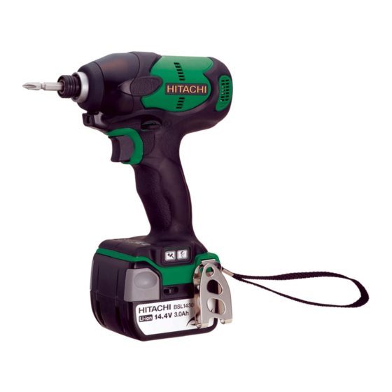
Hitachi Cordless Impact Driver, Model WH 14DBL 2. MARKETING OBJECTIVE The new cordless impact driver Model WH 14DBL is equipped with the newly developed and highly efficient brushless motor. Features of the Model WH 14DBL include the following. • 1.3 times higher performance thanks to the highly efficient brushless motor (compared with the Model WH 14DSL) •... -
Page 5: Selling Points
• The Model WH 14DBL is equipped with the overdischarge and overcurrent protection circuit to prevent overdischarge (overuse) of the battery. -
Page 6: Selling Point Descriptions
The newly developed brushless motor does not require conventional carbon brushes and commutators. Therefore, the Model WH 14DBL can operate at a low current without friction and electric loss. Its working performance per charge is 1.3 times higher than the Model WH 14DSL. - Page 7 (3) Tightening mode selector function The Model WH 14DBL can be used for wide range of applications such as heavy load works requiring high tightening torque and delicate works thanks to the single/continuous selector switch and the 4-step high/low selector switch.
- Page 8 (b) Tightening time comparison The following graph shows the time required for driving a wood screw (5.3 mm in diameter and 120 mm in length) into lauan. The Model WH 14DBL can drive long screws into hard workpieces at high speed.
- Page 9 (5) Remaining battery indicator The Model WH 14DBL is equipped with the remaining battery indicator that is the same as the well-reputed indicator of the current Model WH 14DSL. The battery remaining power can be checked just by pressing the remaining battery indicator switch.
-
Page 10: Specifications
6. SPECIFICATIONS 6-1. Specifications Model WH 14DBL Small screw* 4 to 8 mm Capacity Ordinary bolt M5 to M14 High-strength bolt M5 to M12 Tightening torque 150 N m (1,530 kgf cm, 1,330 in-lbs.) • • Tip condition 6.35 mm (1/4”) hex. bit shank... -
Page 11: Optional Accessories
*1: M3 (1/8") tapping screws and wood screws are the smallest screws that can be tightened. *2: The maximum tightening torque is based on tightening an M14 high-strength bolt (strength grade 12.9) for 3 seconds with a socket adapter and a hexagonal socket (entire length 40 mm). *3: The main body weight does not include the standard accessories and the hook, but includes the battery. -
Page 12: Comparisons With Similar Products
7. COMPARISONS WITH SIMILAR PRODUCTS 7-1. Specification Comparisons Maker HITACHI Item Model WH 14DBL WH 14DSL WH 14DL M 4 to M 8 M 4 to M 8 M 4 to M 10 M 4 to M 8 Small screw (5/32"... -
Page 13: Tightening Torque
7-2. Tightening Torque 7-2-1. Comparison of tightening torque in each mode The data below shows the tightening torque obtained in each mode of the Model WH 14DBL. Please note that the data are intended for reference purposes only because the actual tightening torque may vary depending on hardness of workpieces, diameter of thread, ambient temperature, characteristics of the battery, etc. - Page 14 7-2-2. Screw diameter and appropriate tightening torque Generally speaking, the appropriate tightening torque for a screw can be determined by the strength grade of the screw and the material tightened. Tables 1 and 2, and Fig. 4 below list data relative to the strength grade of various screws and the appropriate tightening torque.
- Page 15 7-2-3. Tightening torque characteristics The graph below shows the relationship between tightening time and tightening torque according to types of bolts. The data below are intended for reference purposes only because actual tightening torque may vary depending on tightening conditions. NOTE: •...
-
Page 16: Tightening Time
7-3. Tightening Time The performance of the Model WH 14DBL is superior to the competitors thanks to the large hammer and the optimized impact timing. A tightening time comparison is shown below. The data below are intended for reference purposes only because actual tightening time may vary depending on hardness of the workpiece, ambient temperature, characteristics of the battery, etc. -
Page 17: Number Of Screws Or Bolts Driven
The table below shows a comparison of the number of screws or bolts that can be driven per battery charge by the Models WH 14DBL, WH 14DSL and WH 14DL and P. Please note that the data below are intended for reference purposes only because the number of screws that can be driven per charge may vary depending on screw tightening conditions, screw size, ambient temperature and charging capacity of the battery. -
Page 18: Precautions In Sales Promotion
8. PRECAUTIONS IN SALES PROMOTION 8-1. Safety Instructions In the interest of promoting the safest and most efficient use of the Model WH 14DBL cordless impact driver by all of our customers, it is very important that at the time of sale the salesperson... - Page 19 Incorrect parts replacement and/or wiring will cause malfunctions which could result in fire or other hazards. Instruct the customers to bring the Model WH 14DBL to an authorized service center in the event repair or replacement is necessary.
- Page 20 For the U.S.A. and Canada CAUTION • For safe operation, see Instruction Manual. • Charge HITACHI rechargeable batteries Types BSL 14 and BSL 18 series. Other types of batteries may burst causing personal injury and damage. • Charge between 32 °F and 104 °F. Rest 15 minutes between the charging of batteries.
-
Page 21: Tightening Torque Inspection Prior To Operation
8-2. Tightening Torque Inspection Prior to Operation As described and shown in Para.7-3-3, the output tightening torque of the Model WH 14DBL exceeds the rated tightening torque of certain bolts and screws. Accordingly, if the tightening time is prolonged for such bolts and screws, it could cause damage to their threads or, in the worst case, cause them to be sheared off. -
Page 22: Precautions For Efficient Use Of Charger
(4) Different material to be tightened When a bolt is tightened into a soft material such as aluminum, plastic, wood, etc., the tightening torque is considerably low in comparison with the tightening torque required for tightening a bolt into a hard material such as steel. (5) Different tightening conditions The tightening torque may vary in accordance with the bolt torque coefficients (depending on manufacturing processes, and specified by bolt manufacturers), bolt grade and bolt length... -
Page 23: Other Precautions
(4) Precaution against impact and water Do not give a strong impact on the Model WH 14DBL by dropping or do not wet the Model WH 14DBL with water because precision components are incorporated in it. Otherwise, a malfunction will occur. -
Page 24: Repair Guide
10-1. Precautions in Disassembly and Reassembly The [Bold] numbers in the description below correspond to the item numbers in the Parts List and the exploded assembly diagram of the Model WH 14DBL. 10-1-1. Disassembly (1) Removal of guide sleeve (D) By following the procedure shown in Figs. - Page 25 (3) Remove the M4 Truss Hd. Screw (Black) [37] and Hook (A) [38]. By removing Hook (A) [38], housing (A).(B) set can be disassembled easily. (4) Remove the nine Tapping Screws (W/Flange) D4 x 20 (Black) [30] to remove housing (B) from the Housing (A).(B) Set [29].
- Page 26 (7) Disassembly of the controller. stator ass'y and the switch Remove the terminal of the internal wires (red and black) of the Controller. Stator Ass'y [44] and the two Machine Screws (W/Sp. Washer) M3 x 5 [36] from the DC-Speed Control Switch [34].
- Page 27 Controller. Stator Ass'y [44] Stator Inner Cover (D) [25] Rotor [27] Fig. 9 Ring Gear (E) [20] (9) Removal of the rotor and inner cover (D) O-ring (S-42) [21] Support Inner Cover (D) [25] without Washer (E) [22] contacting the fan of the Rotor [27]. Push down the pinion tip of the Rotor [27] to Damper [24] remove the Rotor [27].
- Page 28 10-1-2. Reassembly Reassembly can be accomplished by following the disassembly procedures in reverse. However, special attention should be given to the following items. (1) Reassembly of the power supply unit (a) Be sure to follow the wiring diagram for proper wiring when replacing the DC-Speed Control Switch [34] and the Controller.
- Page 29 Put the internal wires between the ribs of housing (A). Internal wire (Black) Internal wire (Red) Fig. 12 (2) Reassembly of the hammer assembly (a) Put Washer (S) [15] onto the shaft of Spindle (D) [18] and mount Hammer (F) [11] containing the twenty-eight Steel Balls D3.175 [12], Washer (J) [13] and Hammer Spring (D) [14] to Spindle (D) [18].
- Page 30 Inner cover rib Hammer case rib Fig. 13 (3) Reassembly of housing (A). (B) set (a) Apply silicone rubber (THREEBOND 1211) to the diagonally shaded areas in Fig. 14 before mounting the parts to housing (A). (b) Mount a unit of the hammer assembly, Hammer Case [7], Inner Cover (D) [25] (including the Rotor [27]), Controller.
- Page 31 Dust Cover [26] Rotor [27] Stator Concave portion of the Protrusion of the stator Dust Cover [26] Be sure to mount the Hammer Case [7] to housing (A) securely. Hammer Case [7] Mount the LED light to this position. Protrusion (for locking) Bring the protrusion (for locking) of the Hammer Case [7] into contact with this portion of housing (A).
- Page 32 Packing [41] Boss of the Strap (Black) [42] Packing [41] Lock Nut M4 (Black) [40] Fig. 16 (4) Mounting the exterior parts (a) Cover the assembled housing with the Front Cover (Black) [6] and Front Cap (F) [5]. Check that the board in the LED light does not protrude from the LED holder. Then engage the protrusion of the Hammer Case [7] with the protrusion of the LED holder.
- Page 33 ATTOLUB MS No. 2 • Pinion tooth flanks of the Rotor [27], Ring Gear (E) [20] and Idle Gear Set (2 pcs.) [17] HITACHI MOTOR GREASE No. 29 • Two Steel Balls D3.5 [8] • Sliding section between Anvil (D) [9] and Guide Sleeve (D) [4] MOLUB-ALLOY 777-1 •...
- Page 34 (8) Checking after reassembly Check the following after reassembly. (a) Check that the switching operation is smooth and the Model WH 14DBL can start, stop, change speed and perform forward/reverse operation reliably. (b) Check that the rotational speed changes in 4 steps each time the high/low selector switch is pressed.
- Page 35 (10) Wiring diagram Wiring diagram Push the internal wire in the groove. Controller. Stator Ass'y [44] Push flat cable (A) in the groove. Push flat cable (A) and the internal wire in the groove. Push flat cable (A) in the groove. DC Speed Control Switch [34] Do not catch flat cable (B) with Push the internal wire in the groove.
-
Page 36: Precautions In Disassembly And Reassembly Of Battery Charger
10-2. Precautions in Disassembly and Reassembly of Battery Charger Refer to the Technical Data and Service Manual for precautions in disassembly and reassembly of the Model UC 18YRSL battery charger. -33-... -
Page 37: Standard Repair Time (Unit) Schedules
11. STANDARD REPAIR TIME (UNIT) SCHEDULES Variable MODEL Fixed Work Flow WH 14DBL Hook (A) Housing (A).(B) Set Inner Cover Rotor Controller. Stator Ass’y DC Speed Control Switch General Assembly Hammer Hammer (F) Guide Spring Case Steel Ball Anvil (C) - Page 38 LIST NO. G893 CORDLESS IMPACT DRIVER Model WH 14DBL (E1) 504 505 506...
- Page 39 PARTS WH 14DBL ITEM CODE NO. DESCRIPTION REMARKS USED 315-984 RETAINING RING 315-983 WASHER (D) 321-657 GUIDE SPRING (D) 322-717 GUIDE SLEEVE (D) 327-766 FRONT CAP (F) 328-650 FRONT COVER (BLACK) 327-003 HAMMER CASE 319-535 STEEL BALL D3.5 (10 PCS.)
- Page 40 STANDARD ACCESSORIES WH 14DBL ITEM CODE NO. DESCRIPTION REMARKS USED CHARGER (MODEL UC 18YRSL) 329-440 CASE ASS'Y INCLUD. 503-506 324-093 LATCH (DARK GRAY) 324-096 KNOB (L) DARK GRAY 324-090 HANDLE (DARK GRAY) 324-099 KNOB (R) DARK GRAY OPTIONAL ACCESSORIES ITEM CODE NO.
- Page 41 WH 14DBL ITEM CODE NO. DESCRIPTION REMARKS USED - 4 - Printed in Japan 2 - 08 *ALTERNATIVE PARTS (080206N)
Need help?
Do you have a question about the WH 14DBL and is the answer not in the manual?
Questions and answers