Table of Contents
Advertisement
Advertisement
Table of Contents
Troubleshooting

Related Manuals for Advance acoustic Warrior ST


Summary of Contents for Advance acoustic Warrior ST
-
Page 1: Service Manual
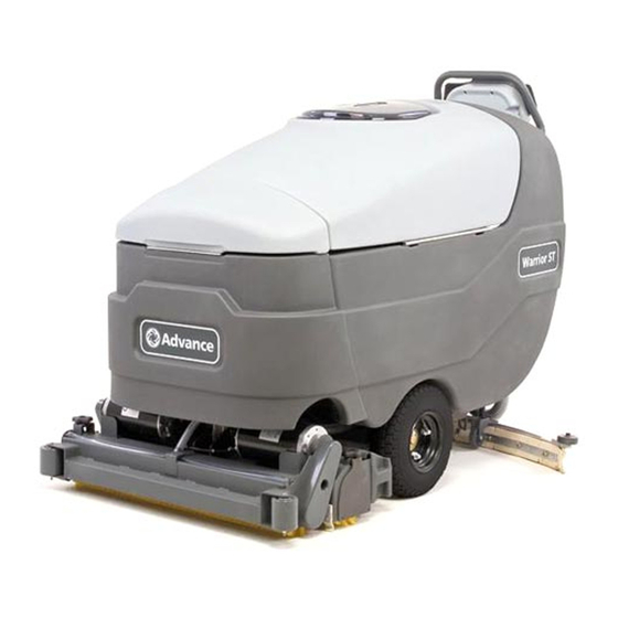
Warrior ST, Warrior ™ ™ Service Manual Advance Models: 56315036(28D), 56315037(32D), 56315038(28C) 56315039(32C-C), 56315040(X28D-C), 56315041(X32D-C) 56315538(28D-C), 56315539(32D-C), 56315540(28C-C) 56315541(X28C-C), 56315542(X32C-C) 9/05 revised 9/08 FORM NO. 56043103... -
Page 3: Table Of Contents
TABLE OF CONTENTS INTRODUCTION ......................................2 CAUTIONS AND WARNINGS ..................................3 SPECIFICATIONS & MAINTENANCE............................... 4-6 PM CHECKLIST ......................................7 KNOW YOUR MACHINE ..................................8-13 SOLUTION SYSTEM ..................................... 14-21 FUNCTIONAL OVERVIEW ..................................14 CIRCUIT OVERVIEW SOLUTION AUTO MODE ..........................15-16 SOLUTION SYSTEM MAINTENANCE ..............................16 TROUBLESHOOTING GUIDE ................................ -
Page 4: Introduction
INTRODUCTION This manual will help you get the most from your Advance automatic scrubber. Read it thoroughly before servicing the machine. Note: Bold numbers and letters in parentheses indicate an item illustrated on pages 8-10. PARTS AND SERVICE Repairs, when required, should be performed by your Authorized Advance Service Center, who employs factory trained service personnel, and maintains an inventory of Advance original replacement parts and accessories. -
Page 5: Cautions And Warnings
CAUTIONS AND WARNINGS SYMBOLS Advance uses the symbols below to signal potentially dangerous conditions. Read this information carefully and take the necessary steps to protect personnel and property. DANGER! Is used to warn of immediate hazards that will cause severe personal injury or death. WARNING! Is used to call attention to a situation that could cause severe personal injury. -
Page 6: Specifications & Maintenance
TECHNICAL SPECIFICATIONS revised 5/08 4 - FORM NO. 56043103 - Warrior ST, Warrior ™ ™... - Page 7 TECHNICAL SPECIFICATIONS FORM NO. 56043103 - Warrior ST, Warrior AXP - 5 ™ ™...
-
Page 8: Maintenance Schedule
MAINTENANCE SCHEDULE Maintenance intervals given are for average operating conditions. Machines used in severe operational environments may require service more often. MAINTENANCE ITEM Daily Weekly Monthly Yearly Charge Batteries Check/Clean Tanks & Hoses (clean recovery tank switches & vacuum inlet screen) Check/Clean/Rotate the Brushes/Pads Check/Clean the Squeegee Clean Hopper on Cylindrical System... -
Page 9: Pm Checklist
Warrior ST, Warrior AXP Cylindrical and Disc PM Checklist Defect Codes Customer needs adjustment binding Address dirty or contaminated damaged, bent or torn City leaks missing Model Serial Hours W worn out Does OPERATIONAL INSPECTION ITEMS Defect Codes (circle) Work... -
Page 10: Know Your Machine
KNOW YOUR MACHINE As you read this manual, you will occasionally run across a bold number or letter in parentheses - example: (2). These numbers refer to an item shown on these pages unless otherwise noted. Refer back to these pages whenever necessary to pinpoint the location of an item mentioned in the text. Note: Refer to the service manual for detailed explanations of each item illustrated on the next 4 pages. - Page 11 KNOW YOUR MACHINE Solution Drain Hose / Level Indicator Recovery Tank Drain Hose Squeegee Raise / Lower Lever Debris Hopper (Cylindrical Models Only) Battery Pack Connector (non onboard charger models only) Idler Assembly (Cylindrical Models Only) Recovery Hose Solution Manifold (Cylindrical Models Only) Wheel Drive Circuit Breaker Extended Scrub Filter (Optional) Control Circuit Circuit Breaker...
- Page 12 CONTROL PANEL – AXP Key Switch (Main Power) Solution Switch Vacuum Switch Display Panel D1 Solution Flow Indicator D2 Fault Indicator D3 Hour Meter D4 AXP Indicator D5 Battery Indicator D6 Scrub Pressure Indicator D7 Recovery Tank FULL Indicator D8 Battery Low Indicator Wand Switch (Dealer Installed Option) Detergent System (AXP models only) Extended Scrub System (Dealer Installed Option)
- Page 13 CONTROL PANEL – STANDARD Key Switch (Main Power) Display Panel Solution Switch D1 Solution Flow Indicator Vacuum Switch D2 Fault Indicator D1 Solution Flow Indicator D3 Hour Meter Wand Switch (Dealer Installed Option) D5 Battery Indicator Extended Scrub System (Dealer Installed Option) D6 Scrub Pressure Indicator Scrub OFF D7 Recovery Tank FULL Indicator...
- Page 14 KNOW YOUR MACHINE FUNCTIONAL DESCRIPTION OF CONTROL PANEL: The controls on the Warrior were designed with one touch operation in mind. For single pass scrubbing the user can simply depress one switch and all systems on the machine will be ready to go. For most single-pass scrubbing operations, the operator should only need to use the middle switches on the control panel.
-
Page 15: Know Your Machine
KNOW YOUR MACHINE DESCRIPTION OF INDICATORS ON THE CONTROL PANEL: In general, the following guidelines apply to the control panel indicators: A fl ashing green or yellow indicator means that a fault has occurred in the particular system. An example of this would be an over-current fault. A yellow indicator means that the particular function has been enabled but is not currently on. -
Page 16: Solution System
SOLUTION SYSTEM FUNCTIONAL OVERVIEW See Figure 1. The Warrior™ models have a solution tank fi ll capacity of 30 gallons (113.5 Liters). All models use one right rear tank fi ll opening, which offers ease of fi lling. Plumbed into the manual solution shutoff valve outlet is a serviceable Solution Filter (C), to keep debris from entering the solenoid valve (all models) and solution pump (AXP™... -
Page 17: Circuit Overview Solution Auto Mode
SOLUTION SYSTEM CIRCUIT OVERVIEW SOLUTION AUTO MODE (SOLENOID VALVE CIRCUIT) APPLIES TO AXP™ MODELS See Figure 2. + (Positive) circuit input starts with: • A closed S3 key switch will direct the needed positive voltage (BRN wires) to the L1 solenoid coil and A1 control board terminal #J1-13. - (Negative) circuit input starts with: •... -
Page 18: Solution System Maintenance
APPLIES TO STANDARD (NON AXP™) MODELS The Warrior ST machines do not use a solution pump. The (3) solution fl ow volumes are managed by the A1 control board’s negative voltage output from the terminal J1-11 Red/Grn wire. This input from A1 to the solution solenoid also requires negative voltage from Pin 6 - Brake on the speed controller (A2) to J1-5 – For/Rev. on A1 (Red/Blk wire). - Page 19 SOLUTION SYSTEM TROUBLESHOOTING GUIDE ELECTRICAL Possible Symptoms 1-No solution fl ow while in the scrub auto solution mode. 2-Solution Pump will not operate: SYMPTOM ONE Note: Activate the Service Test Mode Program. See optional program section for instructions. All testing will be performed in the Service Test Mode Program. FORM NO.
- Page 20 SOLUTION SYSTEM TROUBLESHOOTING GUIDE ELECTRICAL (CONTINUED) SYMPTOM TWO Note: Activate the Service Test Mode Program. See optional program section for instructions. All testing will be performed in the Service Test Mode Program. 18 - FORM NO. 56043103 - Warrior ST, Warrior ™...
-
Page 21: Solution Solenoid Valve Removal, Disassembly And Cleaning (Axp™)
SOLUTION SYSTEM SOLENOID VALVE REMOVAL (AXP™) Drain the solution tank or turn the solution fi lter ball valve to the off position to prevent solution loss. Lower the deck and disconnect the battery supply to the machine. Remove the front Nose Cone from the machine by fi rmly grasping the lower part and lifting straight up. See Figure 3. -
Page 22: Solution Solenoid Valve Removal, Disassembly And Cleaning (Standard)
SOLUTION SYSTEM SOLENOID VALVE REMOVAL (STANDARD) Drain the solution tank or turn the solution fi lter ball valve to the off position to prevent solution loss. Disconnect the battery supply to the machine. See Figure 4. Unplug the L1 solenoid valve wire assembly connection from the machine harness. Unscrew the inlet Hose Clamps (K) that secure the hoses to the valve body. -
Page 23: Solution Filter And Ball Valve Removal
SOLUTION SYSTEM SOLUTION FILTER AND BALL VALVE REMOVAL Drain the solution tank using the solution drain hose (B). See Figure 5. Loosen the (2) Hose Clamps (R) and pry off the inlet Solution Hose (S) and Solution Hose (T). Remove the (2) Hose Clamps (U) that secure the Filter / Valve Assembly to the chassis and remove the assembly from the machine. FIGURE 5 AXP MODELS ONLY SOLUTION PUMP REMOVAL (AXP™) -
Page 24: Scrub System
SCRUB SYSTEM FUNCTIONAL OVERVIEW • Disk Brush System Overview See Figure 2. The disk models use a disk type scrub system powered by (2) 3/4 hp motor gearbox assemblies. • Cylindrical Brush System Overview See Figure 4. The cylindrical models use two cylindrical brushes that counter rotate to sweep up light debris and scrub at the same time. Each scrub brush is powered on opposing ends by 3/4 HP permanent magnet motors attached to separate poly-V belt/pulley drives. - Page 25 SCRUB SYSTEM • Scrub Brush Removal Function (Continued / Disc only) • Control and Load circuit detail. A closed S3 key switch supplies the needed positive voltage to the K1 brush solenoid coil, A1 control board (J1-13) Brn wire and K3 brush remove coil relay (Part of A1 Control Board).
-
Page 26: Scrub Brush Deck Removal (Disc)
SCRUB SYSTEM SCRUB BRUSH DECK REMOVAL (DISC) Lower the scrub deck with brushes (pads) installed. Turn the key switch off and disconnect the battery pack. Lift up and remove cover and nose cone, from front of machine. See Figure 2. Separate the solution system water line located on top of the scrub deck. Loosen the Hose Clamp (A) and separate the hoses. Unplug both of the brush motor wiring harnesses (B). - Page 27 SCRUB SYSTEM FIGURE 2 FORM NO. 56043103 - Warrior ST, Warrior AXP - 25 ™ ™...
-
Page 28: Scrub Brush Motor/Gearbox Removal (Disc)
SCRUB SYSTEM SCRUB BRUSH MOTOR/GEARBOX REMOVAL (DISC) Follow the steps in the Scrub Brush Deck Removal (Disc) section. Turn the brush deck on its back. Remove the scrub brushes from the brush holders. If removing both motor/gearboxes mark the location of the holders and motors to the brush deck for proper re-assembly. - Page 29 NOTES FORM NO. 56043103 - Warrior ST, Warrior AXP - 27 ™ ™...
-
Page 30: Scrub Brush Deck Removal (Cylindrical)
SCRUB SYSTEM SCRUB BRUSH DECK REMOVAL (CYLINDRICAL) Lower the scrub deck with brushes installed. Turn the key switch off and disconnect the battery pack. Lift up and remove cover and nose cone, from front of machine. See Figure 4. Disconnect the Solution Hose (O) from the scrub deck. Unplug both brush motors wire assembles. -
Page 31: Scrub System
SCRUB SYSTEM FIGURE 4 FORM NO. 56043103 - Warrior ST, Warrior AXP - 29 ™ ™... -
Page 32: Recovery System
RECOVERY SYSTEM FUNCTIONAL OVERVIEW Vacuum / Recovery System General Dirt and water are lifted off the fl oor into the 30 Gallon (114 liter) recovery tank by airfl ow, created by a 3-Stage 36V vacuum motor. The wastewater and air enter the vacuum system at the squeegee tool, through small openings (notches) located in the front squeegee blade. -
Page 33: Vacuum Motor Control Circuit Overview (Auto Mode)
RECOVERY SYSTEM VACUUM MOTOR CONTROL CIRCUIT OVERVIEW (AUTO MODE) See Figure 2. + (Positive) Circuit input starts with: • A closed S3 key switch supplies the needed positive voltage to the K2 vacuum solenoid coil and the A1 control board J1-13 (Brn wire). Note: The A1 control board scrub-on button must also be depressed (enabled). -
Page 34: Vacuum/Recovery System Maintenance Checklist
RECOVERY SYSTEM VACUUM / RECOVERY SYSTEM SERVICE MAINTENANCE CHECKLIST Whenever there is a vacuum problem, it’s best to check over the entire system. Use the checklist below as a guide, to thoroughly check the vacuum system. □ Inspect and clean the vacuum motor fl oat switch. Note that on current models, if the switch is closed (tipped up) the vacuum motor will not operate. □... -
Page 35: Maintenance Of Recovery Tank Float Switches
RECOVERY SYSTEM MAINTENANCE OF RECOVERY TANK FLOAT SWITCHES If the recovery tank fl oat switch(es) become dirty it can impair their proper operation. A dirty vacuum shutoff switch can cause the vacuum motor to not function at all or to not shut off when the tank is full. Dirty extended scrub system switches can prevent the optional extended scrub system from functioning properly. If daily rinsing of the recovery tank does not suffi... -
Page 36: Maintenance Of Vacuum Motor Inlet Screen
RECOVERY SYSTEM MAINTENANCE OF VACUUM MOTOR INLET SCREEN The Vacuum Motor Inlet Screen (4) should be cleaned on a daily basis. DO NOT run water down the screen in an attempt to clean it. If you do this you will be running water directly into the vacuum motor. -
Page 37: Vacuum Motor Removal
RECOVERY SYSTEM VACUUM MOTOR REMOVAL Drain the recovery tank using the drain hose. Turn the key off and disconnect the battery pack Swing open the recovery tank and disconnect the vacuum motor harness connector. See Figure 5. Remove the vacuum motor Shroud Cover (A) secured to the bottom of the recovery tank (qty 4 screws). Loosen the exhaust hose clamp and remove Hose (B) from the vacuum motor discharge tube and completely remove the Vacuum Motor (C) from its mount cavity. -
Page 38: Recovery Tank Removal
RECOVERY SYSTEM RECOVERY TANK REMOVAL Follow steps 1-5 in the Vacuum Motor Removal section. Disconnect Recovery Tank fl oat switch(es). Note: Disconnect any other options installed on the tank. See Figure 6. Remove the Screw (F) and Tank Cable (G) and allow the tank to swing down to the side of the battery compartment box. Remove the Recovery Tank Drain Hose (H). -
Page 39: Squeegee System
SQUEEGEE SYSTEM SQUEEGEE LIFT LINKAGE ADJUSTMENT See “Know Your Machine”. The squeegee pick-up tool is raised and lowered manually by a rear control panel mounted Lever (17). Squeegee Lift Lever Adjustment The squeegee tool’s storage and operating positions are adjustable. To adjust: Lower the squeegee assembly to the fl... -
Page 40: Servicing The Squeegee
SQUEEGEE SYSTEM SERVICING THE SQUEEGEE If the squeegee leaves narrow streaks or water, the blades may be dirty or damaged. Remove the squeegee, rinse it under warm water and inspect the blades. Reverse or replace the blades if they are cut, torn, wavy or worn. To Reverse or Replace the Rear Squeegee Wiping Blade... -
Page 41: Squeegee Mount Assembly Removal
SQUEEGEE SYSTEM SQUEEGEE MOUNT ASSEMBLY REMOVAL See Figure 3. Disconnect Squeegee Hose (19) and remove the Squeegee Assembly (13) from the machine. Lower the Squeegee Lever (17) and disconnect the Squeegee Lift Cable (C) from the squeegee mount bracket. Remove Screw (D) and slide the Squeegee Mount Assembly (E) away from the chassis. FIGURE 3 FORM NO. -
Page 42: Caster Wheel Removal
SQUEEGEE SYSTEM CASTER WHEEL REMOVAL WARNING! Disconnect the battery pack connector before servicing machine. WARNING! Never work under machine without safety stands or blocking to support the machine. Drain both the solution and recovery tanks. Remove the squeegee assembly and have the scrub deck in the up (stored) position with the scrub brushes installed. -
Page 43: General Functional Overview
WHEEL DRIVE SYSTEM GENERAL FUNCTIONAL OVERVIEW See Figures 1 and 2. A 375 watt (.5 HP) permanent magnet (36V) motor transaxle (M1) is used for the wheel drive on all machines. A Curtis PMC solid state speed controller (A2) regulates the variable speed and Fwd/Rev wheel drive motor functions. Location of the controller is in the rear handle housing electrical compartment (accessible by removing the 4 screws securing the rear electrical panel). - Page 44 WHEEL DRIVE SYSTEM FIGURE 2 FUSE,150A. BATTERY Partial A1 Control Board CIRCUIT BREAKER, 5AMP SW, SPST KEY (OPTIONAL) EM BRAKE RED/BLK 36V ONLY YEL/BLU WHT/YEL CIRCUIT BREAKER, 30AMP B+ B- SPEED CONTROLLER PIN 14 - BRAKE (+) POT. 5K OHM (1228 FOR 36V) ORN/BLU THROTTLE...
-
Page 45: Wheel Drive System
WHEEL DRIVE SYSTEM R2 Voltage Values R1 Voltage Values FIGURE 3 0V = Minimum Speed 0 – 2.5V Forward 5V = Maximum Speed 2.5V – 5V Reverse WHEEL DRIVE SYSTEM R1 Throttle 5K Ohms A1 Speed Control Pin Connection POT WIPER POT HIGH STATUS BRAKE... -
Page 46: Wheel Drive Troubleshooting Guide
WHEEL DRIVE SYSTEM WHEEL DRIVE TROUBLESHOOTING GUIDE Problem Possible Cause • Wheel Drive Motor Circuit Breaker (F3) tripped (reset 30A circuit breaker) • Wheel drive motor will not run in forward and reverse. • Control Circuit Circuit Breaker (F2) tripped (reset circuit breaker) •... -
Page 47: Drive Motor Transaxle Removal
WHEEL DRIVE SYSTEM DRIVE MOTOR TRANSAXLE REMOVAL WARNING! Disconnect the battery pack before servicing machine. WARNING! Never work under machine without safety stands or blocking to support the machine. Drain both the solution and recovery tanks and remove the squeegee. Remove the Scrub deck by following the Scrub Deck Removal instructions in this manual. -
Page 48: Drive Motor Transaxle Removal
WHEEL DRIVE SYSTEM DRIVE MOTOR TRANSAXLE REMOVAL CONTINUED See Figure 5. Jack the front of the machine from this location until the drive wheels are approximately 1” off the ground. Remove the (6) Locknuts (A) and then remove the (2) Drive Wheels (B) from the transaxle. Disconnect the drive motor wiring connector. -
Page 49: Drive Wheel Removal
WHEEL DRIVE SYSTEM DRIVE WHEEL REMOVAL WARNING! Disconnect the battery pack connector before servicing machine. WARNING! Never work under machine without safety stands or blocking to support the machine. Remove the squeegee and place wood blocking in front and rear of the opposite drive wheel that you are removing to prevent the machine from rolling. Using a scissors jack, raise the machine until the wheel is off the ground. -
Page 50: (5K) Potentiometer (R1) Testing And Removal
WHEEL DRIVE SYSTEM (5K) POTENTIOMETER (R1) TESTING AND REMOVAL WARNING! Disconnect batteries at the battery pack disconnect before servicing. Testing the 5KDirectional/Throttle Potentiometer R1 Note: The potentiometer (pot) doesn’t have to be removed from its housing mount to test. See Figure 7. Remove the front Drive Paddle Cover (G) from the Rear Housing (H) held together with (4) (I) Screws. Note the cover will have the speed limiting Pot (R2) mounted to it, observe the (3) wires and separate them to complete the removal of the cover. -
Page 51: (100K) Potentiometer (R2) Testing And Removal
WHEEL DRIVE SYSTEM (5K) POTENTIOMETER (R1) INSTALLATION AND ADJUSTMENT (CONTINUED) Reconnect the ohmmeter test leads to the pot wiper and low terminal connections and adjust (turn the pot) to obtain half of pot’s total resistance. This will accurately set the true neutral drive paddle operator position. Tighten the anchor nut secure. -
Page 52: Electrical System
ELECTRICAL SYSTEM BATTERIES If your machine shipped with batteries installed do the following: • Check that the batteries are connected to the machine (14 or 18). • Turn ON the Key Switch (A) and check the Battery Indicator (D5 or J1). If the gauge is completely fi lled or the green light is ON, the batteries are ready for use. If the gauge is less than full or the green light is OFF, the batteries should be charged before use. -
Page 53: Description Of The Low-Voltage Cutout Feature
ELECTRICAL SYSTEM SPECIFIC WET CELL BATTERY INFORMATION Wet Cell Battery specifi cations - Use a combination of multiple 2-volt cell units to construct a 36 Volt DC battery pack system. - Advance recommended battery pack capacity is a 305 AH @ 20 Hour Rate deep cycle battery system. Note: The battery pack must fi t the battery compartment size listed in Specifi... -
Page 54: Battery Charging, Maintenance And Testing
ELECTRICAL SYSTEM CHARGING WET BATTERIES AXP - Charge the batteries each time the machine is used or when the Battery Indicator (D5) is reading less than full. Standard - Charge the batteries each time the machine is used or when the Battery Indicator (J1) is fl ashing RED. WARNING! Do not fi... -
Page 55: Battery Testing
ELECTRICAL SYSTEM BATTERY MAINTENANCE WET CELL BATTERIES Proper maintenance of electric vehicle batteries can greatly extend their life. Well-maintained batteries may last up to 3 years, but failure after 1 year is common if maintenance has been poor. There are 3 simple rules for good battery maintenance: •... -
Page 56: Actuator Drive Nut Adjustment
ELECTRICAL SYSTEM ACTUATOR DRIVE NUT ADJUSTMENT This manual section explains the steps for adjusting the drive nut (spring housing) setting for all the models’ scrub brush lift actuator motor. Reference the chart below to fi nd the IN & OUT dimensional specifi cation for an actuator motor needing adjustment. Part # Actuator Motor Spring Housing IN Position... - Page 57 FIGURE 4 FORM NO. 56043103 - Warrior ST, Warrior AXP - 55 ™ ™...
-
Page 58: Curtis Controller
ELECTRICAL SYSTEM CURTIS CONTROLLER DIAGNOSTICS: Diagnostics Method A: Uses the machine’s control display LED panel and wand switch indicator. FUNCTION OF THE SPEED CONTROLLER STATUS LIGHT AND DISPLAY The Curtis 1228- (36V) speed control will output a fault code if there is a problem associated with the speed control and wheel drive system. See Figure 5. If a speed control fault occurs, the display panel (D) on AXP™... - Page 59 ELECTRICAL SYSTEM FIGURE 5 AXP MODELS revised 5/08 FORM NO. 56043103 - Warrior ST, Warrior AXP - 57 ™ ™...
-
Page 60: Speed Control Programming Options
ELECTRICAL SYSTEM STATUS LED FAULT CODES (TABLE 1) STATUS LIGHT EXPLANATION POSSIBLE CAUSE CODE DISPLAY over-/under-temperature cutback 1. Temperature >92°C or < -25°C. 2. Excessive load on vehicle 3. Operation in extreme environments. 4. Electromagnetic brake not releasing. 0 00 throttle fault 1. -
Page 61: Installation Checkout For The Curtis Speed Controller
ELECTRICAL SYSTEM INSTALLATION CHECKOUT FOR THE CURTIS SPEED CONTROLLER SAFETY! The 1228 controller is inherently a high power device. When working around any battery powered vehicle, proper safety precautions should be taken. These include, but are not limited to: proper training, wearing eye protection, avoiding loose clothing and jewelry, and using insulated wrenches. -
Page 62: Functional Overview Of Main Control Board
ELECTRICAL SYSTEM FUNCTIONAL OVERVIEW OF MAIN CONTROL BOARD The primary function of the main control board A1 is to position the scrubbing brush(s) with respect to the fl oor surface using a lift actuator motor to maintain the correct brush pressure and current draw of the brush motor(s). When the scrub ON switch is depressed this will lower the scrub deck to the operating position and by activating the drive paddle start the brush motors. -
Page 63: Main Controller Error Codes
1. Check for wiring problems (short) on all three coil circuits and repair wiring. 2. Check resistance on all three solenoid coils. The nominal resistance specs on the solenoids are as follows: K1 – Brush Motor Solenoid Coil, Warrior ST, Ametek brand - 98 ohms. ®... -
Page 64: Main Controller Diagnostic Service Test Mode
ELECTRICAL SYSTEM SERVICE TEST MODE: To assist in the troubleshooting and servicing of the electrical system and related components on the Warrior™ scrubbers, a special test mode that allows independent control of the various outputs and monitoring of the various inputs has been incorporated. To enter the service test mode perform the following step: Turn the main power Key Switch (A) to the off position. - Page 65 ELECTRICAL SYSTEM FIGURE 6 AXP Models. revised 5/08 FORM NO. 56043103 - Warrior ST, Warrior AXP - 63 ™ ™...
-
Page 66: Output Controls
ELECTRICAL SYSTEM BATTERY STATUS DISPLAY: The display (D or R) will show the battery voltage. This display is accurate to within +/- 0.15 volts. Therefore, the voltage displayed may not correlate precisely to a high-accuracy, calibrated voltmeter. OUTPUT CONTROLS: The control panel switches are used to control various output functions of the main control unit. Below is a list of each switch and the function it controls. Following the list is a detailed description of each function. - Page 67 ELECTRICAL SYSTEM OUTPUT CONTROLS (CONTINUED): Scrub On Switch (I): This switch is used to control the output to the scrub deck lift actuator. Pressing and releasing this switch will cycle the actuator output through 4 states. These are: 1 – Output off, direction = up 2 –...
-
Page 68: Output Controls
ELECTRICAL SYSTEM OUTPUT CONTROLS (CONTINUED): Solution Switch (B): This switch is used to toggle the state of the solution pump and/or solution solenoid. Pressing and releasing this switch will alternately turn the solution solenoid (L1) on and off (ST models), or turn the solution pump (M7) and solution solenoid (L1) on and off (AXP™ models). The indicator provides the following status information: Off - Solution output is off. -
Page 69: Main Control Programming Options
ELECTRICAL SYSTEM MAIN CONTROL PROGRAMMING OPTIONS Selection of Low-voltage Cutout Threshold: FACTORY DEFAULT: 30.96V (STANDARD) The Warrior™ is equipped with a low-voltage cutout feature to prevent over-discharging the batteries. This feature will automatically shut down the scrub system when the battery voltage falls to the selected threshold. The cutout level is adjustable. The Standard setting is 30.96 volts (1.72 volts per cell) and the alternate (Gel Cell) setting is 32.58 volts (1.81 volts per cell). - Page 70 ELECTRICAL SYSTEM MAIN CONTROL PROGRAMMING OPTIONS (CONTINUED) Restoring the scrub pressures to factory default settings: If it is desired to restore the scrub pressures to factory default setting, perform the following steps: Turn the main power key switch to the off position. Press and hold the scrub on switch.
- Page 71 ELECTRICAL SYSTEM MAIN CONTROL PROGRAMMING OPTIONS (CONTINUED) Turning Fault Detection On or Off: FACTORY DEFAULT: ON Normally, the main control unit will perform checks of the electrical system during operation. If a fault occurs in a particular system, that system (and possibly others) will be shut down.
- Page 72 ELECTRICAL SYSTEM MAIN CONTROL PROGRAMMING OPTIONS (CONTINUED) Regular Scrub Setting Adjustment: FACTORY DEFAULT: SCRUB PRESSURE =1, SOLUTION = ONE BAR(#1), CHEMICAL = 0 (IF AVAILABLE). The regular scrub pressure, solution rate and chemical rate can be programmed depending on its application where high solution rate is need with regular scrub pressure or low solution rate with heavy scrub pressure.
- Page 73 ELECTRICAL SYSTEM MAIN CONTROL PROGRAMMING OPTIONS (CONTINUED) Heavy Scrub Setting Adjustment: FACTORY DEFAULT: SCRUB PRESSURE =2, SOLUTION = TWO BARS(#2), CHEMICAL = 0 (IF AVAILABLE). The heavy scrub pressure, solution rate and chemical rate can be programmed depending on its application where high solution rate is need with regular scrub pressure or low solution rate with heavy scrub pressure.
- Page 74 ELECTRICAL SYSTEM MAIN CONTROL PROGRAMMING OPTIONS (CONTINUED) ST models: Turn the main power key switch to the off position. Press and hold in the scrub on switch and recycle switch. While holding both switches, turn the key switch to the on position. Continue to hold both switches until the recycle indicator and regular and heavy scrub indicators turn green.
-
Page 75: Electrical System
ELECTRICAL SYSTEM MAIN CONTROL PROGRAMMING OPTIONS (CONTINUED) LCD Style Selection (Warrior™ AXP): FACTORY DEFAULT: RECTANGULAR SHAPE WITH THREE BARS LCD graphic style can be programmed to different style. There are two different styles and to change LCD graphic style, perform the following steps: Turn the main power key switch to the off position. - Page 76 THIS PAGE IS INTENTIONALLY BLANK 74 - FORM NO. 56043103 - Warrior ST, Warrior ™ ™...
-
Page 77: Electrical Component Location
ELECTRICAL SYSTEM COMPONENT LOCATION Item Description Control Board Speed Control Battery (Not Shown) Fuse, 150 Amp Circuit Breaker, 5 Amp Circuit Breaker, 30 Amp Contactor, Brush Motor Contactor, Vac Motor Solenoid, Solution Solenoid, Recycle Solution (Optional) Motor, Wheel Drive Motor, Left Brush Motor, Right Brush Motor, Vac Motor, Brush Actuator... -
Page 78: Wiring Diagram
ELECTRICAL SYSTEM (OPTIONAL) ONBOARD BATTERY (OPTIONAL) WIRING DIAGRAM / SCHEMATIC CHARGER NOTE: CONNECT GRN WIRE TO F2 AND DISCONNECT RED WIRE FROM F2 FOR CHARGER OPTION CHEMICAL RATIO SENSOR INTERLOCK Item Description SUPPLY BLK/WHT CIRCUIT BREAKER, 5 AMP CIRCUIT BREAKER, 5 AMP Control Board OUTPUT Speed Control... - Page 79 ELECTRICAL SYSTEM CONTROL BOARD VIO/BLK 18-1 BLK 18-6 ORN/RED 18-1 BLK 18-5 BRN 16-1 BLU/BLK 22-1 YEL/VIO 18-1 WHT/GRA 18-1 BLK/YEL 18-1 RED/BLK 18-1 ORN 18-1 GRA/WHT 18-1 POT. 5K OHM THROTTLE RED/GRN 18-1 ORN/BLU 22-1 BLK 18-4 BRN/BLK 18-1 YEL/GRN 18-1 RED/WHT 18-1 WHT/GRN 18-1...
-
Page 80: Appendix
APPENDIX DETERGENT (AXP) SYSTEM PLUMBING SCHEMATIC Item Description Solution Tank Shut Off Valve Inline Solution Filter Solution Pump Check Valve Detergent Pump Reducer Tee Reducer Coupler Solution Solenoid Valve Detergent Tank Reducer Coupler Solution Manifold (Cylindrical Models) 78 - FORM NO. 56043103 - Warrior ST, Warrior™... -
Page 81: Extended Scrub System Plumbing Schematic
Extended Scrub Filter Extended Scrub Stop Switch Extended Scrub Start Switch Vacuum Shut Off Switch Extended Scrub Pump Solution Pump (not used on the Warrior ST models) Reducer Coupler Solution Solenoid Valve Reducer Coupler Extended Scrub Solenoid Valve Solution Manifold (Cylindrical Models) Service Note: After each use, drain and rinse the recovery tank thoroughly and then fi... -
Page 82: Detergent (Axp) System Preparation And Use
APPENDIX DETERGENT (AXP™) SYSTEM PREPARATION AND USE COMMON INSTRUCTIONS: REFILLABLE CARTRIDGE SPECIFIC INSTRUCTIONS: The system should be purged of previous detergent when switching to a different detergent. Fill the detergent cartridge with a maximum of 1.25 gallons (4.73 Liters) of detergent. SERVICE NOTE: Move machine over fl... -
Page 83: Switch Sequences For Main Controller Programming Options
Refer to the Electrical System/Main Control Programming Options section in this manual for complete instructions on how to access and use the main controller programming options. Switches Pressed to Access Option Programming Option Warrior with AXP™ Warrior ST Enter Service Test Mode Wand Switch (E) Wand Switch (E) Low-voltage Cut-out Threshold... -
Page 84: Main Controller I/O Tables
APPENDIX MAIN CONTROLLER I/O TABLES revised 8/08 82 - FORM NO. 56043103 - Warrior ST, Warrior ™ ™... - Page 85 APPENDIX MAIN CONTROLLER I/O TABLES (CONTINUED) revised 5/08 FORM NO. 56043103 - Warrior ST, Warrior AXP - 83 ™ ™...
Need help?
Do you have a question about the Warrior ST and is the answer not in the manual?
Questions and answers