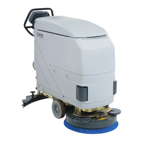
Advance acoustic BA 5321 Service Manual
Hide thumbs
Also See for BA 5321:
- Instructions for use manual (32 pages) ,
- Instructions for use manual (6 pages)

Related Manuals for Advance acoustic BA 5321


Summary of Contents for Advance acoustic BA 5321
- Page 1 BA 5321/D - BA 6124D SERVICE MANUAL Advance Models: 08838130 - 08838135 from serial number 1640309 908 7014 020 08603992(1)2003-06...
- Page 2 Nilfisk-Advance, Inc. 14600 21st Avenue North Plymouth, MN, 55447-3408 www.nilfisk-advance.com Phone: 800-989-2235 Fax: 800-989-6566 ©2003 Nilfisk-Advance, Inc., Plymouth, MN 55447-3408 Printed in Italy...
-
Page 3: Table Of Contents
BRUSH MOTOR REPLACEMENT (BA 5321/D Only) BRUSH MOTOR REPLACEMENT (BA 6124D Only) BRUSH MOTOR BRUSHES (OR CARBON BRUSHES) CHECK AND REPLACEMENT (BA 5321/D Only) 22 BRUSH MOTOR BRUSHES (OR CARBON BRUSHES) CHECK AND REPLACEMENT (BA 6124D Only) BRUSH BELT CHECK (BA 6124D Only) - Page 4 BATTERY MAINTENANCE AND RECHARGING TRACTION ELECTRONIC BOARD REPLACEMENT SERVICE ELECTRONIC BOARD REPLACEMENT ELECTRONIC BOARD CONTROLLING THE BRUSH MOTOR OPERATION CHECK AND REPLACEMENT (BA 6124D Only)) TROUBLESHOOTING COMPONENT LAYOUT BA 5321 WIRING DIAGRAM WIRING DIAGRAM BA 5321D WIRING DIAGRAM BA 6124D 08603992(1)2003-06...
-
Page 5: General Information
OTHER AVAILABLE MANUALS The following manuals are available by Advance Literature Service Department: – BA 5321/D - BA 6124D Part List – Form Number 08812649 – BA 5321/D - BA 6124D Instructions for Use - Form Number 08812648 08603992(1)2003-06... -
Page 6: Safety - Accident Prevention
SERVICE MANUAL GENERAL INFORMATION SAFETY - ACCIDENT PREVENTION Advance uses the following symbols to indicate potentially dangerous situations. Always read carefully this information and take the necessary precautions to protect people and objects. DANGER ! Indicates the risk of being injured or the risk of death. WARNING ! Indicates the risk of being injured. -
Page 7: Technical Data
SERVICE MANUAL GENERAL INFORMATION TECHNICAL DATA Dimensions BA 5321/D - BA 6124D BA 5321/D BA 6124D Suction width 770 mm (30 in) 812 mm (32 in) Sweeping width 530 mm (20.8 in) 610 mm (24 in) Machine length 1330 mm (52 in) 1311 mm (51.61 in) - Page 8 SERVICE MANUAL GENERAL INFORMATION BA 5321/D 1330 BA 6124D 1311 S300455 Size in mm 08603992(1)2003-06...
-
Page 9: Maintenance
SERVICE MANUAL GENERAL INFORMATION MAINTENANCE SCHEDULED MAINTENANCE The machine proper and safe operation is granted by a careful and constant maintenance. See GENERAL INFORMATION and SAFETY - ACCIDENT PREVENTION The following table sums up the scheduled maintenance. The indicated periods can be subjected to variations according to working conditions. -
Page 10: Machine Nomenclature
Traction switch (*) Suction motor Acoustic insulation assembly Brush motor Brushes (BA 6124D only) Traction adjusting handles (BA 5321/D only) Brush motor electronic board and protective cover (BA 6124D Brush (BA 5321/D) only) Integrated battery charger Inspection cover for brush rotation belt (BA 6124D only) - Page 11 SERVICE MANUAL GENERAL INFORMATION MACHINE NOMENCLATURE (CONTINUES) S300163 08603992(1)2003-06...
-
Page 12: Detergent Supply System
SERVICE MANUAL DETERGENT SUPPLY SYSTEM DETERGENT TANK AND SUPPLY SYSTEM CLEANING DETERGENT SUPPLY SYSTEM Empty the detergent tank (14) through the pipe (26). Take the detergent flow control lever (6) in wide-open position, then activate the machine until the detergent inside the machine is exhausted. -
Page 13: Solenoid Valve And Detergent Flow Tap Replacement
SERVICE MANUAL DETERGENT SUPPLY SYSTEM SOLENOID VALVE AND DETERGENT FLOW TAP REPLACEMENT Drive the machine on a level ground. Turn the switch key (2) to OFF position. If there is recovery water in the tank (11) remove it through the pipe (25). If there is detergent in the tank (14) remove it through the pipe (26). -
Page 14: Detergent Flow Cable And Control Lever Replacement
SERVICE MANUAL DETERGENT SUPPLY SYSTEM DETERGENT FLOW CABLE AND CONTROL LEVER REPLACEMENT Drive the machine on a level ground. Turn the switch key (2) to OFF position. Operating under the machine left side, loosen the sheath (D) fixing clamp (C) and disconnect the cable (A) from the tap lever (B). -
Page 15: Troubleshooting
SERVICE MANUAL DETERGENT SUPPLY SYSTEM TROUBLESHOOTING SMALL AMOUNT OF THE DETERGENT OR NO DETERGENT REACHES THE BRUSH Possible cause: The brush switch (3) is not in ON position or it is broken (position it to ON or repair/replace it). The detergent filter is obstructed/dirty (clean it). The detergent flow control lever does not control the related tap anymore (check the control lever cable, from the lever to the tap). -
Page 16: Sweeping System
SERVICE MANUAL SWEEPING SYSTEM BRUSH MOTOR ELECTRICAL INPUT CHECK (BA 5321/D Only) SWEEPING SYSTEM WARNING! This procedure must be performed by qualified personnel only. REMARK: the motor installed on the machine can either be a BOSCH (shown in the figure below) or a AMER;... -
Page 17: Brush Motor Electrical Input Check (Ba 6124D Only)
SERVICE MANUAL SWEEPING SYSTEM BRUSH MOTOR ELECTRICAL INPUT CHECK (BA 6124D Only) WARNING ! This procedure must be performed by qualified personnel only. Remove the brushes (41). Drive the machine on a level ground. Turn the switch key (2) to OFF position. If there is recovery water in the tank (11) remove it through the pipe (25). - Page 18 SERVICE MANUAL SWEEPING SYSTEM BRUSH MOTOR ELECTRICAL INPUT CHECK (BA 6124D Only) (Continues) Figure 3 S300457 Figure 4 S300423 08603992(1)2003-06...
-
Page 19: Brush Motor Replacement (Ba 5321/D Only)
SERVICE MANUAL SWEEPING SYSTEM BRUSH MOTOR REPLACEMENT (BA 5321/D Only) REMARK: the motor installed on the machine can either be a BOSCH or a AMER. The following procedure refers to the BOSCH motor only. Remove the brush (18). Drive the machine on a level ground. - Page 20 SERVICE MANUAL SWEEPING SYSTEM BRUSH MOTOR REPLACEMENT (BA 5321/D Only) REMARK: the motor installed on the machine can either be a BOSCH or a AMER. The following procedure refers to the AMER motor only. Remove the brush (18). Drive the machine on a level ground.
-
Page 21: Brush Motor Replacement (Ba 6124D Only)
SERVICE MANUAL SWEEPING SYSTEM BRUSH MOTOR REPLACEMENT (BA 6124D Only) Remove the brushes (41). Drive the machine on a level ground. Turn the switch key (2) to OFF position. If there is recovery water in the tank (11) remove it through the pipe (25). If there is detergent in the tank (14) remove it through the pipe (26). - Page 22 SERVICE MANUAL SWEEPING SYSTEM BRUSH MOTOR REPLACEMENT (BA 6124D Only) (continues) Figure 8 S300458 08603992(1)2003-06...
- Page 23 SERVICE MANUAL SWEEPING SYSTEM BRUSH MOTOR REPLACEMENT (BA 6124D Only) (continues) Figure 9 S300426 Figure 10 S300427 08603992(1)2003-06...
-
Page 24: Brush Motor Brushes (Or Carbon Brushes) Check And Replacement (Ba 5321/D Only)
SERVICE MANUAL SWEEPING SYSTEM BRUSH MOTOR BRUSHES (OR CARBON BRUSHES) CHECK AND REPLACEMENT (BA 5321/D Only) REMARK: The motor installed on the machine can either be a BOSCH or a AMER. The following procedure refers to the AMER motor only. -
Page 25: Brush Motor Brushes (Or Carbon Brushes) Check And Replacement (Ba 6124D Only)
SERVICE MANUAL SWEEPING SYSTEM BRUSH MOTOR BRUSHES (OR CARBON BRUSHES) CHECK AND REPLACEMENT (BA 6124D Only) Drive the machine on a level ground. Turn the switch key (2) to OFF position. If there is recovery water in the tank (11) remove it through the pipe (25). If there is detergent in the tank (14) remove it through the pipe (26). -
Page 26: Brush Belt Check (Ba 6124D Only)
SERVICE MANUAL SWEEPING SYSTEM BRUSH BELT CHECK (BA 6124D Only) Drive the machine on a level ground. Turn the switch key (2) to OFF position. If there is recovery water in the tank (11) remove it through the pipe (25). If there is detergent in the tank (14) remove it through the pipe (26). -
Page 27: Brush Belt Replacement And Head Bearings Check (Ba 6124D Only)
SERVICE MANUAL SWEEPING SYSTEM BRUSH BELT REPLACEMENT AND HEAD BEARINGS CHECK (BA 6124D Only) Drive the machine on a level ground. Turn the switch key (2) to OFF position. If there is recovery water in the tank (11) remove it through the pipe (25). If there is detergent in the tank (14) remove it through the pipe (26). - Page 28 SERVICE MANUAL SWEEPING SYSTEM BRUSH BELT REPLACEMENT AND HEAD BEARINGS CHECK (BA 6124D Only) (Continues) Figure 14 S300462 08603992(1)2003-06...
- Page 29 SERVICE MANUAL SWEEPING SYSTEM BRUSH BELT REPLACEMENT AND HEAD BEARINGS CHECK (BA 6124D Only) (Continues) Figure 15 S300432 Figure 16 S300432 08603992(1)2003-06...
-
Page 30: Brush Reduction Unit Replacement (Ba 5321/D Only)
SERVICE MANUAL SWEEPING SYSTEM BRUSH REDUCTION UNIT REPLACEMENT (BA 5321/D Only) REMARK: The motor installed on the machine can either be a BOSCH or a AMER. The following procedure refers to the BOSCH motor only. Remove the brush (18). Drive the machine on a level ground. - Page 31 SERVICE MANUAL SWEEPING SYSTEM BRUSH REDUCTION UNIT REPLACEMENT (BA 5321/D Only) (Continues) Figure 19 S300463 08603992(1)2003-06...
- Page 32 SERVICE MANUAL SWEEPING SYSTEM BRUSH REDUCTION UNIT REPLACEMENT (BA 5321D Only) REMARK: The motor installed on the machine can either be a BOSCH or a AMER. The following procedure refers to the AMER motor only. Remove the brush (18). Drive the machine on a level ground. Turn the switch key (2) to OFF position.
- Page 33 SERVICE MANUAL SWEEPING SYSTEM BRUSH REDUCTION UNIT REPLACEMENT (BA 5321/D Only) (Continues) Figure 20 S300435 Figure 21 S300173 08603992(1)2003-06...
- Page 34 SERVICE MANUAL SWEEPING SYSTEM BRUSH REDUCTION UNIT REPLACEMENT BA 5321/D Only) (Continues) Figure 22 S300464 08603992(1)2003-06...
-
Page 35: Brush Rotation Consent Micro-Switch Adjustment
SERVICE MANUAL SWEEPING SYSTEM BRUSH ROTATION CONSENT MICRO-SWITCH ADJUSTMENT Drive the machine on a level ground. Turn the switch key (2) to OFF position. If there is recovery water in the tank (11) remove it through the pipe (25). If there is detergent in the tank (14) remove it through the pipe (26). Remove the supplied key (28) from its housing and unscrew the tank assembly fastening screw (29). -
Page 36: Troubleshooting
SERVICE MANUAL SWEEPING SYSTEM TROUBLESHOOTING OPEN CIRCUIT The thermal fuse (35) determines the open circuit. This system allows to prevent the brush motor circuits from being damaged under overload conditions. If there is an open in the electrical circuit, the possible causes are the following. Brush motor;... -
Page 37: Recovery System
SERVICE MANUAL RECOVERY SYSTEM FLOAT SHIELD AND SUCTION PRE-FILTER CLEANING RECOVERY SYSTEM Drive the machine on a level ground. Turn the switch key (2) to OFF position. Lift the cover (24) of the tanks. If necessary drain the water from the recovery tank (11) through the pipe (25) to visually inspect the shield (A). -
Page 38: Suction Pre-Filter Assembly Replacement
SERVICE MANUAL RECOVERY SYSTEM SUCTION PRE-FILTER ASSEMBLY REPLACEMENT Drive the machine on a level ground. Turn the switch key (2) to OFF position. Lift the cover (24) of the tanks. Drain all the water from the recovery tank (11) through the pipe (25). Disengage the retainers (A) and open the shield (B) by disengaging it from the pre-filter assembly. -
Page 39: Tank Cover Gasket And Compensation Hole Check
SERVICE MANUAL RECOVERY SYSTEM TANK COVER GASKET AND COMPENSATION HOLE CHECK Drive the machine on a level ground. Turn the switch key (2) to OFF position. Lift the cover (24) of the tanks. Check that the tank cover gasket (A) is clean. REMARK: The gasket (A) creates suction pressure that is necessary for the suction of recovery water. -
Page 40: Suction Motor Electrical Input Check
SERVICE MANUAL RECOVERY SYSTEM SUCTION MOTOR ELECTRICAL INPUT CHECK WARNING! This procedure must be performed by qualified personnel only. Drive the machine on a level ground. Turn the switch key (2) to OFF position. If there is recovery water in the tank (11) remove it through the pipe (25). If there is detergent in the tank (14) remove it through the pipe (26). -
Page 41: Suction Motor Removal
SERVICE MANUAL RECOVERY SYSTEM SUCTION MOTOR REMOVAL REMARK: The motor installed on the machine can either be a FISE or a AMETEK. The following procedure refers to both types of motors. Drive the machine on a level ground. Turn the switch key (2) to OFF position. If there is recovery water in the tank (11) remove it through the pipe (25). -
Page 42: Suction Motor Brush/Carbon Brush Check And Replacement
SERVICE MANUAL RECOVERY SYSTEM SUCTION MOTOR BRUSH/CARBON BRUSH CHECK AND REPLACEMENT REMARK: The motor installed on the machine can either be a FISE or a AMETEK. The following procedure refers to the FISE motor only. Drive the machine on a level ground. Turn the switch key (2) to OFF position. -
Page 43: Suction Motor Brush/Carbon Brush Check And Replacement
SERVICE MANUAL RECOVERY SYSTEM SUCTION MOTOR BRUSH/CARBON BRUSH CHECK AND REPLACEMENT REMARK: The motor installed on the machine can either be a FISE or a AMETEK. The following procedure refers to the AMETEK motor only. Drive the machine on a level ground. Turn the switch key (2) to OFF position. -
Page 44: Recovery Water Drain Pipe Removal
SERVICE MANUAL RECOVERY SYSTEM RECOVERY WATER DRAIN PIPE REMOVAL Drive the machine on a level ground. Turn the switch key (2) to OFF position. If there is recovery water in the tank (11) remove it through the pipe (25). If there is detergent in the tank (14) remove it through the pipe (26). Remove the retaining flange (A) inside the tank (11). - Page 45 SERVICE MANUAL RECOVERY SYSTEM PULIZIA/CONTROLLO VENTOSA DI ASPIRAZIONE ED EVENTUALE RECOVERY SYSTEM SOSTITUZIONE DEI FLAP Drive the machine on a level ground. Turn the switch key (2) to OFF position. Lower the suction cap assembly (23) by means of the handle (9). Disconnect the suction pipe (A) from the suction cap (C) and from the tank (Q);...
-
Page 46: Suction Cap Check/Cleaning And Possible Flaps Replacement
SERVICE MANUAL RECOVERY SYSTEM SUCTION CAP CHECK/CLEANING AND POSSIBLE FLAPS REPLACEMENT RECOVERY SYSTEM (Continues) Figure 11 S300439 SUCTION CAP REMOVAL SISTEMA DI RACCOLTA DETRITI E POLVERE Drive the machine on a level ground. Turn the switch key (2) to OFF position. Lower the suction cap assembly (23) by means of the handle (9). -
Page 47: Recovery System
SERVICE MANUAL RECOVERY SYSTEM TROUBLESHOOTING RECOVERY SYSTEM OPEN CIRCUIT The thermal fuse (36) determines the open circuit. This system allows to prevent the suction motor and its circuits from being damaged under overload conditions. If there is an open in the electrical circuit, the possible causes are the following. Suction motor;... -
Page 48: Traction System
SERVICE MANUAL TRACTION SYSTEM DRIVE MOTOR ELECTRICAL INPUT CHECK TRACTION SYSTEM WARNING! This procedure must be performed by qualified personnel only. Drive the machine on a level ground. Turn the switch key (2) to OFF position. If there is recovery water in the tank (11) remove it through the pipe (25). If there is detergent in the tank (14) remove it through the pipe (26). - Page 49 SERVICE MANUAL TRACTION SYSTEM DRIVE MOTOR ELECTRICAL INPUT CHECK (Continues) Figure 1 S300465 Figure 2 S300442 08603992(1)2003-06...
-
Page 50: Drive Motor Removal
SERVICE MANUAL TRACTION SYSTEM DRIVE MOTOR REMOVAL Remove the brush (18). Drive the machine on a level ground. Remove the suction cap (see the related paragraph). Turn the switch key (2) to OFF position. If there is recovery water in the tank (11) remove it through the pipe (25). If there is detergent in the tank (14) remove it through the pipe (26). - Page 51 SERVICE MANUAL TRACTION SYSTEM DRIVE MOTOR REMOVAL (Continues) Figure 4 S300191 Figure 5 S300192 08603992(1)2003-06...
-
Page 52: Drive Motor Brush (Or Carbon Brush) Check And Replacement
SERVICE MANUAL TRACTION SYSTEM DRIVE MOTOR BRUSH (OR CARBON BRUSH) CHECK AND REPLACEMENT Remove the brush (18). Drive the machine on a level ground. Remove the suction cap (see the related paragraph). Turn the switch key (2) to OFF position. If there is recovery water in the tank (11) remove it through the pipe (25). - Page 53 SERVICE MANUAL TRACTION SYSTEM DRIVE MOTOR BRUSH (OR CARBON BRUSH) CHECK AND REPLACEMENT TRACTION SYSTEM (Continue) Figure 7 S300467 08603992(1)2003-06...
-
Page 54: Potentiometer Adjustment
SERVICE MANUAL TRACTION SYSTEM POTENTIOMETER ADJUSTMENT Drive the machine on a level ground. Turn the switch key (2) to OFF position. If there is recovery water in the tank (11) remove it through the pipe (25). If there is detergent in the tank (14) remove it through the pipe (26). Remove the supplied key (28) from its housing and unscrew the tank assembly fastening screw (29). -
Page 55: Troubleshooting
SERVICE MANUAL TRACTION SYSTEM TROUBLESHOOTING OPEN CIRCUIT The thermal fuse (34) determines the open circuit. This system allows to prevent the drive motor circuits from being damaged under overload conditions. If there is an open in the electrical circuit, the possible causes are the following. Drive motor;... -
Page 56: Electrical System
SERVICE MANUAL ELECTRICAL SYSTEM BATTERY REMOVAL ELECTRICAL SYSTEM Drive the machine on a level ground. Turn the switch key (2) to OFF position. If there is recovery water in the tank (11) remove it through the pipe (25). If there is detergent in the tank (14) remove it through the pipe (26). Remove the supplied key (28) from its housing and unscrew the tank assembly fastening screw (29). -
Page 57: Service Electronic Board Replacement
SERVICE MANUAL ELECTRICAL SYSTEM SERVICE ELECTRONIC BOARD REPLACEMENT ELECTRICAL SYSTEM REMARK: It is not necessary to perform the electronic programming of the new board. Remove the batteries (See the previous procedure). Unscrew the screws (A) and the electronic case cover (B). Disconnect all the electrical connections of the board (C) (See the wiring diagram). -
Page 58: Electronic Board Controlling The Brush Motor Operation Check And Replacement (Ba 6124D Only))
SERVICE MANUAL ELECTRICAL SYSTEM ELECTRONIC BOARD CONTROLLING THE BRUSH MOTOR OPERATION CHECK AND REPLACEMENT (BA 6124D Only)) REMARK: It is not necessary to perform the electronic programming of the new board. WARNING ! This procedure must be performed by qualified personnel only. Electronic board operation check. - Page 59 SERVICE MANUAL ELECTRICAL SYSTEM ELECTRONIC BOARD CONTROLLING THE BRUSH MOTOR OPERATION CHECK AND REPLACEMENT (BA 6124D Only) (continues) Figure 3 S300470 08603992(1)2003-06...
-
Page 60: Troubleshooting
SERVICE MANUAL ELECTRICAL SYSTEM TROUBLESHOOTING See the previous chapters related to the use of the electrical system. Other possible malfunction causes are: The battery is discharged or its connections are not efficient (charge the battery or clean the connections). Broken battery (check battery's open-circuit voltage) REMARK: For the versions equipped with Battery Charger, a fault in the Battery Charger or its connections can cause a malfunction of the machine. - Page 61 SERVICE MANUAL ELECTRICAL SYSTEM Figure 4 S300471 08603992(1)2003-06...
-
Page 62: Ba 5321 Wiring Diagram
SERVICE MANUAL ELECTRICAL SYSTEM BA 5321 WIRING DIAGRAM S300472 08603992(1)2003-06... -
Page 63: Wiring Diagram Ba 5321D
SERVICE MANUAL ELECTRICAL SYSTEM WIRING DIAGRAM BA 5321D S300473 08603992(1)2003-06... -
Page 64: Wiring Diagram Ba 6124D
SERVICE MANUAL ELECTRICAL SYSTEM WIRING DIAGRAM BA 6124D S300474 08603992(1)2003-06...
Need help?
Do you have a question about the BA 5321 and is the answer not in the manual?
Questions and answers