Table of Contents
Advertisement
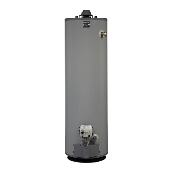
Owner's Manual
HydroSense
G as Water Heater
FOR POTABLE WATER HEATING ONLY.
NOT SUITABLE FOR SPACE HEATING.
NOT FOR USE IN MOBILE HOMES.
MODEL
NO.
153.331492
40 Gallon
153.331592
50 Gallon
• Safety
Instructions
• Installation
• Operation
• Care and Maintenance
• Troubleshooting
• Parts List
I =i _ , I=1 : {Ct'd,,,i
t'=_ ,"
For Your Safety
AN ODORANT
IS ADDED TO THE GAS USED BY THIS WATER HEATER.
This water
heater
complies
with ANSI Z21.10.1-
current
edition
regarding
the
accidental
or
unintended
ignition
of flammable
vapors,
such
as those emitted
by gasoline.
Read and understand
instruction
manual
and safety messages
before installing,
operating
or
servicing
this water
heater.
Failure
to follow instructions
and
safety messages
could result in
death
or serious
injury.
Instruction
manual
must remain
with water heater.
Si no puede leer o entender
el ingles
y necesita el manual de
instrucciones
en espa_ol, puede solicitarlo
al 1-800-821-2017.
NO
TRATE DE INSTALAR U OPERAR ESTE CALENTADOR
DE AGUA
SI NO ENTIENDE
LAS INSTRUCCIONES.
No hacer caso de esta
advertencia
podria originar lesiones graves o mortales.
WARNING:
If the
information
in these
instructions
is not followed
exactly, a fire
or explosion
may result causing
property
damage,
personal injury or death.
m Do not store or use gasoline
or other
flammable
vapors
and
liquids
in the
vicinity of this or any other appliance.
-- WHAT TO DO IFYOU SMELL GAS:
• Do not try to light any appliance.
• Do not touch
any electrical
switch;
do
not use any phone in your building.
• Immediately
call
your
gas
supplier
from a neighbor's
phone.
Follow
the
gas supplier's
instructions.
• If you cannot
reach your gas supplier,
call the fire department.
m lnstallation
and
service
must
be
performed
by
a
qualified
installer,
service agency orthe gas supplier.
PRINTED IN U.S.A. 1208
Sears,
Roebuck
and Co.,
Hoffman
Estates,
IL 60179
U.S.A
www.sears.com
PART NO. 186422-001
SUPERSEDES
186422-000
Advertisement
Table of Contents
Troubleshooting

Related Manuals for Kenmore HydroSense 153.331592


Summary of Contents for Kenmore HydroSense 153.331592
- Page 1 • Safety Instructions • Installation • Operation • Care and Maintenance • Troubleshooting • Parts List AN ODORANT IS ADDED TO THE GAS USED BY THIS WATER HEATER. WARNING: instructions accidental or explosion vapors, such damage, m Do not store or use gasoline flammable vicinity of this or any other appliance.
-
Page 2: Safe Installation, Use And Service
© Sears, Roebuck and Co. intheinstallation, use and servicing ofthis water heater. have been p rovided inthis manual and onyour o wn water heater towarn you and others of and instructions throughout I This is the safety alert symbol, it is used to alert you to potential... - Page 3 Read instruction manual before Improper • Do not operate water heater if flood damaged. • Inspect and replace anode. • Install in location with drainage. • Fill tank with water before operation. • Be alert for thermal expansion.
-
Page 4: Table Of Contents
TYPICAL INSTALLATION IMPORTANT INFORMATION ABOUT Installation Checklist ... INSTALLATION INSTRUCTIONS Removing the Old Water Heater ... Location Requirements ... Site Location ... Insulation Blankets ... Clearances and Accessibility ... Filling the Water Heater ... GAS SUPPLY ... Gas Requirements ... - Page 5 OPERATING YOURWATERHEATER ... Lighting Instructions ... Checking t he Draft ..BurnerFlames ... Emergency S hutDown ... Water T emperature Regulation ... SERVICE ANDADJUSTMENT ... Tank (Sediment) Cleaning ... VentSystem Inspection ..BurnerInspection ... Burner C leaning ..Housekeeping ...
-
Page 6: Product Warranty
For the second through twelfth year from purchase date, you must pay the labor cost for installation of the water heater. For three years from date of purchase, if this water heater is installed and operated in a single family home in accordance with the owner's manual instructions and all local applicable codes, if a part fails due to materials or workmanship, Sears will supply a free replacement part. -
Page 7: Customer Responsibilities
40 (151) Natural 153.331592 50 (189) Natural installed Carefully plan the place where you are going to put the water heater. Correct very important in preventing death from possible carbon monoxide ®.They will a rrange for poisoning and fires. contractors. -
Page 8: Materials And Basic Tools Needed
ROLL OF TEFLON USE FOR WATER AND GAS TAPE (USE ONLY ON WATER CONNECTIONS) 6 FOOT TAPE GARDEN HOSE WATER HEATER INSTALLATION KIT WITH FLEXIBLE CONNECTORS FOR 3/4" (19.05 ram) OR 1/2" (12.7 mm) THREADED COPPER PLUMBING AND FLEXIBLE WATER HEATER GAS CONNECTOR WITH FITTINGS. -
Page 9: Typical Installation
GET TO KNOW YOUR WATER HEATER Vent Pipe Draft Hood Anode (Not Shown) Hot Water Outlet Insulation Gas Supply Piping Manual Gas Shut-off Valve Ground Joint Union Drip Leg (Sediment Trap) * INSTALL INACCORDANCE WITH LOCAL CODES. * DRIP LEG AS REQUIRED BY LOCAL CODES. -
Page 10: Important Information About This Water Heater
This gas water heater was manufactured to voluntary safety standards to reduce the likelihood of a flammable vapor ignition incident. The new technology used in meeting these standards makes this product more sensitive to installation errors. Please review the following checklist and make any required installation upgrades or changes. -
Page 11: Removing The Old Water Heater
DRAIN VALVE 6" MAXIMUM T AIR GAP ® If you have copper piping to the water heater, the two copper water pipes can be cut with a hacksaw inches away from where See Figure... -
Page 12: Location Requirements
(Figure 8). HAZARD • If the water heater is located in an area that is subjected to lint and dirt, it may be necessary base-ring filter and flame-arrestor & Cleaning of the Base-Ring Combustion •... -
Page 13: Insulation Blankets
IMPORTANT: The water heater should be located in an area where leakage of the tank or connections will not result in damage to the area adjacent to the water heater or to lower floors of the structure. Due to the normal corrosive action of water, the tank wilt eventually leak after an extended period of time. -
Page 14: Filling The Water Heater
Filling the Water Heater Never use this water heater unless it is completely full of water. To prevent damage to the tank, the tank must be filled with water. Water must flow from the hot water faucet before turning "ON" gas to the water heater. -
Page 15: Gas Pressure
By formula: Cu. Ft. Per Hr. Required= The gas input of the water heater is marked on the water heater data plate. The heating value of the gas (BTU/FT 3) may be determined by consulting the local natural gas utility. -
Page 16: Combustion Air Supply & Ventilation
Combustion and ventilation air requirements are determined by the location of the water heater. The water heater may be located in either an open (unconfined) area or in a confined area or small enclosure such as a closet or small room. -
Page 17: All Air From Outdoors
Vertical Ducts Horizontal Single Opening Example: A water heater with an input rating of 50,000 BTUH using horizontal ducts would require each opening to have a minimum free area of 25 square inches. Minimum free area = 50,000 BTUH x 1 sq. in. ! 2000 BTUH = 25 sq. -
Page 18: Vent Pipe System
The vent pipe must be installed according to all local and state codes or, in the absence of local and state codes, the "National... -
Page 19: Vent Connectors
CAUTION: DO NOT common vent this water heater with any power vented appliance. Figures 19-21 are examples and may or may not be typical for your specific application. -
Page 20: Water System Piping
"Temperature (T & P) Relief Valve" on the water heater. A discharge line must be added to the opening of the T&P Relief Valve. Follow the instructions under "Temperature Relief Valve."... -
Page 21: Closed System/Thermal Expansion
IMPORTANT: Only a new temperature and pressure relief valve should be used with your water heater. Do not use an old or existing valve as it may be damaged working pressure of the new water heater. Do not place any... -
Page 22: Operating Yourwaterheater
Check the rating plate near the gas control valve/thermostat the correct gas. Do not use this water heater with any gas other than the one listed on the rating plate. If you have any questions or doubts, consult your gas supplier or gas utility company. -
Page 23: Checking The Draft
Emergency Shut Down IMPORTANT: Should overheating occur or the gas supply fails to shut off, turn off the water heater's manual gas control valve and call a qualified technician. Water Temperature Due to the nature of the typical gas water heater, the water... - Page 24 GASCONTROUTEMPERATUREKNOB NOTE: During tow demand periods when hot water is not being used, a lower thermostat setting losses and may satisfy your normal hot water needs. If hot water use is expected to be more than normal, thermostat setting may be required ©...
-
Page 25: Service Andadjustment
At least once a year, a visual inspection burner and pilot burner. See Figure 29. You should proper combustion. Soot build-up further use. Turn "OFF" gas to water heater and leave off until repairs are made, if vent pipe result in a fire causing sooted... -
Page 26: Housekeeping
Housekeeping Vacuum around base of water heater for dust, dirt, and lint on a regular basis. Fire and Explosion Do not obstruct combustion openings water heater. Do not use or store flammable vapor products such as gasoline, solvents or adhesives same room or area near water heater or other appliance. -
Page 27: Service
Turn the thermostat dial to the "OFF" position. located on the gas control valve/thermostat.) Turn off the gas to the water heater at the manual gas shut- off valve. Open nearby hot water faucets and leave them open to allow for draining. -
Page 28: Serviceinstructions Forthe Gas Control Valve/Thermostat
IMPORTANT: You can use the metal gas valve nipple that is already installed in the tank. install a new gas valve nipple, drain the water heater before removing the old one from the tank. 2. Screw the new gas control valve into the tank opening, then hand tighten it. - Page 29 ELECTRONIC CONTROL MODULE LOCKING THERMOPILE IGNITER TORX SCREW GAS VALVE ASSEMBLY (FRONT VIEW WITH ELECTRONIC CONTROL MODULE REMOVED) INLET SUPPLY LOCKING TORX PILOT BURNER SCREW TUBE LOCKING "TANK SENSOR LOCKING TUBE FIGURE 31. GAS VALVE ASSEMBLY GAS VALVE NIPPLE...
-
Page 30: Maintenance Of Yourwaterheater
At least annually, check the base-ring filter (Figure 37) for any dust or debris that may have accumulated screen. NOTE: If the water heater is located in an area that is subjected to tint and dirt, it may be necessary the base-ring filter more frequently. -
Page 31: Cleaning The Combustion Chamber Andflame-Arrestor
IM PORTANT: Keep the pilot orifice in the pilot when making the connection. Do not operate the water heater without the pilot orifice installed. Reattach the pilot shield and pilot assembly to the pilot bracket. -
Page 32: Piezoelectric Igniter S Ystem
* NOTE: SPARK GAP DISTANCE valve/ Testing Turn off the gas to the water heater at the manual gas shut-off valve. Watch the electrode tip while activating the igniter. A visible spark should jump from the electrode. To avoid shock, do not touch the burner or any metal part on the pilot or pilot assembly. -
Page 33: Troubleshooting Guide
If the flame is not with a 40 psi air... -
Page 34: Operational Conditions
Awater heater may appear to be leaking when in fact the water is condensation. This usually happens when: • A new water heater is filled with cold water for the first time. Burning produces... - Page 35 This is common at the time of start-up after installation and when incoming water is cold. Water in the water heater bottom or on the floor may be from condensation, DO NOT replace the water heater until a full inspection of all possible corrective steps taken.
-
Page 36: Troubleshooting Chart
PROBLEM LED STATUS 1 flash * 2 flashes * 3 flashes * 4 flashes * 5 flashes * GAS CONTROL VALVE/ THERMOSTAT 6 flashes * 7 flashes * 8 flashes * 6 second solid light followed by 4 flashes * 6 second solid light followed by 7 flashes * 6 second solid light... - Page 37 Repair faucets Advise customer Insulate piping Insulate piping Check with gas utility company Provide ventilation to water heater. Check flue way, flue baffle, and burner Clean flue, locate source and correct Check with gas utility company Replace thermostat Turn temperature...