Energate Z100 Operating And Installation Manual
Z100 pioneer 2 smart thermostat
Hide thumbs
Also See for Z100:
- Operating and installation manual (52 pages) ,
- Operating and installation manual (76 pages) ,
- Operating and installation manual (52 pages)
Table of Contents
Advertisement
Quick Links
Advertisement
Table of Contents

Subscribe to Our Youtube Channel
Related Manuals for Energate Z100


Summary of Contents for Energate Z100
- Page 1 Z100 Pioneer 2 Smart Thermostat Operating and Installation Manual AW000655-E...
- Page 2 Page 2...
- Page 3 Operating and Installation Manual Congratulations on the purchase of your new thermostat. It has been designed for easy programming to save on energy costs and allow a comfortable living environment. Features: Auto programming mode for your yearly heating and cooling needs ...
-
Page 4: Table Of Contents
Table of Contents OPERATING THE THERMOSTAT ..................... 7 Navigating the Controls ......................7 Home Screen ..........................8 Heat / Cool / Fan Icons ......................10 Setpoint Value Display ......................10 HELP button ..........................11 Title Bar ............................ 11 Default Schedule ........................12 Temporary Temperature Hold .................... - Page 5 Energy Events (also known as DRE / DRLC events) ..............28 Voluntary and Mandatory Energy Events................29 Starting a Temporary Temperature Hold during an Energy Event .......... 30 Energy Options Screen ......................31 Price Conservation Event ......................31 Conservation Screen ........................ 33 Indicators of Energy Events and Savings ..................
- Page 6 Replacing the Battery ....................... 46 Wiring Configuration ......................... 47 Setup Menu Options ......................... 48 Password ..........................48 Setpoint Range ........................49 Equipment Type ........................49 Equipment Settings ....................... 50 Conventional Systems ....................... 50 Heat Pump Systems......................51 Control Options ........................52 Device Info Screen........................
-
Page 7: Operating The Thermostat
OPERATING THE THERMOSTAT Navigating the Controls The function of the LEFT and RIGHT TAB buttons appears on the bottom of the display screen. Use the SCROLL (▲ ▼) buttons to adjust the temperature, move through the menus options, and change highlighted values. Press the MENU / SELECT (√) button to access the menu as well as to select or accept highlighted menu items. -
Page 8: Home Screen
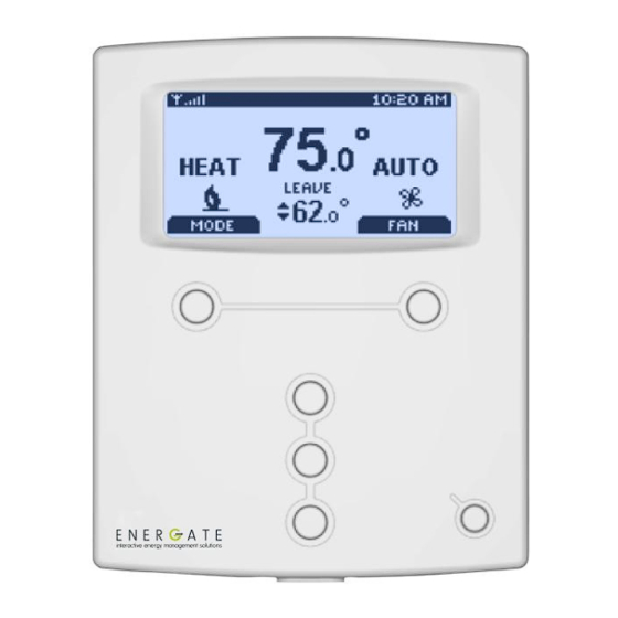
Home Screen The Home screen displays current temperature and operation data. When the Home screen is in Idle mode, the backlight is on with low brightness. Please note that icons such as heat or fan are animated when the equipment is running. Note: A SETPOINT (e.g., LEAVE) is identified by a name and specifies both heating and cooling target temperatures. - Page 9 By just pressing any of the buttons, the Home screen becomes Active, the backlight brightens and the MODE and FAN tabs are shown. Pressing the LEFT TAB button changes the thermostat mode (COOL/HEAT/AUTO/EMERG/OFF). The available options for the thermostat mode will depend on the type of heating or cooling equipment at your home.
-
Page 10: Heat / Cool / Fan Icons
Heat / Cool / Fan Icons Icon Description Heating mode (animated when furnace or heat pump is on). Cooling mode (animated when air conditioning or heat pump is on). Auxiliary heating on (animated). More than one heating stage on (animated). More than one cooling stage on (animated). -
Page 11: Help Button
HELP button The thermostat’s HELP button provides you with information on how to navigate through the individual menu screens. It will help you to quickly change settings without having to refer to this user manual; however, it does not replace this manual, so please keep this manual for future reference. -
Page 12: Default Schedule
Default Schedule The thermostat’s schedule is factory programmed with Energy Efficient START TIMES and SETPOINTS (listed below). Note: A SETPOINT has a pre-set name and specifies both heating and cooling target temperatures, as explained in detail in the Temperature Settings section. This default schedule may be modified as desired to meet your comfort and schedule requirements. - Page 13 Default Schedule (continued) SCHEDULE – Celsius Scale Monday to Friday Saturday & Sunday SETPOINT SETPOINT START START TIMES TIMES NAME HEAT COOL NAME HEAT COOL 6:00 am Wake 21.1°C 25.6°C 8:00 am Wake 21.1°C 25.6°C 8:00 am Leave 16.7°C 29.4°C 6:00 pm Return 21.1°C...
-
Page 14: Temporary Temperature Hold
Temporary Temperature Hold A Temporary Temperature Hold allows you to temporarily make the temperature warmer or cooler without affecting the pre-set programming. The thermostat will remain at the Temporary Hold temperature until the next scheduled SETPOINT. From the Home screen, press either of the SCROLL buttons to adjust either the HEAT (if the current operating mode is HEAT) or the COOL (if the current operating mode is COOL) of the active target SETPOINT, shown below the room temperature, with two... - Page 15 Temporary Temperature Hold (continued) Once the Temporary Hold is in effect, the SETPOINT name will be replaced by TEMPORARY. Note that a Temporary Hold can also be set by scrolling to the HOLD menu item at the Main Menu and selecting TEMPORARY as the Type of Hold, as it is explained further in the section describing the HOLD screen.
-
Page 16: Heating And Cooling Modes
Heating and Cooling Modes The thermostat is pre-set for heating operation (HEAT) but, as explained when describing the HOME SCREEN, you can manually (by pressing the LEFT TAB) change the thermostat mode between AUTO, HEAT, COOL, OFF, and EMERG. The available options for the thermostat mode will depend on the type of heating or cooling equipment at your home. -
Page 17: Main Menu
Main Menu From the Home Screen, pressing the MENU / SELECT button once (if the screen is active) or twice (if it is in the idle mode), the MAIN MENU appears as it is shown on the left. Using the SCROLL buttons, you can scroll to the desired menu item, as shown in the two screen shots on the left. -
Page 18: Temperature Settings
Temperature Settings A SETPOINT is identified by a NAME and specifies heating and cooling target temperatures. Example: If the SETPOINT is set to WAKE, with COOL temperature of 78°F and HEAT temperature of 70°F, a thermostat operating in AUTO mode will keep your dwelling’s temperature at the predefined HEAT or COOL temperature. -
Page 19: Advanced Schedule
Advanced Schedule The Advanced Schedule menu is reached by selecting the menu item ADV. SCHEDULE on the Main Menu By pressing the MENU / SELECT button, takes you to the ADVANCED SCHEDULE menu, where you can choose one of three menu items: SCHEDULE TYPE, SETPOINTS and SCHEDULE. -
Page 20: Schedule Type
Schedule Type The SCHEDULE TYPE screen allows you to choose among three different weekly schedule types. These are: Monday – Friday schedules are the same. 5/2 DAYS Saturday & Sunday schedules are the same 7 DAYS Every day of the week has an individual schedule. Monday –... -
Page 21: Setpoints
Setpoints The SETPOINTS screen shows on the left the list of names of the different SETPOINTS programmed in your thermostat and on the right the corresponding heating (in winter) and cooling (in summer) target temperatures. To change the HEAT and COOL temperature settings, SCROLL to the SETPOINT you want to change and press the MENU / SELECT button. -
Page 22: Schedule
Schedule The SCHEDULE determines when a SETPOINT such as WAKE begins. Only the start times are defined; the SETPOINT ends at the start of the next SETPOINT. From the ADVANCED SCHEDULE menu, choose the menu item SCHEDULE and press the MENU / SELECT button to view the SCHEDULE screen. -
Page 23: Hold Screen - Permanent, Timed, And Temporary Temperature Holds
Hold Screen - Permanent, Timed, and Temporary Temperature Holds The SCHEDULE can be overridden to maintain a desired SETPOINT through either a: Permanent Temperature Hold (hold until cancelled) Timed Temperature Hold Temporary Temperature Hold (hold until the next scheduled SETPOINT) Choose HOLD from the Main Menu. - Page 24 Hold Screen - Permanent, Timed, and Temporary Holds (continued) Timed Hold Once you choose the TIMED hold, you can change the date and time until it will be effective, by pressing the MENU/SELECT button. The date and/or time will be respectively underlined and you will be able to change them by using the SCROLL buttons.
- Page 25 Hold Screen - Permanent, Timed, and Temporary Holds (continued) Temporary Hold The Temporary Hold is set to override the thermostat schedule temporarily, but it will be cancelled by the next scheduled SETPOINT, as explained before in the section called Temporary Hold.
-
Page 26: Setting The Date & Time
Setting the Date & Time When the thermostat’s communication link to the utility’s network is active, the network periodically updates the date and time, so you will be prevented from modifying this setting. If the communications link is inactive (an “X” displayed in the top left corner), you can set the current date and time by selecting the TIME menu item from the USER OPTIONS menu. - Page 27 Setting the Date & Time (continued) The TIME screen will appear as shown at the left. To change between 12 and 24 hour clock formats, scroll to the CLOCK FORMAT menu item. Press MENU / SELECT. The setting will be underlined. You can change the format using the SCROLL buttons and then pressing SAVE CHANGES to accept the change.
-
Page 28: Energy Events And Price Events
Energy Events and Price Events Energy / Price Events occur during specific time intervals when your utility actively reduces consumer electricity consumption, or institutes higher energy prices to discourage consumption. This happens when your utility needs to reduce the load on the electricity grid, and these events are referred to as: ... -
Page 29: Voluntary And Mandatory Energy Events
An offset is the number of degrees above (in COOL mode) or below (in HEAT mode) the current target temperature setting programmed into the thermostat. If the utility selects a desired duty cycle, it will be shown as a percentage of time that your heating and/or air conditioning system operates, rather than the desired temperature. -
Page 30: Starting A Temporary Temperature Hold During An Energy Event
Starting a Temporary Temperature Hold during an Energy Event During an Energy Event you can always start a Temporary Hold through the Home Screen, following the procedure explained in the Temporary Hold section. In this case, when you press ACCEPT, a warning message will be displayed advising you that there is an Energy Event in progress, which are the limits specified by the event and when it will end. -
Page 31: Energy Options Screen
Energy Options Screen The Energy Options screen allows you to permanently disable Voluntary Energy Events. Choose ENERGY OPTIONS from the Main Menu to view this screen. The options are: OPT-IN and OPT-OUT. To change from OPT-IN to OPT-OUT, you need to SCROLL to OPT-OUT and press SAVE CHANGES. - Page 32 You can also permanently OPT-OUT of Price Conservation Events, by setting your thermostat’s Conservation to Maximum Comfort (described in more detail in next section). Note that it is possible to have an Energy Event (DRE/DRLC event) while there is a Price Event happening (e.g.
-
Page 33: Conservation Screen
Conservation Screen The Conservation feature allows you to choose your desired comfort level (i.e. from maximum comfort and no savings to maximum savings and minimum comfort) when energy prices increase. Please note that not all utilities provide price information over the communications link so this screen may not be activated for your program. - Page 34 By choosing the Balanced Level, price increases and temperature adjustments strike a balance between comfort and savings. The Savings Comfort Level places a higher value on savings over comfort such that the temperature adjustments are greater for a given price increase. Maximum Savings means that your thermostat will change the temperature in the direction of maximum energy savings every time there is an increase in the price of energy.
-
Page 35: Indicators Of Energy Events And Savings
Indicators of Energy Events and Savings The Thermostat has four Light Emitting Diodes (LEDs) located on the center portion of the case, below the LCD screen. These four LEDs are in order from left to right: BLUE, YELLOW, ORANGE and RED. BLUE This LED will light up when an energy (DRE/DRLC) event or a price conservation event is in progress. -
Page 36: Utility Text Messages
Utility Text Messages Your utility may send text messages to your thermostat to provide information. For example, they might inform you of upcoming events. A text message sent from your utility will be displayed when the thermostat is on the home screen. It will remain displayed until you acknowledge the message, until the message expires, or until your utility cancels the message. -
Page 37: User Options
User Options The USER OPTIONS menu allows you to set up the configurations of the price display, date and time, temperature and language. It also allows you to remind yourself when you have to change the filter of your equipment and also to save service information that you may need in future. Price Display Options From the Main Menu, SELECT the User Options menu item. -
Page 38: Filter Reminder
Filter Reminder You can program the Filter Reminder by going to the FILTER REMINDER screen from the USER OPTIONS menu. Once in the FILTER REMINDER screen, you can set (in months) when you need to change the filter. It can be set from 0 to 12 months. Setting it to 0 effectively disables the CHANGE FILTER reminder. -
Page 39: Temperature Units And Calibration
Temperature Units and Calibration The display can be set to display Fahrenheit (°F) or Celsius (°C) scales. Also if you measure the temperature yourself and believe the thermostat’s displayed temperature is off slightly you can easily calibrate the thermostat’s display by up to +/- 5.4°F (+/- 3°C) by following these steps. From the USER OPTIONS menu select TEMPERATURE. -
Page 40: Service Information
Service Information Information regarding your service contractor can be programmed into the thermostat for future reference from the SERVICE screen, which can be accessed through the USER OPTIONS menu. Choose SERVICE from the USER OPTIONS menu. Press EDIT NAME and enter the name and contact information using the MENU / SELECT button to navigate to each letter position and the SCROLL buttons to change each letter. -
Page 41: Installation And Maintenance
INSTALLATION AND MAINTENANCE Mounting the Thermostat Install the thermostat approximately 5 feet (1.5m) above the floor in an area with good air circulation at average temperature. Avoid locations with drafts or dead spots behind doors, hot or cold air ducts, sunlight or radiant heat from appliances, concealed pipes or chimneys and unconditioned areas such as outside walls behind the thermostat. -
Page 42: Mounting The Thermostat (Continued)
Mounting the Thermostat (continued) Remove back-plate from thermostat housing. Place thermostat housing as shown Grab battery-tab and pull away from the above. battery. It is very important to engage the top Do not touch the ESD-sensitive components hinge first. unless properly grounded Page 42... -
Page 43: Mounting The Thermostat (Continued)
Mounting the Thermostat (continued) CAUTION: Do not press on the front housing as shown Press down at the bottom of the thermostat above. housing until the housing snaps into position. This may cause the LCD to crack and/or break! Page 43... -
Page 44: Mounting The Outdoor Sensor
Mounting the Outdoor Sensor The outdoor sensor should be mounted in a shaded location, out of direct sunlight. The thermostat will automatically detect the outdoor sensor and display its readings. Cleaning the Thermostat The thermostat can be cleaned with a soft cloth lightly dampened with isopropyl alcohol (IPA). Excessive IPA or use of other solvents may damage the LCD! Page 44... -
Page 45: Removing Thermostat Front Housing From Backplate
Removing Thermostat Front Housing from Backplate To remove the thermostat front housing from the backplate, press the plastic tab located at the bottom of the thermostat. Pull the bottom of the front housing forward and remove. WARNING: do not use metallic tools when removing battery or backplate; this may damage the thermostat. -
Page 46: Replacing The Battery
Replacing the Battery A LOW BATTERY WARNING will appear when the battery falls below 10% of its rated capacity. This procedure does not lose the thermostat settings; however, time settings will require re- programming if communications are not restored. Replace with a CR-2032 battery. Many government agencies promote and have battery recycling programs. -
Page 47: Wiring Configuration
Wiring Configuration The thermostat should be wired by a licensed technician familiar with HVAC installation. Conventional Systems (CONV) Common(GND) Power (24VAC) 3 RS OUT Outdoor Sensor 1st Stage Heat W1 10 4 RS GND Sensor Ground 5 FILTER Filter 1st Stage Cool Y1 12 2nd Stage Cool Y2 13 2nd Stage Heat W2 14 Heat Pump Systems (HP) -
Page 48: Setup Menu Options
Setup Menu Options WARNING: Changing settings in the SETUP can damage the HVAC system and should only be done by a qualified HVAC technician. Password Two levels of password protection are programmed in the thermostat: USER and INSTALLER. Both password levels will timeout after 20 minutes of the last button press and force you to re-enter a password. -
Page 49: Setpoint Range
Setpoint Range The SETPOINT RANGE sub menu defines the Maximum and Minimum temperatures allowed in the HEAT and COOL modes. Adjusting these temperatures limits the temperature ranges allowed when setting SETPOINT temperatures. Equipment Type WARNING: The thermostat must be configured correctly to match the equipment type. The number of cooling and heating stages must be defined in the Conventional or Heat Pump setting. -
Page 50: Equipment Settings
Equipment Settings Conventional Systems You must enter an Installer Password to access the EQUIPMENT SETTINGS from the Main Menu. The following settings can be changed for Conventional Systems: DEFAULT OPTION MIN ON/OFF TIME 3 MIN 1-10 MIN Minimum cycle time for the furnace/air conditioner. FAN ON IN HEAT The fan turns on when the The furnace waits until enough... -
Page 51: Heat Pump Systems
Heat Pump Systems You must enter an Installer Password to access the EQUIPMENT SETTINGS from the Main Menu. The following settings can be changed for Heat Pump Systems: DEFAULT OPTION MIN ON/OFF TIME 3 MIN 1-10 MIN Minimum cycle time for the heat pump/auxiliary heater. ALLOW HP+AUX ON Allows the Heat Pump and Does not allow Heat Pump and... -
Page 52: Control Options
Control Options You must enter an Installer Password to access the CONTROL menu from the Main Menu. The following settings can be changed: DEFAULT OPTION CHANGE 0-6°F 2°F (1°C) HYSTERESIS (0-3°C) Defines the number of degrees the temperature must go beyond a setpoint prior to changing from HEAT to COOL mode or vice versa in AUTO mode. -
Page 53: Device Info Screen
CONFIG ID: Customer Configuration File Identification Number and Version. Both are numbers from 0 to 255, separated by a dot. When no Customer Configuration File has been programmed, the Value shown will be NOT AVAILABLE. In this case, the standard Energate default values will be used. Page 53... - Page 54 Version. Both are numbers from 0 to 255, separated by a dot. When no Customer Configuration File has been programmed, the Value shown will be NOT AVAILABLE. In this case, the standard Energate default values will be used. Page 54...
-
Page 55: Zigbee Link Info Screen
ZigBee Link Info Screen The Link Info screen is also read-only and it is available through the Setup menu. The Installer password must be entered to access the screen. The ZIGBEE LINK INFO screen provides the following information: The ZigBee Link Icon, as described in the Title Bar section of this manual. ... - Page 56 ZigBee Link Info Screen (continued) STATUS: The text label inside the box describes the status of the communication link Possible states of the communication link: SEARCHING FOR RADIO SEARCHING FOR NETWORK JOINING NETWORK SEARCHING FOR TRUST CENTER WAITING FOR SECURE LINK SEARCHING FOR ESP WAITING FOR VALID CONNECTION CONNECTION ACTIVE...
-
Page 57: Reset Screen
Reset Screen The Thermostat has three different resets to Factory Default values: • THERMOSTAT RESET • USER CONFIGURATION RESET • SECURITY KEYS RESET The following sections provide additional information on each of these resets. Page 57... -
Page 58: Thermostat Reset
Thermostat Reset A THERMOSTAT RESET restores the thermostat to the following original manufacturer settings HEAT COOL WAKE 70.0ºF 78.0ºF LEAVE 62.0ºF 85.0ºF RETURN 70.0ºF 78.0ºF SETPOINTS SLEEP 62.0ºF 82.0ºF UNOCCUPIED 62.0ºF 85.0ºF OCCUPIED 70.0ºF 78.0ºF SETPOINT 7 62.0ºF 85.0ºF HOLD 70.0ºF 78.0ºF SCHEDULE... - Page 59 Thermostat Reset (continued) UNITS FAHRENHEIT (ºF) TEMPERATURE USER [1234] OFF PASSWORD INSTALLER [INST] HEAT 91.0ºF (32.8ºC) 54.0ºF (12.2ºC) SETPOINT RANGE COOL 93.0ºF (33.9ºC) 56.0ºF (13.3ºC) # OF COOL STAGES EQUIPMENT TYPE CONVENTIONAL # OF HEAT STAGES MIN ON/OFF TIME 3 MIN EQUIPMENT SETTINGS FAN ON IN HEAT CHANGE HYSTERESIS...
-
Page 60: User Configuration Reset
User Configuration Reset The USER CONFIGURATION RESET will only restore the following settings to the factory default values listed in the previous Thermostat Reset section: SETPOINTS CLOCK FORMAT SCHEDULE LANGUAGE COMFORT SETTING TEMPERATURE UNITS Security Keys Reset The thermostat ships from the factory with an initial security key that allows the thermostat to set an initial temporary connection with the utility. -
Page 61: Conventional System Test
Conventional System Test This procedure allows the installer to bypass delays associated with the minimum on/off times. OUTPUT TESTED PROCEDURE EXPECTED RESULT Mode = OFF Fan should turn on. Fan = change from AUTO to ON Mode = COOL Lower the setpoint by at least -3°F (-2°C) First stage cooling should stage cooling from room temperature and press... -
Page 62: Heat-Pump System Test
Heat-Pump System Test This procedure allows the installer to bypass delays associated with the minimum on/off times. OUTPUT TESTED PROCEDURE EXPECTED RESULT Mode = OFF Fan should turn on. Fan = change from AUTO to ON Mode = COOL stage cooling Set the setpoint by at least -3°F (-2°C) First stage cooling should below room temperature and press... -
Page 63: Product Conformity
2. This device must accept any interference, including interference that may cause undesired operation. Contains Radio Module FCC ID: WUR-RM30; Industry Canada: 8022A-RM30 Caution You are cautioned that any changes or modifications not expressly approved by Energate, Inc. could void your authority to operate this equipment. Page 63... -
Page 64: Note
Note: This equipment has been tested and found to comply with the limits for a Class B digital device, pursuant to part 15 of the FCC Rules. These limits are designed to provide reasonable protection against harmful interference in a residential installation. This equipment generates, uses and can radiate radio frequency energy and, if not installed and used in accordance with the instructions, may cause harmful interference to radio communications. - Page 65 Page 65...
- Page 66 Page 66...
- Page 67 Page 67...
- Page 68 Page 68 © All Rights Reserved US Patent No. 7,737,762...
Need help?
Do you have a question about the Z100 and is the answer not in the manual?
Questions and answers