Table of Contents
Advertisement
Quick Links
I
NSTALLATION
These furnaces comply with requirements em-
bodied in the American National Standard / Na-
tional Standard of Canada ANSI Z21.47·CSA-
2.3 Gas Fired Central Furnaces.
ATTENTION INSTALLING PERSONNEL
As a professional installer, you have an obligation to know the product better than the customer.
Prior to actual installation, thoroughly familiarize yourself with this Instruction Manual.
Pay special attention to all safety warnings. Often during installation or repair, it is possible to place yourself
in a position which is more hazardous than when the unit is in operation.
Remember, it is your responsibility to install the product safely and to know it well enough
Safety is a matter of common sense...a matter of thinking before acting.
Most dealers have a list of specific, good safety practices...follow them.
The precautions listed in this Installation Manual are intended as supplemental to existing practices.
However, if there is a direct conflict between existing practices and the content of this manual,
IO-446A
3/2014
is a registered trademark of Maytag Corporation or its related companies and is used under license. All rights reserved.
I
NSTRUCTIONS FOR
ADS(H,S)8 / AMEH8 G
(CATEGORY I )
Installer: Affix all manuals adjacent to the unit.
RECOGNIZE THIS SYMBOL AS A SAFETY PRECAUTION.
This includes all safety precautions and related items.
to be able to instruct a customer in its safe use.
the precautions listed here take precedence.
NOTE: Please contact your distributor or our website listed below
for the applicable Specification Sheet referred to in this manual.
G
OODMAN WILL NOT BE RESPONSIBLE FOR ANY INJURY OR PROPERTY
DAMAGE ARISING FROM IMPROPER SERVICE OR SERVICE PROCEDURES
I
F YOU INSTALL OR PERFORM SERVICE ON THIS UNIT
RESPONSIBILITY FOR ANY PERSONAL INJURY OR PROPERTY DAMAGE
. M
WHICH MAY RESULT
INSTALL OR SERVICE HEATING AND AIR CONDITIONING EQUIPMENT
5151 San Felipe Suite 500 • Houston, TX 77056
www.goodmanmfg.com • www.amana-hac.com
© 2011 - 2014 Goodman Manufacturing Company, L.P.
*M(H,S)8 / GD(H,S)8 / GHS8 / GME8
F
AS
URNACE
WARNING
,
YOU ASSUME
ANY JURISDICTIONS REQUIRE A LICENSE TO
.
.
Advertisement
Table of Contents
Troubleshooting

Related Manuals for Amana GDH8


Summary of Contents for Amana GDH8
- Page 1 INSTALL OR SERVICE HEATING AND AIR CONDITIONING EQUIPMENT 5151 San Felipe Suite 500 • Houston, TX 77056 IO-446A www.goodmanmfg.com • www.amana-hac.com 3/2014 © 2011 - 2014 Goodman Manufacturing Company, L.P. is a registered trademark of Maytag Corporation or its related companies and is used under license. All rights reserved.
-
Page 2: Table Of Contents
Table of Contents ..........................5 AFETY ONSIDERATIONS ...................... 6 DDITIONAL AFETY ONSIDERATIONS ........................... 6 HIPPING NSPECTION (ESD) P ..................6 LECTROSTATIC ISCHARGE RECAUTIONS ..........................7 NSTALLER ..........................7 RODUCT PPLICATION REMOVED WARRANTY SECTION ....................7 ....................8 OCATION EQUIREMENTS AND ONSIDERATIONS ...................... - Page 3 EASUREMENT ATURAL ........................... 30 EMPERATURE ..................... 30 IRCULATOR LOWER PEED DJUSTMENT ..................30 IRCULATOR LOWER IMING DJUSTMENT (GDH8, GME8, *MH8, AMEH8 ADSH8 ) ..... 31 ETTING URNACE PERATING MODELS ONLY ..........................31 PERATIONAL HECKS ..........................31 URNER LAME ......................... 31...
- Page 4 HART ......................39 LOWER ERFORMANCE *M(H/S)8 ..........................39 GDS8 / ADSS8 & GHS8 ......................40 ......................41 LOWER ERFORMANCE GDH8 / ADSH8 ........................41 ......................42 LOWER ERFORMANCE GME8 ............................. 42 ......................43 LOWER ERFORMANCE AMEH8 ........................... 43 *(M, D, H)S8 / ADSS8 W ..................
-
Page 5: Safety Considerations
WARNING WARNING O PREVENT PERSONAL INJURY OR DEATH DUE TO IMPROPER WILL NOT BE RESPONSIBLE FOR ANY INJURY OR PROPERTY OODMAN INSTALLATION ADJUSTMENT ALTERATION SERVICE OR MAINTENANCE DAMAGE ARISING FROM IMPROPER SERVICE OR SERVICE PROCEDURES REFER TO THIS MANUAL OR ADDITIONAL ASSISTANCE OR F YOU INSTALL OR PERFORM SERVICE ON THIS UNIT YOU ASSUME INFORMATION... -
Page 6: Dditional Afety
DDITIONAL AFETY ONSIDERATIONS • This furnace is approved for Category I Venting only. • Provisions must be made for venting combustion products outdoors through a proper venting system. The length of flue pipe could be a limiting factor in locating the furnace. HIPPING NSPECTION All units are securely packed in shipping containers tested... -
Page 7: Product Application
2. Firmly touch a clean, unpainted, metal surface of the • The vent system is permanently installed per these furnaces near the control. Any tools held in a person’s installation instructions. hand during grounding will be discharged. • A room thermostat is used to control the furnace. Fixed 3. -
Page 8: Location Requirements Andc
A copy of the National Fuel Gas Code (NFPA 54/ANSI Z223.1) WARNING can be obtained from any of the following: American National Standards Institute O PREVENT POSSIBLE EQUIPMENT DAMAGE PROPERTY DAMAGE 1430 Broadway PERSONAL INJURY OR DEATH THE FOLLOWING BULLET POINTS MUST BE New York, NY 10018 OBSERVED WHEN INSTALLING THIS UNIT National Fire Protection Association... -
Page 9: Clearances And Accessibility
• If the furnace is used in connection with a cooling unit, Vent Pipe Clearance to Combustibles- 6" using Single Wall Connector or 1" install the furnace upstream or in parallel with the using B-1 vent. cooling unit coil. Premature heat exchanger failure will result if the cooling unit coil is placed ahead of the Top - 1"... -
Page 10: Horizontal Installation
ORIZONTAL NSTALLATION XISTING URNACE EMOVAL NOTE: When an existing furnace is removed from a venting system serving other appliances, the venting system may be too large to properly vent the remaining attached appliances. The following vent testing procedure is reproduced from the American National Standard/National Standard of Canada for Gas-Fired Central Furnaces ANSI Z21.47-Latest Edi- tion, CSA-2.3-Latest Edition Section 1.23.1. -
Page 11: Categoryi Venting
290°F reduced heat loss by reducing air infiltration and escape around ® ® Note: This kit is for use on Amana brand and Goodman brand 80% AFUE, doors and windows. These changes have helped in reducing 33” tall “H” and “S” model furnaces installed in the upfl ow position only. -
Page 12: Exterior Masonry Chimneys
The minimum vent diameter for the Category I venting system 8. Install the chimney top with the four screws retained is as shown: from step 6 onto the new chimney transition bottom from the transition bottom kit. 9. Remove the induced draft blower and install the new MINIMUM VENT MODEL chimney assembly to it using the three screws retained... -
Page 13: Checklist Summary
WARNING Proper Chimney Termination? (Check 1) OSSIBILITY OF PROPERTY DAMAGE PERSONAL INJURY OR DEATH DAMAGING CONDENSATION CAN OCCUR INSIDE MASONRY CHIMNEYS (80% AFUE WHEN A SINGLE FAN ASSISTED ATEGORY APPLIANCE FURNACE IS VENTED WITHOUT ADEQUATE DILUTION AIR O NOT CONNECT AN FURNACE TO A MASONRY CHIMNEY UNLESS THE FURNACE IS COMMON VENTED WITH A DRAFT HOOD EQUIPPED Chimney channel... -
Page 14: Check 3 - Chimney Crown
3 - C 10' or Less HECK HIMNEY ROWN ONDITION Damage from condensate usually shows up first in the crown. 2' Min. 2' Min. If any of the following trouble signs are present, the condition of 3' Min. the crown is not satisfactory: a) Crown leaning b) Bricks missing Wall or... -
Page 15: Check 6 - Dilution Air
Flexible liners should be hung straight or nearly straight. If it is • Extremely cold weather spiraled in the chimney and in good condition, it should be • Long vent connectors rehung. To do this, break the top seal; pull up and cut off the •... -
Page 16: Relining
Some manufacturers of flexible liners offer an insulation sleeve 4 - R ELINING designed to be added to the liner before it is installed in the Relining options include B vent and flexible liners. chimney. (Poured insulation, either vermiculite or other materi- als, is no longer recommended.) Insulation will need to be added If the chimney has diagonal offsets, B vent probably cannot be to the flexible liner if:... -
Page 17: Wiring Harness
Line voltage connections can be made through either the right IRING ARNESS or left side panel. The furnace is shipped configured for a right The wiring harness is an integral part of this furnace. Field side electrical connection. To make electrical connections alteration to comply with electrical codes should not be re- through the opposite side of the furnace, the junction box must quired. -
Page 18: Volt Thermostatw
To ensure proper unit grounding, the ground wire should run 3. Connect the common terminal of the field supplied from the furnace ground screw located inside the furnace junc- relay to the “LINE-H” terminal on the furnace ignition tion box all the way back to the electrical panel. NOTE: Do control. -
Page 19: 115 Volt Line Connection Of
LEANER is powered anytime the pressure switch is closed and provides (GME8, AMEH8, GDH8, ADSH8 & (A/G)MH8 MODELS ONLY) 24 VAC humidifier control. Remove the yellow wire and con- nect a field supplied jumper wire with a “piggyback” terminal to WARNING the pressure switch terminal. -
Page 20: High Altitude Derate
Models using 2-Stage Gas Valves LTITUDE ERATE M anifold Pre s s ure IMPORTANT NOTE: The furnace, as shipped, requires no Pre s s ure change to run between 0 - 5500 feet. Do not attempt to increase Altitude Orifice Sw itch High Change... -
Page 21: Upflow Installations
• Use pipe joint compound on male threads only. Pipe PFLOW NSTALLATIONS joint compound must be resistant to the action of the A ground joint union, drip leg, and manual shutoff valve must fuel used. also be supplied by the installer. In some cases, the installer •... -
Page 22: P G T P
ROPANE ANKS AND IPING ROPANE IPING HARTS Sizing Between First and Second Stage Regulator* WARNING Maximum Propane Capacities listed are based on 2 psig pressure drop at 10 psig setting. Capacities in 1,000 BTU/hour. Pipe or F THE GAS FURNACE IS INSTALLED IN A BASEMENT AN EXCAVATED Nominal Pipe Size Tubing Size, O.D. -
Page 23: Checking Duct Static
When the furnace is used in connection with a cooling unit, the 2. Measure the static pressure of the supply duct. (Positive furnace should be installed in parallel with or on the upstream Pressure) side of the cooling unit to avoid condensation in the heating 3. -
Page 24: Circulation Air Filters
Igniter warm up begins after 15 second prepurge expires. NOTE: Dip switch positions referenced in this section applies • Low and high-stage gas valves open at end of igniter to (GME8, AMEH8, GDH8, ADSH8 & (A/G)MH8 MODELS warm up period, delivering gas to burners and establishing ONLY). flame. -
Page 25: Cooling Mode
• Circulator blower is de-energized following a heat off delay TART ROCEDURE DJUSTMENT period (selectable 100 or 150 seconds; factory set at 150 seconds). Furnace must have a 115 VAC power supply properly connected If the furnace is operating in the low-stage heating mode and grounded. -
Page 26: Furnace Shutdown
8. Replace the door on the front of the furnace. 9. Open the manual gas valve external to the furnace. 10. Turn on the electrical power supply to the furnace. 11. Set the room thermostat to the desired temperature. NOTE: There is an approximate 30 second delay between ther- mostat energizing and burner firing. - Page 27 Open to INLET GAS SUPPLY PRESSURE Atmosphere Natural Gas Minimum: 4.5" w.c. Maximum: 10.0" w.c. High Fire Regulator Propane Gas Minimum: 11.0" w.c. Maximum: 13.0" w.c. Outlet Adjust Regulator Pressure Boss 9. Turn OFF all electrical power and gas supply to the Vent system.
-
Page 28: Gas Manifold Pressurem
1. Turn OFF gas to furnace at the manual gas shutoff valve ANIFOLD RESSURE EASUREMENT AND DJUSTMENT external to the furnace. CAUTION 2. Connect a calibrated water manometer (or appropriate gas pressure gauge) at either the gas valve inlet pressure O PREVENT UNRELIABLE OPERATION OR EQUIPMENT DAMAGE Tap or the gas piping drip leg. -
Page 29: Gas Input Rate Measurement
9. Remove regulator cover screw from the outlet pressure 10. Remove regulator cover screw from the high (HI) outlet regulator and turn screw clockwise to increase pressure pressure regulator adjust tower and turn screw clockwise or counterclockwise to decrease pressure. Replace to increase pressure or counterclockwise to decrease regulator cover screw. -
Page 30: Temperature Rise
Installation’s seconds per cubic foot: 34 sec/ ft 4. Adjust temperature rise by adjusting the circulator blower speed. Increase blower speed to reduce temperature rise. Conversion Factor (hours to seconds): 3600 sec/hr Decrease blower speed to increase temperature rise. Input = (Htg. value x 3600) ÷ seconds per cubic foot Refer to the following section for speed changing details. -
Page 31: Etting Urnace Perating
Flames should be stable, quiet, soft, Adjustment Switch and blue (dust may cause orange tips but they must not be yellow). Flames should extend directly outward from the burn- (GDH8, GME8, ETTING URNACE PERATING ers without curling, floating, or lifting off. Flames must not... -
Page 32: Safety Circuit Description
AFETY IRCUIT ESCRIPTION ROUBLESHOOTING ENERAL (ESD) P LECTROSTATIC ISCHARGE RECAUTIONS A number of safety circuits are employed to ensure safe and NOTE: Discharge body’s static electricity before touching unit. proper furnace operation. These circuits serve to control any An electrostatic discharge can adversely affect electrical potential safety hazards and serve as inputs in the monitoring components. -
Page 33: Maintenance
ESETTING OCKOUT ILTERS Furnace lockout results when a furnace is unable to achieve WARNING ignition after three attempts. It is characterized by a non-func- O AVOID PROPERTY DAMAGE PERSONAL INJURY OR DEATH tioning furnace and a one flash diagnostic LED code from the DISCONNECT ELECTRICAL POWER BEFORE REMOVING FILTERS EVER red LED. -
Page 34: Flame Sensor (Qualified Servicer Only )
LAME ENSOR UALIFIED ERVICER CAUTION Under some conditions, the fuel or air supply can create a HE IGNITER IS FRAGILE AND CAN BE EASILY DAMAGED SE EXTREME nearly invisible coating on the flame sensor. This coating acts CAUTION WHEN REMOVING THE BURNER BOX TOP as an insulator causing a drop in the flame sense signal. -
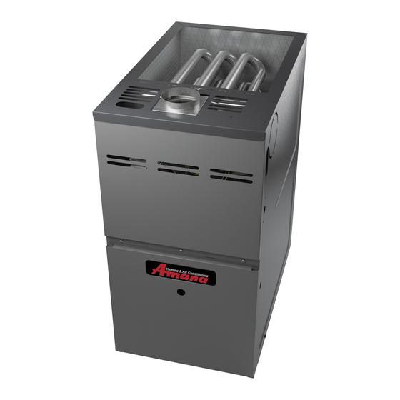
Page 35: Component Id
OMPONENT Tubular Heat Exchanger Pressure Switch Flue Pipe Connection Induced Draft Blower (Chimney Transition Top Shipped Loose) Gas Line Entrance Gas Valve Rollout Limit Junction Box Wiring Harness Grommet Gas Manifold Gas Line Entrance (Alternate) Inshot Burner Transformer Circulator Blower Blower Door Interlock Switch Integrated Control Module... -
Page 36: Troubleshooting Chart
ROUBLESHOOTING HART Associated Fault Symptoms of Cautions Possible Corrective Description(s) Abnormal Operation LED Code Action & Notes Causes • Turn power OFF • Assure 115 and 24 volt • Furnace fails to operate. NONE • No 115 volt power to •... -
Page 37: Troubleshooting Chart
ROUBLESHOOTING HART Associated Fault Symptoms of Cautions Associated Possible Causes Corrective Action LED Code Description(s) Abnormal Operation & Notes LED Code • Check primary limit. • Turn power OFF • Insufficient conditioned air • Circulator blower runs • Primary limit Replace if necessary. -
Page 38: Troubleshooting
ROUBLESHOOTING HART Fault Symptoms of Associated Cautions Associated Possible Causes Corrective Action Description(s) Abnormal Operation & Notes LED Code LED Code • Improperly connected • Furnace not operating. • Problem with • Check and correct wiring • Turn power OFF igniter. -
Page 39: Blower Performance Data
LOWER ERFORMANCE *M(H/S)8 (CFM & Temperature Rise vs. External Static Pressure) EXTERNAL STATIC PR ESSUR E (Inch es Water Colu mn) Tons AC Model Motor 0. 1 at 0.5" Heating Speed Speed As Shipped CFM RISE CFM RISE CFM R ISE CFM RISE CFM RISE CFM C FM CFM H IGH 1521 ----... -
Page 40: Gds8 / Adss8 & Ghs8
LOWER ERFORMANCE GDS8/ADSS8 (CFM & Tem perature Rise vs. Exte rna l Static Pre ssure) Model Tons AC EXTERNAL STATIC PRESSURE (Inches W ater Column) Motor at 0.5" Speed Heating Speed CFM RISE CFM RISE CFM RISE CFM RISE CFM RISE CFM CFM CFM As Shipped HIGH 1353... -
Page 41: Gdh8 / Adsh8
LOWER ERFORMANCE GDH8 / ADSH8 (CFM & Temperature Rise vs. External Static Pressure) Model Tons AC EXTERNAL STATIC PRESSURE (Inches W ater Column) Motor at 0.5" Heating Speed Speed As Shipped CFM RISE CFM RISE CFM RISE CFM RISE CFM RISE CFM CFM CFM... -
Page 42: Gme8
LOWER ERFORMANCE GME8 (CFM & Temperature Rise vs. External Static Pressure) Model Tons AC EXTERNAL STATIC PRESSURE (Inches Water Column) Motor Speed at 0.5" Heating Speed As Shipped CFM RISE CFM RISE CFM RISE CFM RISE CFM RISE CFM CFM CFM T1 - YELLOW ---- ----... -
Page 43: Blower Performance Data Ameh8
LOWER ERFORMANCE AMEH8 Model Tons AC EXTERNAL STATIC PRESSURE (Inches W ater Column) Motor Speed at 0.5" Heating Speed CFM RISE CFM RISE CFM RISE CFM RISE CFM RISE CFM CFM CFM As Shipped T1 - YELLOW ---- ---- ---- ---- ---- T2 - RED... -
Page 44: (M, D, H)S8 / Adss8 W
*(M, D, H)S8 / ADSS8 W IRING DIAGRAM WARNING:DISCONNECT POWER BEFORE HUMIDIFIER INTEGRATED CONTROL MODULE SERVICING.WIRING TO UNIT MUST BE PROPERLY POLARIZED AND GROUNDED. XFMR (6) 24 VAC GND (8) HUMIDIFIER MVC (9) VALVE MV (12) DIAGNOSTIC ID BLOWER PRESSURE FUSE AUXILIARY SWITCH... -
Page 45: Gas Valve
GME8 / AMEH8 W IRING DIAGRAM HITE ODGERS ALVE INTEGRATED WARNING:DISCONNECT POWER BEFORE HUMIDIFIER CONTROL MODULE SERVICING.W IRING TO UNIT MUST BE PROPERLY POLARIZED AND GROUNDED. XFMR (6) GND (8) 24 VA C MVC (9) HUMIDIFIER VALVE MVH (12) MVL (2) ID BLOWER PRESSURE SWITCH... -
Page 46: Honeywell Gas Valve
GME8 / AMEH8 W IRING IAGRAM ONEYWELL ALVE WARNING: DISCONNECT POWER BEFORE HUMIDIFIER INTEGRATED CONTROL MODULE SERVICING. WIRING TO UNIT MUST BE PROPERLY POLARIZED AND GROUNDED. XFMR (6) GND (8) 24 VAC HUMIDIFIER MVC (9) VALVE MVH (12) MVL (2) ID BLOWER PRESSURE AUXILIARY... -
Page 47: Gas Valve
*(M,D)H8 / ADSH8 W IRING IAGRAM HITE ODGERS ALVE WARNING:DISCONNECT POW ER BEFORE HUMIDIFIER INTEGRATED CONTROL MODULE SERVICING.WIRING TO UNIT MUS T BE PROPERLY POLARIZED AND GROUNDED. XFMR (6) GND (8) 24 VAC HU MIDIF IER MVC (9) VALVE MVH (12) MVL (2) ID BLOWER PRESSURE... -
Page 48: Honeywell Gas Valve
*(M,D)H8 / ADSH8 W IRING IAGRAM ONEYWELL ALVE INTEGRATED WARNING:DISCONNECT POWER BEFORE HUMIDIFIER CONTROL MODULE SERVICING.WIRING TO UNIT MUST BE PROPERLY POLARIZED AND GROUNDED. XFMR (6) GND (8) 24 VAC HUMIDIFIER MVC (9) VALVE MVH (12) MVL (2) ID BLOWER PRESSURE AUXILIARY SWITCH...
Need help?
Do you have a question about the GDH8 and is the answer not in the manual?
Questions and answers