Table of Contents
Advertisement
Quick Links
Advertisement
Table of Contents

Related Manuals for Dell S4810–ON


Summary of Contents for Dell S4810–ON
- Page 1 Installing the S4810 System April 2014...
- Page 2 WARNING: A WARNING indicates a potential for property damage, personal injury, or death. Copyright © 2014 Dell Inc. All rights reserved. This product is protected by U.S. and international copyright and intellectual property laws. Dell ™...
-
Page 3: Table Of Contents
Contents 1 About this Guide......................5 ..........................5 Information Symbols ..........................6 Related Documents 2 The S4810–ON System....................7 ............................7 Introduction ....................8 Orderable S4810–ON Components ............................8 Prerequisite ..............................9 Features ............................... 9 Ports ............................9 System Status .............................9 LED Displays 3 Site Preparations......................11 ............................11 Site Selection ..........................11... - Page 4 ............................23 AC Power ............................24 DC Power ........................24 Hot-Swap Units in a Stack 5 Power Supplies......................25 ............................25 Components ....................26 Installing an AC or DC Power Supply ....................26 Replacing an AC or DC Power Supply 6 Fans..........................27 ............................27 Components ........................
-
Page 5: About This Guide
About this Guide This guide provides site preparation recommendations, step-by-step procedures for rack mounting and desk mounting, inserting optional modules, and connecting to a power source. CAUTION: To avoid electrostatic discharge (ESD) damage, wear grounding wrist straps when handling this equipment. WARNING: Only trained and qualified personnel can install this equipment. -
Page 6: Related Documents
Related Documents For more information about the S4810–ON system, refer to the Dell Networking S4810–Open Networking (ON) Getting Started Guide. NOTE: For the most recent documentation, visit iSupport: http://www.dell.com/support/my- support. About this Guide... -
Page 7: The S4810-On System
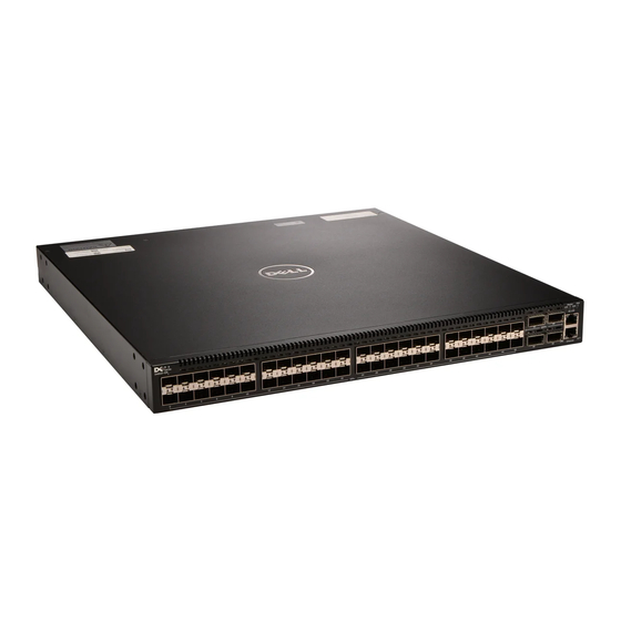
The following sections describe the Dell Networking S4810–ON system. Introduction The Dell Networking S4810–ON platform is a next-generation switch/router designed to meet the requirements for distributed data center cores. It is a one-rack unit (RU) chassis that supports 48 ports of 10GbE small form-factor pluggable plus (SFP+) and four quad small form-factor pluggable plus (QSFP+) ports. -
Page 8: Orderable S4810-On Components
S4810–ON Series — AC Power supply with airflow from the PSU side to the I/O side For a list of supported optics, refer to the S4810–ON data sheet at http://www.dell.com/ or contact your Dell Networking representative. Prerequisite To successfully install the S4810–ON, ensure that you have the following components. •... -
Page 9: Features
• Ground cable (not included, optional) • Ground cable screws (included) • Copper/fiber cables Other optional components are: • Additional power supply unit • Additional fan module • Additional mounting brackets (if installing in a four-post rack or cabinet) Features The S4810–ON offers the following features. - Page 10 • PSU status • Fan tray status • System Figure 3. S4810–ON LEDs MASTER The S4810–ON System...
-
Page 11: Site Preparations
Site Selection Install Dell Networking equipment in restricted access areas. A restricted access area is one in which service personnel can only gain access using a special tool, lock, key or other means of security and access is controlled by the authority responsible for the location. -
Page 12: Rack Mounting
NOTE: Power Supplies and Fan Modules are field replaceable units. Dell Networking does not support a mix of power supply types (such as, AC and DC) in the same switch. If a power supply is added or replaced, it MUST match the existing type of power supply (such as, AC and AC or DC and DC). -
Page 13: Storing Components
Storing Components If you do not install your S4810–ON and components immediately, Dell Networking recommends properly storing the system and all optional components until you are ready to install them. WARNING: ESD damage can occur when components are mishandled. Always wear an ESD- preventive wrist or heel ground strap when handling the S4810–ON and its accessories. -
Page 15: Install The S4810-On
The brackets are sent in a package with the system. NOTE: Dell Networking recommends attaching the brackets at the power supply unit (PSU) side. This set up provides the greatest weight support for the chassis in the rack or cabinet. -
Page 16: Installing The System Into A Two-Post Rack Or Cabinet
To attach the brackets to the system, follow these steps. Take the brackets and screws out of their packaging. Attach the brackets to the PSU sides of the system using four screws for each bracket. Attach the bracket so that the “ear” is parallel to the PSU and the outside of the system. Figure 4. -
Page 17: Attaching The Mounting Brackets Into A Four-Post Rack Or Cabinet
NOTE: Dell Networking recommends using one person to hold the S4810–ON chassis in place while another person attaches the brackets to the posts. Attach the bracket “ears” to the rack or cabinet posts using the two screws for each bracket. Ensure the screws are tightened firmly. -
Page 18: Installing The System Into A Four-Post Rack Or Cabinet
Attach the brackets to the PSU sides of the chassis using four screws for each bracket. Attach the bracket so that the “ear” is parallel to the PSU and the outside of the chassis. Figure 6. Attaching the Mounting Brackets into a Four-Post Rack or Cabinet View from the chassis I/O side Connect to the rack or cabinet Screws... -
Page 19: Attaching The Ground Cable
To attach the ground cable to the chassis, use a single M4x0.7 screw. The cable itself is not included with the S4810–ON. To properly ground the chassis, Dell Networking recommends using a 6AWG one-hole lug, #10 hole size, 63" spacing (not included in shipping). The one- hole lug must be a UL recognized, crimp-type lug. -
Page 20: Installing The Sfp+ And Qsfp+ Optics
Attach the one-hole lug to the chassis using the supplied 10-32 screw with the captive internal tooth lock washer. Torque the screw to 20 in-lbs. Figure 8. Attaching the Ground Cable Lug hole Ground Screw Attach the other end of the ground cable to a suitable ground point. The rack installation ears are not a suitable grounding point. -
Page 21: Remove The Sfp+ And Qsfp+ Optics
To install SFP+ or QSFP+ optics into an open port, follow these steps: Position the optic so it is in the correct position. The optic has a key that prevents it from being inserted incorrectly. Insert the optic into the port until it gently snaps into place. NOTE: Both rows of QSFP+ ports require that the 40G optics be inserted with the tabs facing Remove the SFP+ and QSFP+ Optics Remove an optic by pushing the tab on the optic and sliding the optic from the port. -
Page 22: Connecting Two S4810-On Systems
S4810–ON systems. Connecting Two S4810–ON Systems To provide backup connectivity and increased data transfer between the systems, Dell Networking recommends inserting an additional cable between the two units, in a second stacking port, as shown in the following illustration. -
Page 23: Power Up Sequence
• all protective covers are in place. • blank panels are installed if you do not install optional modules. NOTE: A US AC power cable is included for powering up an AC power supply. You must order all other power cables separately. NOTE: ESD damage can occur if components are mishandled. -
Page 24: Dc Power
DC Power To add DC power, connect the power cord plug to each DC power connector. Make sure that the power cord is secure (shown in the following illustration). As soon as the cable is connected between the S4810–ON and the power source, the system is powered-up;... -
Page 25: Power Supplies
PSUs are required for full redundancy, but the system can operate with a single PSU. NOTE: If you use a single PSU, install a blank plate in the other PSU slot. Dell Networking recommends using power supply 2 (PSU2) as the blank plate slot. -
Page 26: Installing An Ac Or Dc Power Supply
PSU and the status LED is at the top of the PSU (refer to the following illustrations). NOTE: If you use a single PSU, you must install a blank plate in the other PSU slot. Dell Networking recommends using power supply 1 (PSU1) as the blank plate slot. -
Page 27: Fans
Fans The S4810–ON comes from the factory with one power supply unit (PSU) and two fan modules installed in the system. If two or more fans are installed and running, the fan modules are hot-swappable. NOTE: To run the system, both slots must have operating fan units. If a module is not installed in each slot (either as part of the PSU or as an independent fan module), the system shuts down in one minute. -
Page 28: Installing A Fan Module
Figure 10. S4810–ON Fan Module PSU1 Fan Module 1 Fan Module 2 Grab Handle PSU2 Installing a Fan Module The fan modules in the Z9000 are field replaceable. Module slot 0 is on the left side of the chassis; module slot 1 is on the right side of the chassis. CAUTION: DO NOT mix airflow directions. -
Page 29: Replacing A Fan Module
To install a fan module, follow these steps. Twist the latching screws so that the fan screen detaches from the system, as shown in the following illustration. Remove the screen and set it aside. Take the fan module out of the shipping box. Use the grab handle to slide the module into the bay. -
Page 31: Console Ports
Console Ports The Z9000 has two management ports available for system access—a console port and a Universal serial bus (USB)-B port. The USB-B ports act exactly the same as the console port. The terminal settings are the same for both access ports. -
Page 32: Access The Rj-45 Console Port With A Db-9 Adapter
Keep the default terminal settings on the console as follows: • 115200 baud rate • No parity • 8 data bits • 1 stop bit • No flow control Access the RJ-45 Console Port with a DB-9 Adapter If the DTE has a DB-9 interface, you can connect to the console using an RJ-45 to DB-9 adapter along with the RJ-45 rollover cable. -
Page 33: Specifications
Specifications This chapter lists the S4810–ON specifications. Chassis Physical Design Table 2. Chassis Physical Design Parameter Specifications Height 1.73 inches (4.4 cm) Width 17.32 inches (44.0 cm) Depth 18.11 inches (46 cm) Chassis weight with factory-installed components 14.39 pounds (approx.) (6.54 kg) Front: 5-inches (12.7 cm) Rack clearance required Rear: 5-inches (12.7 cm) -
Page 34: Ieee Standards
Properly shielded and grounded cables and connectors must be used in order to meet FCC emission limits. Dell Networking is not responsible for any radio or television interference caused by using other than recommended cables and connectors or by unauthorized changes or modifications in the equipment. -
Page 35: Japan: Vcci Compliance For Class A Equipment
Information Technology Equipment (VCCI). If this equipment is used in a domestic environment, radio disturbance may arise. When such trouble occurs, the user may be required to take corrective actions. WARNING: Use the AC power cords with Dell Networking equipment only. Do not use Dell Force10 AC power cords with any unauthorized hardware. -
Page 36: Korean Certification Of Compliance
Figure 14. Japan: Warning Label Korean Certification of Compliance Figure 15. Korean Certification of Compliance Figure 16. Korean Package Label Safety Standards and Compliance Agency Certifications • CUS UL 60950-1, 2nd Edition • CSA 60950-1-03, 2nd Edition • EN 60950-1, 2nd Edition Specifications... -
Page 37: Electromagnetic Compatibility (Emc)
Networking encourages owners of information technology (IT) equipment to responsibly recycle their equipment when it is no longer needed. Dell Networking offers a variety of product return programs and services in several countries to assist equipment owners in recycling their IT products. -
Page 38: Removing The Sd Card
EEE on the environment and human health due to the potential presence of hazardous substances in EEE. Dell Networking products, which fall within the scope of the WEEE, are labeled with the crossed-out wheelie-bin symbol, as shown above, as required by WEEE. -
Page 39: Replacing The Battery
Remove the card. Figure 18. Illustration of removing the SD Card Replacing the Battery The lithium battery is not field replaceable. Specifications... -
Page 41: Technical Support
Requesting a Hardware Replacement The iSupport Website iSupport provides a range of documents and tools to assist you with effectively using Dell Networking equipment and mitigating the impact of network outages. Through iSupport you can obtain technical information regarding Dell Networking products, access to software upgrades and patches, and open and manage your Technical Assistance Center (TAC) cases. -
Page 42: Requesting A Hardware Replacement
Contacting the Technical Assistance Center). • Contacting Dell Networking directly by email or by phone (refer to Contacting the Technical Assistance Center). Provide the following information when using email or phone: – Part number, description, and serial number of the component.
Need help?
Do you have a question about the S4810–ON and is the answer not in the manual?
Questions and answers