Table of Contents
Advertisement
INSTALLATION & MAINTENANCE MANUAL
Models (400, 500, 650, 750, 850, 900 and 1000) WB 125A-IF
Installation and service must be performed by a qualified service installer, service agency or the gas supplier.
IMPORTANT: THIS MANUAL CONTAINS INFORMATION REQUIRED FOR INSTALLATION, OPERATION AND MAINTENANCE
OF THIS EQUIPMENT. READ AND FOLLOW THE INFORMATION IN THIS MANUAL AND ALL OTHER PROVIDED
INSTRUCTIONS, LABELS AND MARKINGS BEFORE INSTALLING, OPERATING OR SERVICING THIS UNIT.
TO THE INSTALLER: After installation, these instructions must be given to the equipment user or left near the appliance.
SPECIAL INSTRUCTIONS TO THE OWNER: Retain this manual for future reference. These instructions contain important
information that will help you in maintaining and operating this appliance.
®
Riverside Hydronics
, LLC
990 Haltom Road
Fort Worth, Texas 76117
1-800-990-5918
www.riversidehydronics.com
®
VT.3
WATER BOILER
1
34-55 08/14
Advertisement
Table of Contents

Related Manuals for Riverside Hydronics VT.3 400 WB 125A-IF


Summary of Contents for Riverside Hydronics VT.3 400 WB 125A-IF
- Page 1 TO THE INSTALLER: After installation, these instructions must be given to the equipment user or left near the appliance. SPECIAL INSTRUCTIONS TO THE OWNER: Retain this manual for future reference. These instructions contain important information that will help you in maintaining and operating this appliance. ® Riverside Hydronics , LLC 990 Haltom Road Fort Worth, Texas 76117 1-800-990-5918 www.riversidehydronics.com...
-
Page 2: Table Of Contents
TABLE OF CONTENTS Safety Considerations Product Description Boiler Installation 3.1. Checking Equipment Before You Install 3.2. Codes 3.3. Electrical Requirements 3.4. Location 3.5. Service Clearances 3.6. Clearances to Combustible Surfaces General Piping Guidelines 4.1. Inlet and Outlet Connections 4.2. Supply and Return Piping 4.3. - Page 3 TempTrac Controller Panel 9.1. Principle of Operation 9.2. Upper LED Readout 9.3. Lower LED Readout 9.4. Control Buttons 9.5. Modulation Firing Sequence 9.6. To View the Setpoint 9.7. To Change The Setpoint 9.8. To Change Other Parameters 9.9. LED Display Alarm Messages Boiler Control Interface 10.1.
-
Page 4: Safety Considerations
SAFETY CONSIDERATIONS WARNING: If the information in the supplied manual(s) is not followed exactly, a fire, explosion or exposure to hazardous materials may result, causing property damage, personal injury or death. FOR YOUR SAFETY • Do not store or use gasoline or other flammable vapors or liquids in the vicinity of this or any other appliance. WHAT TO DO IF YOU SMELL GAS •... -
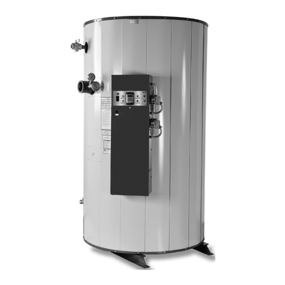
Page 5: Product Description
PRODUCT DESCRIPTION Component, Controls and Connection Locations (Locations May Vary) 34-55 08/14... -
Page 6: Boiler Installation
BOILER INSTALLATION 3.1 Checking Equipment Before You Install Inspect the unit completely upon receipt from the freight carrier before signing the bill of lading. Inspect the appliance and all accompanying parts for signs of impact or mishandling. Verify the total number of pieces shown on packing slips with those actually received. -
Page 7: General Piping Guidelines
GENERAL PIPING GUIDELINES Consult factory for piping of hybrid boiler systems that contain both condensing and non-condensing boilers. 4.1 Inlet and Outlet Connections The connection to the unit marked “Inlet” on the header connects to the return from the system (water to be heated). The connection on the header marked “Outlet”... -
Page 8: Filling The Boiler
4.4 Filling The Boiler Fill the system with water. To be sure that the unit is not “air bound,” open the relief valve. Leave the valve open until a steady flow of water is observed. Close valve and complete filling the system. In hard water areas, water treatment should be used to reduce introduction of minerals into the system. -
Page 9: Gas Supply Piping
GAS SUPPLY AND PIPING Verify that the type of gas specified on rating plate is supplied to the unit. This unit is orificed for operation up to 2000 feet altitude. Appliance btuh output derates 4% per 1000 feet elevation above sea level. Consult Factory for installations above 2000 feet elevation. -
Page 10: Appliance Isolation During Gas Supply Piping Pressure Test
MULTIPLE UNIT INSTALLATIONS GAS PIPING SIZE CHART Maximum Capacity of Pipe in Thousands of BTU’s per hour for gas pressures of 14 Inches Water Column (0.5 PSIG) or less and a pressure drop of 0.05 Inch Water Column (Based on NAT GAS, 1025BTU’s per Cubic Foot of Gas and 0.60 Specific Gravity). -
Page 11: Gas Control Trains
5.7 Gas Control Trains All models include gas control trains with the following components: main gas cock, a dual safety valve, proportionator regulator and a final manual shutoff valve with the manifold pressure tap on the side of the valve. CAUTION: Do not adjust or remove any screws or bolts on gas train control components which are sealed with a red or blue colored compound. -
Page 12: Remote Combustion Air Cap
A UL Listed air intake termination cap is available from Riverside Hydronics and may have shipped with the boiler as a purchased option. 6.4 Vertical or Horizontal Remote Air Duct Termination •... -
Page 13: Venting
(for attachment of the vent connector to the boiler vent connection) sized to match the required Category I vent diameter, must be obtained from Riverside Hydronics. Attach the properly sized vent increaser to the boiler vent connection with three sheet metal screws. A properly installed and adjusted barometric damper helps stabilize draft and regulate high updraft. -
Page 14: Category Iii Or Iv Venting
WARNING: Do not combine appliances utilizing Category I or Category II venting into the same vent system with appliances utilizing Category III or Category IV venting. This could cause unsafe operation and the potential for poisonous carbon monoxide to enter occupied areas. Such improper installation can cause property damage, personal injury, exposure to hazardous materials or death. -
Page 15: Maximum Category Iii Or Category Iv Vent Length
7.3.1 Maximum Category III or Category IV Vent Length (Equivalent Length) If a vertical or horizontal Category III or Category IV vent system is used with this appliance, the maximum length of field supplied venting is shown in the chart below titled Maximum Category III – Category IV Vent Equivalent Length. Maximum Category III –... -
Page 16: Combining Category Iii Or Category Iv Vents
9. A vertical vent must exhaust outside the building at least 3 feet (0.91m) above the point of the exit and at least 2 feet (0.61 m) above the highest point of the roof within a 10-foot (3.05 m) radius of the termination. 10. -
Page 17: Electronic Low Water Cut-Off
CAUTION: Do not install a reducing coupling, valve or other restriction in the relief valve(s) discharge line. The discharge line shall allow complete drainage of the valve and line. Relief valves should be manually operated at least once a year. WARNING: To prevent burns caused by hot water discharge and water damage, pipe the discharge from the relief valve to a suitable floor drain for disposal when relief occurs. -
Page 18: Temptrac Controller Panel
TEMPTRAC™ ELECTRONIC CONTROLLER PANEL 9.1 Principle Of Operation The boiler operates to satisfy the setpoint of the TempTrac digital control whose sensor is located in the return line of a Hydronic system. Demand (flow) will typically create a drop in temperature, thus activating the Centauri to add heat to the system. -
Page 19: Modulation Firing Sequence
9.5 Modulating Firing Sequence The boiler is fully modulating and initiates combustion at the lowest firing rate. It will modulate between this lowest possible rate and full rate as the boiler loop temperature rises and falls in relation to the operating set point. The Parameters involved with the modulation control sequence are St1, Hy1 St4, and SR. -
Page 20: To View The Setpoint
• C to D: Once modulation is established, the sensed loop temperature can fluctuate between 155°F and 145°F (between St4 and SR). The firing rate increases or decreases proportionately between 100% and low fire, depending upon the temperature sensed in the return loop. Temperature rise in the heat exchanger varies accordingly, 45°... -
Page 21: Led Display Alarm Messages
9.9 LED Display Alarm Messages Alarm messages are displayed in t upper LED readout and alternate with the default display. An alarm LED ICON is also illuminated. (See TempTrac User Manual 34-80 for full description.) ALARM RECOMMENDED CAUSE RESULTS OF ALARM CONDITION MESSAGE ACTION Inlet temperature sensor is not connected or... -
Page 22: Boiler Control Interface
BOILER CONTROL INTERFACE A terminal strip for the remote connection is located behind the hinged control panel at the top of the cabinet and is accessed by removing the bottom cover and then removing the screws at the top of the hinged cover. 10.1 If BMS/BAS provides remote on/off control directly to each boiler but allows boiler to control modulation on its own: •... -
Page 23: Outdoor Reset
22-gage, multi-strand copper wire into the thermister coil. (Thermister probe should be protected with suitable outdoor cover.) 10.6 Riverside Hydronics® ONTRAC® Boiler Management System (BMS) The OnTrac is a separate multiple boiler control designed to coordinate the operation of multiple boilers using TempTrac controls. -
Page 24: Bas Protocol Gateway
The standard protocol between the OnTrac and the BAS is Modbus TCP/IP. A gateway will be required to communicate with the BAS if it uses a different protocol. Riverside Hydronics offers pre-mapped gateways that support BACnet MSTP, BACnet IP, Lonworks or Johnson Controls N2. Consult factory for other protocols. (For a general overview of the application of this gateway, refer to Setup Manual #34-525.) - Page 25 The Delay-On (Low Fire Hold) Relay and the Gas Safety Valves are energized. During TFI the flame safeguard control will monitor the flame using flame rectification through the hot surface igniter. If the flame control senses the presence of flame before the end of the TFI period, the igniter will be de- energized and the flame control will continue to monitor the flame, through the igniter, until the operating thermostat ends the call for heat condition.
-
Page 26: Initial Startup
INITIAL STARTUP 12.1 Initial Startup Requirements Installation should be complete prior to performing initial startup; and the startup must be complete prior to placing the boiler into service. Starting the boiler without proper piping, combustion air, venting or electrical systems can be dangerous and may void the product warranty. - Page 27 Reattach the manometer to the gas train manual shutoff valve at the burner and record the measured gas pressure in inches of water column (W.C.). Measure gas pressure again after 15 minutes. If gas pressure has increased 0.5" W.C. or more, the gas leak must be isolated to one or more of the operating gas valves.
- Page 28 CAUTION: If at any point of the modulation range, carbon monoxide is in excess of 300ppm, contact Riverside Hydronics customer service for assistance. Enable or reconnect any BMS/BAS or OnTrac boiler control interface removed prior to the setup and adjustment of each boiler.
- Page 29 VALVE ORIFICE ADJUSTMENT DUAL SAFETY SHUTOFF VALVE AND REGULATOR REGULATOR ADJUSTMENT MANIFOLD PRESSURE Gas Train Illustration for Centauri Models 250 through 500 REGULATOR VALVE ORIFICE ADJUSTMENT ADJUSTMENT LOW PRESSURE GAS SWITCH DUAL SAFETY SHUTOFF VALVE HIGH GAS PRESSURE SWITCH MANIFOLD PRESSURE Gas Train Illustration for Centauri Models 650 through 2200 34-55 08/14...
-
Page 30: Troubleshooting Guide
TROUBLESHOOTING GUIDE Problem Probable Cause Corrective Action Check fuse and/or circuit breaker. Check voltage at Power Supply 120/24V step-down transformer. On-Off Switch Check if On-Off switch is lighted Check that the operating temperature control is set Temperature Control higher than the temperature of the boiler. Check for bad ground or bad control. -
Page 31: Replacement Parts
14 REPLACEMENT PARTS REPLACEMENT PARTS 34-55 08/14... -
Page 32: Control Panel
14.1 Control Panel 34-55 08/14... - Page 33 14.2 Control Panel Components (Optional components may not be included) Key No. Part No. Description Qty. 101947 CONTROL, HOT SURFACE IGNITION FENWAL #35-679652-551 24V 104796 CONTROL, TEMPERATURE TEMPTRAC #102920 REV A 115747 DRIVE, VARIABLE FREQUENCY AC BALDOR #VS1-ST11P5-0T 5613 FUSE HOLDER, PANEL TYPE #HTB-28I 5742 FUSE, MDA 15 AMP BUSS 250V NO SUBSTITUTE 113915...
- Page 34 14.3 Burner Assembly 34-55 08/14...
- Page 35 14.4 Burner Assembly Components Optional components may not be included) Key No. Qty. Part No. Description 111876 BLOWER, FASCO #70430069 SEE BOM ASSY, BULKHEAD REFRACTORY SEE BOM BURNER, METAL PUNCHED 114513 SPACER, NYLON 1/4 ID X 1/2 OD X 11/16 MCMASTER C 115248 ASSY, INTAKE GAS AIR 7 OD X 1 NPT 3494...
-
Page 36: Periodic Maintenance
5 & 6 below. All gaskets on disassembled components must be replaced on reassembly with exact, Factory Authorized, ® replacement parts only. Gasket kits are available from your Riverside Hydronics Representative or by ®... - Page 37 All replacement parts are available through your Riverside Hydronics Dealer. If you need assistance identifying or contacting your local dealer, you may contact Riverside Hydronics directly at the address and telephone number located on the first and last page of this manual.
-
Page 38: Recommended Maintenance Schedule
RECOMMENDED MAINTENANCE SCHEDULE Annual Maintenance a. Check all joints and pipe connections for tightness, corrosion or deterioration. b. Check the electronic-ignition system for quick ignition and a proper flame signal. c. Check all safety controls including thermostats for proper operation. d. - Page 39 NOTES: 34-55 08/14...
- Page 40 MODEL NUMBER: SERIAL NUMBER: INSTALLATION DATE: , LLC • 990 Haltom Road • Ft. Worth, TX 76117 • 1‐800‐990‐5918 • www.riversidehydronics.com Riverside Hydronics 34-55 08/14...
Need help?
Do you have a question about the VT.3 400 WB 125A-IF and is the answer not in the manual?
Questions and answers