Table of Contents
Advertisement
INSTALLATION & MAINTENANCE MANUAL
MODELS (400, 500, 600, 650, 700, 750, 800) WB 130 A-CBM
Installation and service must be performed by a qualified service installer, service agency or the gas supplier.
IMPORTANT:
THIS
MANUAL
MAINTENANCE OF THIS EQUIPMENT. READ AND FOLLOW THE INFORMATION IN THIS MANUAL AND ALL OTHER
PROVIDED INSTRUCTIONS, LABELS AND MARKINGS BEFORE INSTALLING, OPERATING OR SERVICING THIS UNIT.
TO THE INSTALLER: After installation, these instructions must be given to the equipment user or left near the appliance.
SPECIAL INSTRUCTIONS TO THE OWNER: Retain this manual for future reference. These instructions contain
important information that will help you in maintaining and operating this appliance.
®
Riverside Hydronics
, LLC
3220 Galvez Ave.
Fort Worth, Texas 76111
1-800-990-5918l
www.riversidehydronics.com
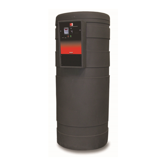
M3 CONDENSING WATER BOILER
CONTAINS
INFORMATION
REQUIRED
FOR
INSTALLATION,
OPERATION
AND
34-1115 12/15
Advertisement
Table of Contents

Related Manuals for Riverside Hydronics 400


Summary of Contents for Riverside Hydronics 400
- Page 1 M3 CONDENSING WATER BOILER INSTALLATION & MAINTENANCE MANUAL MODELS (400, 500, 600, 650, 700, 750, 800) WB 130 A-CBM Installation and service must be performed by a qualified service installer, service agency or the gas supplier. IMPORTANT: THIS MANUAL CONTAINS...
-
Page 2: Table Of Contents
M3 CONDENSING WATER BOILER TABLE OF CONTENTS Safety Considerations Product Description Boiler Installation Checking Equipment Before You Install Codes Electrical Requirements Handling and Locating the Boiler Clearances to Combustible Surfaces Service Clearances Other Codes and Regulatory Clearances and Requirements General Piping Guidelines Supply and Return Connections Sensor Locations and Thermal Well Filler the boiler... - Page 3 M3 CONDENSING WATER BOILER Operating and Safety Controls Pressure Relief Valve(s) Electronic Low Water Cut-off Operating Temperature Control High Water Temperature Limit Controls TEMPTRAC Electronic Controller Panel 10.1 Principal of Operation 10.2 Upper LED Readout 10.3 Lower LED Readout 10.4 Control Buttons 10.5 To View the Setpoint 10.6 To Change the Setpoint 10.7 To Lock and Unlock the Keyboard...
-
Page 4: Safety Considerations
M3 CONDENSING WATER BOILER SAFETY CONSIDERATIONS WARNING: If the information in the supplied manual(s) is not followed exactly, a fire, explosion or exposure to hazardous materials may result, causing property damage, personal injury or death. AVERTISSEMENT. Assurez-vous de bien suivre les instructions données dans cette notice pour réduire au minimum le risque d’incendie ou d’explosion ou pour éviter tout dommage matérial, toute blessure ou la mort FOR YOUR SAFETY •... - Page 5 M3 CONDENSING WATER BOILER PRODUCT SAFETY INFORMATION REFRACTORY CERAMIC FIBER PRODUCT WITH CRYSTALLINE SILICA WARNING: This product contains or may come to contain crystalline silica, which has been identified by the International Agency for Research on Cancer (IARC) as carcinogenic to humans. This product also contains refractory ceramic fibers, which have been identified by the IARC as possibly carcinogenic to humans.
-
Page 6: Product Description
M3 CONDENSING WATER BOILER PRODUCT DESCRIPTION Component, Controls and Connection Locations (Locations May Vary) 34-1115 12/15... -
Page 7: Boiler Installation
M3 CONDENSING WATER BOILER BOILER INSTALLATION 3.1 Checking Equipment Before You Install • Inspect the unit completely upon receipt from the freight carrier before signing the bill of lading. Inspect the appliance and all accompanying parts for signs of impact or mishandling. Verify the total number of pieces shown on packing slips with those actually received. -
Page 8: Clearances To Combustible Surfaces
M3 CONDENSING WATER BOILER 8. Use the following diagram to locate anchors or attachment points, when connecting the boiler to the floor. Typical concrete anchors: 5/16” x 1-3/4” double expansion shields. Anchoring Attachment Points for Connection to Floor 3.5 Clearances To Combustible Surfaces The minimum clearance to combustible material is 15”... -
Page 9: General Piping Guidelines
M3 CONDENSING WATER BOILER GENERAL PIPING GUIDELINES 4.1 Supply and Return Connections 1. Connect the boiler system return piping (water to be heated) to the “Return” fitting located near the bottom and rear of the boiler. 2. Connect the system supply piping (hot water out of the unit)) to the “Supply” fitting located and accessed at the top of the boiler. - Page 10 M3 CONDENSING WATER BOILER Example of a Multi Boiler, Primary Only Installation Example of a Multi Boiler, Primary/Secondary Only Installation 34-1115 12/15...
-
Page 11: Sensor Locations And Thermal Well
M3 CONDENSING WATER BOILER 4.2 Sensor Locations and Thermal Well The boiler uses an operating sensor and a monitoring sensor. One sensor is located in the thermal well in the upper portion of the boiler water tank. A second sensor for use external to the boiler is coiled and located in the control enclosure along with the Sensor Thermal Well. -
Page 12: Condensate Drain, Trap & Disposal
An optional, field installed, Condensate Neutralization System is available from the factory. Connect a condensate drain line or the Riverside Hydronics® Condensate Neutralization System to the barbed hose connection, sized for 1/2" ID heavy wall Vinyl tubing rated for 170ºF or higher, located at the end of the condensate trap. -
Page 13: Condensate Neutralization System (Optional)
The condensate neutralizer reduces or avoids the need for separate chemical treatment or dilution using substantial quantities of tap water. Contact your local Riverside Hydronics® representative to obtain a Condensate Neutralization System and follow the instructions included for assembly and connection. -
Page 14: Gas Supply And Piping
M3 CONDENSING WATER BOILER GAS SUPPLY AND PIPING Verify the type of gas specified on rating plate is supplied to the unit. This unit is orificed for operation up to 2000 feet altitude. Appliance Btu/h input derates 4% per 1000 feet elevation above sea level. Consult Factory for installations above 2000 feet elevation. -
Page 15: Appliance Isolation During Gas Supply Piping Pressure Test
M3 CONDENSING WATER BOILER Use the following table to determine the possible pipe size based on distance from gas meter for a Single Unit Installation using Schedule 40 Metallic Gas Pipe.* SINGLE UNIT INSTALLATION – POSSIBLE SCHEDULE 40 METALLIC GAS PIPE SIZE* Distance from meter in equivalent feet of schedule 40 metallic gas pipe.* Based on inlet pressure less than 2 psi, specific gravity of 0.60 and a pressure drop of 0.5 in. -
Page 16: Combustion And Ventilation Air
M3 CONDENSING WATER BOILER 5. Install a manual main gas shutoff valve on the gas supply piping connected to the appliance to isolate the burner and gas train from the main supply gas in compliance with NFPA 54 National Fuel Gas Code and most local Codes. -
Page 17: Maximum Allowed Remote Combustion Air Inlet Length
Maximum Air Inlet Duct Equivalent Length. Use metal tape or RTV sealant to seal each pipe joint. Maximum Air Inlet Duct Equivalent Length 4” 4” 6” Duct 8” Duct Duct Size (Model 400 Only) (Model 500 Only) (All Models) (All Models) 60 eq. feet Max Equivalent Length 100 eq. feet 150 eq. -
Page 18: Vertical Or Horizontal Remote Air Duct Termination
Hydronics.com/vent-design.html. Before operation of a combined remote air ducting system, all of the duct design firm’s system installation and operation requirements must be in place, their instructions followed and the system must be properly maintained. -
Page 19: Optional Filter Box For Dusty Or Dirty Combustion Air
M3 CONDENSING WATER BOILER 7.6 Optional Filter Box for Dusty or Dirty Combustion Air The field installed optional air inlet filter box must be attached to the combustion air inlet on any appliance located where it is exposed to dusty, dirty or lint filled combustion air. Replace the filter on a 3 to 6 month schedule, or more often, based on severity of contamination. -
Page 20: Venting
M3 CONDENSING WATER BOILER VENTING All M3 models use the positive pressure generated by the burner system blower to push combustion products out of the vent. Since the vent system is under positive pressure and must be capable of containing condensate, it must be constructed using schedule 40 solid PVC or CPVC pipe or using a Polypropylene or Stainless Steel venting system (single or double wall) listed by ETL, UL, ULC or CSA for Category IV positive pressure gas appliance venting. -
Page 21: Vent Installation - General
The maximum length of field supplied Category IV vent is shown in the chart below: Maximum Vent Length in Equivalent Feet 4" 6" Vent 8" Vent Vent Size (Use only on Models 400, 500 ) (All Models) (All Models) Max Equivalent Length 100 eq. feet 150 eq. feet 200 eq. -
Page 22: Vertical Or Horizontal Vent Termination
M3 CONDENSING WATER BOILER 8.2.2 Vertical or Horizontal Vent Termination: 1. The vent terminal must have a minimum clearance of 4 feet (1.22 m) horizontally from, and in no case be located above or below, unless a 4 foot (1.22 m) horizontal distance is maintained from electric meters, gas meters, regulators and relief equipment. -
Page 23: Connecting To An Existing Vent System
M3 CONDENSING WATER BOILER 8.2.4 Connecting to an Existing Vent System Do not connect the M3 to an existing vent system, until it has been confirmed the existing vent system complies with all requirements for a new vent system. A venting system in full compliance with the instructions provided in this manual is required for safe and reliable operation of the M3. -
Page 24: Cpvc Vent Installation
M3 CONDENSING WATER BOILER 8.4 CPVC Vent Installation Follow the instructions below for installing schedule 40 solid CPVC venting The stainless steel vent connection located near the rear of the boiler is 5-7/8” O.D., to accept 6 inch I.D. schedule 40 CPVC pipe. -
Page 25: Operating And Safety Controls
M3 CONDENSING WATER BOILER Follow the ETL, UL, ULC or CSA listed Polypropylene or listed single or double wall Stainless Steel, Category 4 positive pressure gas appliance vent system manufacturer’s instructions for installing, sealing, supporting and terminating their vent system. Do not insulate plastic vent pipe. Support the venting system following the venting system manufacturer’s installation instructions. -
Page 26: Operating Temperature Control
M3 CONDENSING WATER BOILER WARNING: Turn off all electrical service to the appliance when accessing the limit or other controls located inside the control cabinet or inside the burner vestibule inside the top of the appliance. Close and fasten the control cabinet and burner vestibule cover before restoring electrical service to the appliance. -
Page 27: Temptrac Electronic Controller Panel
M3 CONDENSING WATER BOILER TEMPTRAC™ Electronic Controller Panel 10.1 Principle Of Operation The boiler operates to satisfy the setpoint of the TempTrac digital control whose operating sensor is located near the top of the boiler tank, or in the return line of a Hydronic system, depending on the application. Demand (flow) will typically create a drop in temperature, thus activating the boiler to add heat to the hot water supply. -
Page 28: To View The Setpoint
M3 CONDENSING WATER BOILER 10.5 To View the Setpoint • Push and release the SET key to see the set point value. • To return to normal display, press SET + UP or wait 15 seconds without pressing any key. 10.6 To Change the Setpoint •... -
Page 29: Led Display Alarm Messages
M3 CONDENSING WATER BOILER 10.9 LED Display Alarm Messages Alarm messages are displayed in the upper LED readout and alternate with the default display. An alarm LED ICONs also illuminated. ALARM RECOMMENDED CAUSE RESULTS OF ALARM CONDITION MESSAGE ACTION Return temperature sensor is not connected or is Check wiring and sensor “P1”... -
Page 30: Remote Connections - Terminal Strip
RTU. The standard protocol between the OnTrac and the BAS is Modbus TCP/IP. A gateway will be required to ® communicate with the BAS if it uses a different protocol. Riverside Hydronics offers pre-mapped gateways that support BACnet MSTP, BACnet IP, Lonworks or Johnson Controls N2. Consult factory for other protocols. (For a general overview of the application of this gateway, refer to Setup Manual #34-525.) -
Page 31: Connecting Isolation Valves
M3 CONDENSING WATER BOILER L1-L2: Used for incoming 120VAC power supply connection. Terminal L1 is the HOT terminal and L2 is NEUTRAL. See the product catalog or specification document for circuit ampacity rating. R1-R2: Used to activate / de-activate boiler from remote master control. When switching this low current circuit, a relay with gold plated contacts or the use of two relay contacts in parallel must be used. - Page 32 M3 CONDENSING WATER BOILER 4. Call For Heat - If the TempTrac operating control senses a call-for-heat condition and the previous safety devices are energized the following sequence will begin: a. The enable contacts for the VFD are energized for the modulating burner models or the blower contacts close for the fixed input burner models.
-
Page 33: Initial Startup
M3 CONDENSING WATER BOILER INITIAL STARTUP 13.1 Initial Startup Requirements Installation must be complete prior to the required factory authorized initial startup. The factory authorized startup must be complete prior to placing the boiler into service. Starting the boiler without proper piping, combustion air, venting or electrical connections or control settings can be dangerous and may void the product warranty. - Page 34 M3 CONDENSING WATER BOILER 3. Be sure all connections into the tank are tight, as leaks at tank fittings will damage the insulation. 4. CAUTION: Conduct the following gas train leakage test before start-up, at annual intervals and prior to investigating the cause of any reported occurrences of delayed ignition.
- Page 35 All models are adjusted as follows: With the burner firing and adjusted to Low Fire, adjust the regulator screw clockwise (counter clockwise for the 400, requires Allen wrench) to increase gas flow or counter clockwise to decrease flow. The desired CO in the combustion products must be between 8.5 and 9.5% for natural gas, 9.5% to 10.5% for LP gas.
- Page 36 M3 CONDENSING WATER BOILER Gas Train Illustration for Model 400 Gas Train Illustration for Models 500 through 800 (Optional components may not be shown) 34-1115 12/15...
- Page 37 M3 CONDENSING WATER BOILER Alternate Gas Train Illustration for Models 500 through 800 (Optional components may not be shown) 34-1115 12/15...
-
Page 38: Troubleshooting Guide
M3 CONDENSING WATER BOILER TROUBLESHOOTING GUIDE Problem Probable Cause Corrective Action Power Supply Check fuse and/or circuit breaker. Check if On-Off switch is illuminated when on. If not check On-Off Switch panel fuse or incoming power. Check that the operating temperature control is set higher Temperature Control than the temperature of the boiler. -
Page 39: Replacement Parts
M3 CONDENSING WATER BOILER REPLACEMENT PARTS 15.1 Burner Assemblies Burner Assembly Illustration for Model 400 (Optional components may not be shown) 34-1115 12/15... - Page 40 M3 CONDENSING WATER BOILER Burner Assembly Illustration for Models 500 through 800 (Optional components may not be shown) 34-1115 12/15...
-
Page 41: Control Panel Enclosure Component Layout And Replacement Pn's
M3 CONDENSING WATER BOILER 15.2 Control Panel Enclosure Component Layout and Replacement PN’s LIST OF MATERIALS ITEM PART NO. DESCRIPTION CONTROL PANEL COMPONENTS see next TempTrac Control page 70573 Reset / Test Switch N.C. Momentary 122342 Indicating Light 124016 Main Decal 121323 Thumb Screw 1/4-20 5613... -
Page 42: Replacement Temptrac Kit Part
M3 CONDENSING WATER BOILER 15.3 Replacement TempTrac Kit Part List Outdoor Temptrac Input Venting Material Used Reset Kit PN 400 MBH Stainless Steel 124567 500 MBH Stainless Steel 124568 600 MBH Stainless Steel 124569 650 MBH Stainless Steel 124564 700-800 MBH... -
Page 43: Component Wiring And Conduit Routing Details
M3 CONDENSING WATER BOILER 15.4 Component Wiring and Conduit Routing Details 34-1115 12/15... -
Page 44: Periodic Maintenance
4, 5 & 6 below. 4. All gaskets on disassembled components must be replaced on reassembly with exact, Factory Authorized, ® replacement parts only. Gasket kits are available from your RIVERSIDE HYDRONICS Representative or by ®... - Page 45 12. All replacement parts are available through your RIVERSIDE HYDRONICS Dealer. If you need assistance ® identifying or contacting your local dealer, you may contact RIVERSIDE HYDRONICS , LLC directly at the address and telephone number located on the first and last page of this manual.
-
Page 46: Recommended Maintenance Schedule
M3 CONDENSING WATER BOILER RECOMMENDED MAINTENANCE SCHEDULE Regular service by a qualified service agency and routine maintenance must be performed to ensure safe, reliable and efficient operation. Yearly (Beginning of Each Heating Season) Schedule annual service call by qualified service agency. 1. - Page 47 M3 CONDENSING WATER BOILER 34-1115 12/15...
- Page 48 M3 CONDENSING WATER BOILER ® Since RIVERSIDE HYDRONICS , LLC cannot control the use of the appliance, water conditions, or maintenance, the warranty on the heat exchanger does not cover poor performance, structural failure, or leaking due to an excessive accumulation of precipitants.
Need help?
Do you have a question about the 400 and is the answer not in the manual?
Questions and answers