Table of Contents
Advertisement
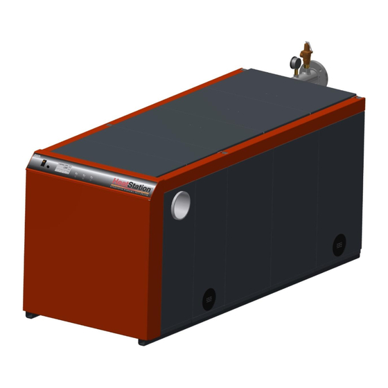
HeatStation™ CONDENSING WATER BOILER
INSTALLATION & MAINTENANCE MANUAL
MODELS HS (1000, 1250, 1500, 1750, 2000)
Installation and service must be performed by a qualified service installer, service agency or the gas supplier.
IMPORTANT: THIS MANUAL CONTAINS INFORMATION REQUIRED FOR INSTALLATION, OPERATION AND MAINTENANCE
OF THIS EQUIPMENT. READ AND FOLLOW THE INFORMATION IN THIS MANUAL AND ALL OTHER PROVIDED
INSTRUCTIONS, LABELS AND MARKINGS BEFORE INSTALLING, OPERATING OR SERVICING THIS UNIT.
TO THE INSTALLER: After installation, these instructions must be given to the equipment user or left near the appliance.
SPECIAL INSTRUCTIONS TO THE OWNER: Retain this manual for future reference. These instructions contain important
information that will help you in maintaining and operating this appliance.
Riverside Hydronics®
3209 Galvez Avenue
Fort Worth, Texas 76111
1-800-990-5918
www.riversidehydronics.com
34-1161 05/17
Advertisement
Table of Contents
Troubleshooting

Related Manuals for Riverside Hydronics HeatStation HS 1000


Summary of Contents for Riverside Hydronics HeatStation HS 1000
- Page 1 TO THE INSTALLER: After installation, these instructions must be given to the equipment user or left near the appliance. SPECIAL INSTRUCTIONS TO THE OWNER: Retain this manual for future reference. These instructions contain important information that will help you in maintaining and operating this appliance. Riverside Hydronics® 3209 Galvez Avenue Fort Worth, Texas 76111 1-800-990-5918 www.riversidehydronics.com...
-
Page 2: Table Of Contents
HeatStation™ CONDENSING WATER BOILER TABLE OF CONTENTS Safety Considerations Product Descriptions Boiler Installation Checking Equipment Before You Install Codes Electrical Requirements Handling and Locating the Boiler Clearances to Combustible Surfaces Service Clearances Other Codes and Regulatory Clearances and Requirements General Piping Guidelines Supply and Return Connections Sensor Locations and Thermal Well Filling the Boiler... - Page 3 HeatStation™ CONDENSING WATER BOILER 10.2 Status Field Display 10.3 Operational Sequence Field Display 10.4 View Menu (Home Screen - Default Display) 10.5 Control System Menus 10.6 Selecting the Correct Applicationi Mode 10.7 Control Setting for Hydronic System Design 10.8 Selecting the Supply or Return Sensor for Single Boiler Primary Only System 10.9 Changing the Operating Target 10.10 Setting the Real Time Clock 10.11 Scheduled Setback...
-
Page 4: Safety Considerations
HeatStation™ CONDENSING WATER BOILER SAFETY CONSIDERATIONS WARNING: If the information in the supplied manual(s) is not followed exactly, a fire, explosion or exposure to hazardous materials may result, causing property damage, personal injury or death. AVERTISSEMENT. Assurez-vous de bien suivre les instructions données dans cette notice pour réduire au minimum le risque d’incendie ou d’explosion ou pour éviter tout dommage matérial, toute blessure ou la mort FOR YOUR SAFETY ... - Page 5 HeatStation™ CONDENSING WATER BOILER PRODUCT SAFETY INFORMATION REFRACTORY CERAMIC FIBER PRODUCT WITH CRYSTALLINE SILICA WARNING: This product contains or may come to contain crystalline silica, which has been identified by the International Agency for Research on Cancer (IARC) as carcinogenic to humans. This product also contains refractory ceramic fibers, which have been identified by the IARC as possibly carcinogenic to humans.
-
Page 6: Product Descriptions
HeatStation™ CONDENSING WATER BOILER PRODUCT DESCRIPTIONS Component, Controls and Connection Locations (Locations May Vary) Dimensional information for HS 1000, HS 1250, and HS 1500 34-1161 05/17... - Page 7 HeatStation™ CONDENSING WATER BOILER Dimensional information for HS 1750 and HS 2000 34-1161 05/17...
-
Page 8: Boiler Installation
HeatStation™ CONDENSING WATER BOILER BOILER INSTALLATION 3.1 Checking Equipment Before You Install Inspect the unit completely upon receipt from the freight carrier before signing the bill of lading. Inspect the appliance and all accompanying parts for signs of impact or mishandling. Verify the total number of pieces shown on packing slips with those actually received. -
Page 9: Service Clearances
HeatStation™ CONDENSING WATER BOILER back of the boiler. The HeatStation can be installed directly on a combustible floor, but not on carpet. Distance minimale aux matériaux combustibles est égale à zéro (0 cm) sur les haut, côtés et à l'arrière, avant les 61 cm et peut être installé... - Page 10 HeatStation™ CONDENSING WATER BOILER IMPORTANT: Do not use the plumbing connected to the appliance as a ground for welding or any other purpose. Example of a Single Boiler, Primary Only Installation Example of a Multi Boiler, Primary Only Installation 34-1161 05/17...
- Page 11 HeatStation™ CONDENSING WATER BOILER Example of a Single Boiler, Primary/Secondary Only Installation Example of a Multi Boiler, Primary/Secondary Only Installation 34-1161 05/17...
-
Page 12: Sensor Locations And Thermal Well
HeatStation™ CONDENSING WATER BOILER 4.2 Sensor Locations and Thermal Well The selection of the hydronic system design is explained in detail in Section 10 “Control Settings for Hydronic System Design”. The EOS control system on HeatStation comes configured for the Multi Boiler Primary/Secondary hydronic system. The system sensor will automatically be selected for system temperature regulation. -
Page 13: Condensate Drain, Trap & Disposal
HeatStation™ CONDENSING WATER BOILER CONDENSATE DRAIN, TRAP & DISPOSAL The HeatStation boiler produces a significant amount of condensate. The condensate drain is under slightly positive flue pressure; therefore the 1" CPVC condensate trap assembly supplied with the product must always be used. This trap is sized and designed to create a liquid barrier to prevent flue gases from escaping through the condensate drain into the installed space. -
Page 14: Condensate Neutralization System (Optional)
The condensate neutralizer reduces or avoids the need for separate chemical treatment or dilution using substantial quantities of tap water. Contact your local Riverside Hydronics representative to obtain a Condensate Neutralization System and follow the instructions included for assembly and connection. -
Page 15: Gas Supply And Piping
HeatStation™ CONDENSING WATER BOILER GAS SUPPLY AND PIPING Verify the type of gas specified on rating plate is supplied to the unit. This unit is orificed for operation up to 2000 feet altitude. Appliance Btu/h input derates 4% per 1000 feet elevation above sea level. Consult Factory for installations above 2000 feet elevation. -
Page 16: Appliance Isolation During Gas Supply Piping Pressure Test
HeatStation™ CONDENSING WATER BOILER Use the following table to determine the possible pipe size based on distance from gas meter for a Single Unit Installation using Schedule Metallic Gas Pipe.* SINGLE UNIT INSTALLATION SUGGESTED PIPE SIZE Maximum Capacity for Natural Gas* Equivalent Feet MBTU/HR Based on 0.5"... -
Page 17: Combustion And Ventilation Air
HeatStation™ CONDENSING WATER BOILER COMBUSTION AND VENTILATION AIR Provisions for adequate combustion and ventilation air to the mechanical room must be in accordance with Section “Air for Combustion and Ventilation” in the latest edition of the NFPA 54 National Fuel Gas Code, ANSI Z223.1 and/or CAN/CSA B149, Installation Codes or applicable provisions of the local building codes. -
Page 18: Maximum Allowed Remote Combustion Air Inlet Length
HeatStation™ CONDENSING WATER BOILER 7.2 Maximum Allowed Remote Combustion Air Inlet Length (Equivalent Length) A vertical or horizontal remote air inlet system can be connected to this appliance without modification. The maximum length of field supplied single wall pipe, such as galvanized ventilation pipe, is shown in the chart below titled Maximum Air Inlet Duct Equivalent Length. -
Page 19: Combining Remote Air Ducting
HeatStation™ CONDENSING WATER BOILER 7.5 Combining Remote Air Ducting Each boiler MUST have separate intake piping, unless the air inlet piping, exhaust duct and other system considerations have been fully evaluated and a combined duct system designed by one of the duct design firms identified a. -
Page 20: Venting
HeatStation™ CONDENSING WATER BOILER VENTING All HeatStation models use the positive pressure generated by the burner system blower to push combustion products out of the vent. Since the vent system is under positive pressure and must be capable of containing condensate, it must be constructed using schedule 40 solid PVC or CPVC pipe or using a Polypropylene or Stainless Steel venting system (single or double wall) listed by ETL, UL, ULC or CSA for Category IV positive pressure gas appliance venting. -
Page 21: Vent Installation - General
HeatStation™ CONDENSING WATER BOILER 8.2 Vent Installation – General The HeatStation boiler can be vented either vertically, through a ceiling or roof, or horizontally through a wall. The HeatStation boiler is a Category IV positive pressure gas appliance, so venting can be routed to the outdoors in any direction from the vent connection of the boiler, except down. -
Page 22: Vertical Or Horizontal Vent Termination
HeatStation™ CONDENSING WATER BOILER 8.2.2 Vertical or Horizontal Vent Termination 1. The vent terminal must have a minimum clearance of 4 feet (1.22 m) horizontally from, and in no case be located above or below, unless a 4 foot (1.22 m) horizontal distance is maintained from electric meters, gas meters, regulators and relief equipment. -
Page 23: Connecting To An Existing Vent System
HeatStation™ CONDENSING WATER BOILER 8.2.4 Connecting to an Existing Vent System Do not connect the HeatStation to an existing vent system, until it has been confirmed the existing vent system complies with all requirements for a new vent system. A venting system in full compliance with the instructions provided in this manual is required for safe and reliable operation of the HeatStation. -
Page 24: Cpvc Vent Installation
HeatStation™ CONDENSING WATER BOILER 8.4 CPVC Vent Installation Follow the instructions below for installing schedule 40 solid CPVC venting: The stainless steel vent connection located near the rear of the boiler is 8” I.D with an internal gasket and clamp. This connection will accept most 8 inch stainless or polypropylene venting. -
Page 25: Operating And Safety Controls
HeatStation™ CONDENSING WATER BOILER Seal the vent pipe at the point where it passes through a wall or roof following the venting system manufacturer’s installation instructions. For proper vent operation, attach the vent system’s termination following the listed venting system manufacturer’s installation instructions. -
Page 26: Operating Temperature Control
HeatStation™ CONDENSING WATER BOILER WARNING: Turn off all electrical service to the appliance when accessing the limit or other controls located inside the control cabinet or inside the burner vestibule inside the top of the appliance. Close and fasten the control cabinet and burner vestibule cover before restoring electrical service to the appliance. - Page 27 HeatStation™ CONDENSING WATER BOILER ELECTRONIC OPERATING SYSTEM (EOS) The HeatStation EOS consists of three components: The Platform Ignition Module (PIM), plug-in ID card and the Control Display (BTCII). The PIM is connected to the control display using an RJ485 patch cable. All communication between the PIM and control display as well as the power to the control display is through this cable.
-
Page 28: Touch Screen User Interface
HeatStation™ CONDENSING WATER BOILER 10.1 Touch Screen User Interface The touchscreen of the EOS provides one-touch access to view and adjust various Menu set points. The touchscreen displays Status Fields, Items, Boiler Output and Number Fields. It also contains buttons for navigation & adjustment, and the Home Button to access menu selections. -
Page 29: View Menu (Home Screen - Default Display)
HeatStation™ CONDENSING WATER BOILER 10.4 View Menu (Home Screen - Default Display) Menu Icon The CTRL TEMP is the operating temperature sensed at the control location. Home Button. Return to the ‘Home’ Screen from any menu. Press and hold for 3 seconds to access Indication of burner firing rate as the programming menus. -
Page 30: Control System Menus
HeatStation™ CONDENSING WATER BOILER 10.5 Control System Menus The control display has multiple access levels. System critical settings will not be available for adjustment. The settings which can be adjusted by the user will display UP and DOWN adjustment arrows on the right side of the display screen. -
Page 31: Control Setting For Hydronic System Design
HeatStation™ CONDENSING WATER BOILER 10.7 Control Setting for Hydronic System Design (USER Level Access) There are some basic settings which must be made before commissioning this boiler. These setting will allow the boiler to function within different types of hydronic systems. Section 4 provides illustrations and details the application of the Single Boiler Primary only, Multi Boiler Primary only with Isolation Valve and Primary/Secondary hydronics systems. -
Page 32: Setting The Real Time Clock
HeatStation™ CONDENSING WATER BOILER 10.10 Setting the Real Time Clock (User & Installer Level Access) The TIME MENU allows the user to program the time of day, the date and the year. A 12 or 24 hour time clock as well as daylight saving time can be selected. -
Page 33: Using The Manual Override Menu
HeatStation™ CONDENSING WATER BOILER 3. The 5-2 schedule type gives the user the ability to program a 2 or 4 EVENT/DAY but will also allow for one schedule to be followed Monday – Friday and then another Saturday and Sunday. 4. -
Page 34: Potentiometer (Operating Set Point For Standalone Operation)
HeatStation™ CONDENSING WATER BOILER 10.13 10.13 Potentiometer (Operating Set Point for Standalone Operation) The PIM ignition control will continue to operate the HeatStation to an internal setpoint (default is 140°F) should the touch screen control fail or communication between the two devices is interrupted. The internal set point can be adjusted using the potentiometer. - Page 35 HeatStation™ CONDENSING WATER BOILER The target temperature will be adjusted based on an internally calculated reset ratio. The calculations are as follows: The Outdoor Sensor (PVI part# 143612) should be wired to the PIM control terminal as illustrated below: Connect Outdoor Sensor to the ORD and GND terminals.
-
Page 36: Multiple Boiler Cascade System
HeatStation™ CONDENSING WATER BOILER 10.15 Multiple Boiler Cascade System (INSTaller level access) The Cascade function is intended to be used with any Multi Boiler installation. The EOS control system on HeatStation is capable of controlling 12 boilers in a cascade system. Cascading multiple boilers is important for a number of reasons. - Page 37 HeatStation™ CONDENSING WATER BOILER The following illustration shows how to establish a communication link between boilers: The tN4 and GND terminals are the communication point for the PIM. Terminal tN4 and GND should be connected in a daisy chain manner to each between each boiler.
-
Page 38: Ems Control
The on position will in turn select Manual Differential. This state should only be selected when advised by the Riverside Hydronics application specialist. 2. Switch #2 – This switch selects the type of EMS control. The OFF position (default) will adjust Target Temperature when EMS is enabled. -
Page 39: Using Tool Box Menu
HeatStation™ CONDENSING WATER BOILER 3. Switch #4 – Enables Pump Exercise. When enabled (ON position), the primary pump will cycle for 10 seconds every 72 hours, even with no heat demand, to help extend the life of the pumps. 4. Switch #5 – Enables the EMS function. See the Section on EMS Control. 5. -
Page 40: Communications And Diagnostics
HeatStation™ CONDENSING WATER BOILER COMMUNICATIONS AND DIAGNOSTICS 11.1 Indicators The PIM has three LED indicators to display operational status and to help diagnose system error conditions: Power: Green LED indicating the PIM module is receiving 24 VAC power. Alarm/Test: Amber LED which indicates the PIM is in Commission Test Mode or that a diagnostic alarm (fault) is present. -
Page 41: Replacing The Fuse
HeatStation™ CONDENSING WATER BOILER Indicates a problem with the supply temperature sensor, possibly a Boil OUT broken or shorted sensor wire or failed sensor. NOTE: The boiler supply sensor and the high limit sensor or located in the same probe body. Indicates a problem with the high limit temperature sensor, possibly a HI LIMIT broken or shorted sensor wire or failed sensor. -
Page 42: Remote Connections - Terminal Strip
HeatStation™ CONDENSING WATER BOILER The PIM determines its operating parameters by reading the identification code of an external plug-in ID card. The ID card is connected to the PIM at the J6 connector. NOTE: This ID card must be present for the PIM and appliance to operate. This card selects the proper settings in the PIM's memory for various appliance models. -
Page 43: Internal Component Terminal Functions And Primary Pump Control
Also used for motorized isolation valve relay. 120Vac. OPTION 1 – 2: Power to initiate DHW (Direct Hot Water) Pump. 120Vac. Do not attempt to power pump directly through this source. Contract Riverside Hydronics for more information. H1-H2: Water Flow Switch is connected here. -
Page 44: Sequence Of Operation
HeatStation™ CONDENSING WATER BOILER SEQUENCE OF OPERATION 1. Incoming 120VAC a. Full time power to the Main Control Switch. 2. Power On - When the main control switch is turned on power is applied to the fuse then: a. 120V is applied to the step-down transformer (24V), L.W.C.O, J12-6, J14-3, J14-5, L1 terminals and the control switch lamp. - Page 45 HeatStation™ CONDENSING WATER BOILER 5. Heat-Up - Following the pre-purge delay, the hot surface igniter will be energized: a. The flame control will send 120V to the hot surface igniter for approximately 20 seconds. b. The HSI Element proving current is verified. c.
-
Page 46: Initial Startup
HeatStation™ CONDENSING WATER BOILER 14 INITIAL STARTUP 14.1 Initial Startup Requirements Installation must be complete prior to performing initial startup; and the startup must be complete prior to placing the boiler into service. Starting the boiler without proper piping, combustion air, venting or electrical connections or control settings can be dangerous and may void the product warranty. - Page 47 HeatStation™ CONDENSING WATER BOILER Automation System during startup. Remember to reconnect the communication cable to the digital control display board after startup is complete. Visually check that all components are intact and no damage has occurred during transit and installation. ...
-
Page 48: Startup Procedure
4. Burner Combustion Adjustment WARNING: If at any point carbon monoxide is in excess of 200 ppm, contact Riverside Hydronics Customer Care for assistance. WARNING: Do not continue to operate the appliance with carbon monoxide levels above 200 ppm. Carbon monoxide is a colorless, odorless and poisonous gas that commonly results from gas combustion. - Page 49 HeatStation™ CONDENSING WATER BOILER With the burner firing, measure the flow gas pressure at the beginning of the gas train. If the inlet flow gas pressure for Natural Gas is equal to or greater than 3.5 inches water column, continue with the startup. If the inlet flow gas pressure drops below these minimum requirements, a supply gas volume or piping problem may exist and must be corrected before the startup can continue.
-
Page 50: Potentiometer
HeatStation™ CONDENSING WATER BOILER Gas Train Illustration for Model HS 14.7 Potentiometer (Adjusting the Setpoint) The PIM Ignition Control will continue to operate the Heatstation boiler at a 140 degree internal factory setpoint should the touch screen control fail, or communication between the two devices is interrupted. This internal setpoint can be adjusted using the potentiometer to maintain a different operating temperature under these circumstances if desired. -
Page 51: Troubleshooting Procedure
The LED will flash on for 1/10 second, then off for 2/5 second during a fault condition. The pause between fault codes is 8 seconds. If the problem is not addressed in this chapter or, if after performing the suggested actions, the problem persists, contact Riverside Hydronics Technical Support 1-800-990-5918. 34-1161 05/17... -
Page 52: General Troubleshooting
HeatStation™ CONDENSING WATER BOILER 15.1 General Troubleshooting Symptom Probable Cause Corrective Action Power Supply Check fuse and/or circuit breaker. Check if On-Off switch is illuminated when on. If not check panel On-Off Switch fuse or incoming power. Check that the operating temperature control is set higher than Temperature Control the temperature of the boiler. -
Page 53: Led Error Code Listing
HeatStation™ CONDENSING WATER BOILER 15.2 LED Error Code Listing The following table lists the errors detected by the Platform Ignition Module (PIM) control and the associated LED indications. Error Mode LED Code Recommended Troubleshooting Normal Operation Red LED Steady ON, Green Check that the proper ID card is securely connected. -
Page 54: Replacement Parts
HeatStation™ CONDENSING WATER BOILER REPLACEMENT PARTS 16.1 Blower & Burner Assembly (Optional components may not be shown) ITEM DESCRIPTION HS 1000 HS 1250 HS 1500 HS 1750 HS 2000 ASSY,TRANSITION BURNER/BLOWER 1000-1250 HS GRAY 127694 127694 ASSY,TRANSITION BURNER/BLOWER 1500-2000 HS GRAY 127695 127695 127695... -
Page 55: Control Panel Components
HeatStation™ CONDENSING WATER BOILER 16.2 Control Panel Components ITEM DESCRIPTION HS 1000 HS 1250 HS 1500 HS 1750 HS 2000 Digital Control Display HMI TEKMAR 126070 126070 126070 126070 126070 SWITCH, SPST N.C. MOMENTARY CONTACT SELECTA 70573 70573 70573 70573 70573 SWITCH, SPST N.O. -
Page 56: Gas Train Assembly
HeatStation™ CONDENSING WATER BOILER 16.3 Gas Train Assembly ITEM DESCRIPTION HS 1000 HS 1250 HS 1500 HS 1750 HS 2000 VALVE,GAS DUNGS MBC 120VAC 109884 109884 109884 109883 109883 VALVE,SHUTOFF GAS COMBU MODEL 52823 52823 52823 45327 45327 UNION, BLACK 1 5929 5929 5929... -
Page 57: Component Wiring Details
HeatStation™ CONDENSING WATER BOILER 16.4 Component Wiring Details 34-1161 05/17... -
Page 58: Periodic Maintenance
4, 5 & 6 below. 4. All gaskets on disassembled components must be replaced on reassembly with exact, Factory Authorized, replacement parts only. Gasket kits are available from your Riverside Hydronics Representative or by contacting Riverside Hydronics. - Page 59 9. When electrical controls are serviced or replaced, label all connections as they are removed, to know the proper placement on the replacement part. 10. All replacement parts are available through your Riverside Hydronics Dealer. If you need assistance identifying or contacting your local dealer, you may contact Riverside Hydronics directly at the address and telephone number located on the first and last page of this manual.
-
Page 60: Recommended Maintenance Schedule
HeatStation™ CONDENSING WATER BOILER RECOMMENDED MAINTENANCE SCHEDULE Regular service by a qualified service agency and routine maintenance must be performed to ensure safe, reliable and efficient operation. Yearly (Every 12 Months) Schedule annual service call by qualified service agency. 1. Check for piping leaks around pumps, relief valves, and boiler connections. Repair, if found. 2. - Page 61 HeatStation™ CONDENSING WATER BOILER 34-1161 05/17...
- Page 62 HeatStation™ CONDENSING WATER BOILER Since Riverside Hydronics cannot control the use of the appliance, water conditions, or maintenance, the warranty on the heat exchanger does not cover poor performance, structural failure, or leaking due to an excessive accumulation of scale.
Need help?
Do you have a question about the HeatStation HS 1000 and is the answer not in the manual?
Questions and answers