Table of Contents
Advertisement
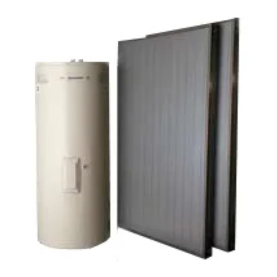
BSS250E-2 / BSS250-21-2 / BSS250-26-2
BSS300E-2 / BSS300-21-2 / BSS300-26-2
BSS400E-2 / BSS400-21-2 / BSS400-26-2
INSTALLATION AND USER
System Installation
Controller & Pump
Solar Panels
This solar hot water system must be installed in accordance with the manufacturer's installation
instructions, AS5601, AS3500.4. AS3000 wiring regulations (in New Zealand NZBC G12) and all Local
Building, Water and Gas fitting regulations.
To be installed and serviced only by an authorised person
This appliance is not suitable for use as a pool heater
Please see important note regarding tank on Page 15
The "authorised installing person" is responsible for:
1.
Correct commissioning of this system.
2.
Ensure units perform to the specifications stated on the rating label.
3..
Demonstrate operation of the system to the customer before leaving.
4.
Hand these instructions to customer.
Failure to install this system in accordance with these installation instructions may void warranty
Note: These instructions are subject to change, due to continuous product improvement.
19/07/2011
MODELS
Australia & New Zealand
HANDBOOK
Version 19
Gas solar booster
Solar Tank
Solar Wizard
Advertisement
Table of Contents

Related Manuals for Bosch BSS250E-2


Summary of Contents for Bosch BSS250E-2
- Page 1 MODELS BSS250E-2 / BSS250-21-2 / BSS250-26-2 BSS300E-2 / BSS300-21-2 / BSS300-26-2 BSS400E-2 / BSS400-21-2 / BSS400-26-2 Australia & New Zealand INSTALLATION AND USER HANDBOOK System Installation Gas solar booster Controller & Pump Solar Tank Solar Panels This solar hot water system must be installed in accordance with the manufacturer’s installation...
-
Page 2: Table Of Contents
INDEX Page Number Basic Solar Hot Water Layout 3 - 4 Introduction Basic Installation steps 5 - 6 Contents Solar Collectors 8- 14 Solar Tank and Components 15-21 Electric Boosting 22-23 Solar Tank Specifications Gas Boosting 25-32 Controller & Pump 32-42 Commissioning Home Owners Guide &... - Page 3 BASIC SOLAR TANK AND COMPONENT LAYOUT 250L, 300L & 400L Gas Solar Booster boosted Solar Set to 75°c Solar panel sensor Solar return from panel Isolating Non-Return valve Flow to panels valves Solar storage tank Tank outlet Hot water supply to fixtures (Temperature control valve Must be fitted) piping...
- Page 4 BASIC PANEL LAYOUT 1,2 & 3 PANEL Auto Air vent Custom fitting to suit top left of Must be upright and collector with inbuilt sensor socket ensure vent cap is and connection for Air Relief Valve open *NOTE: All pipes and fittings must be lagged with pipe insulation to prevent heat loss.
-
Page 5: Introduction
INTRODUCTION The following instructions are for the installation of a Split solar hot water system/s, being the panels are mounted on the roof of the dwelling and the solar tank is located either internally or externally at ground level. Where a gas solar booster is to be used, it should be mounted adjacent (In an external location) to the solar tank. - Page 6 Pump & Controller (See page 30 - 39 for more detail) Pump and controller is securely mounted on a wall to the side of the tank (within 500mm of the tank.) The power supply lead to the pump and controller is 1500mm in length.
-
Page 7: Contents
Clean up site Hand the customer the operating instructions Explain the system operation Answer any customer queries. CONTENTS Your „Solar Wizard‟ Solar hot water system is supplied with the following components: Parts List Item Description storage tank 1 or 2 solar collector 2610mm (L) x 38mm (W) x 25mm (H) x 1.6mm (T) Upper mounting rail... -
Page 8: Solar Collectors
SOLAR COLLECTORS The solar panels absorber material is Black painted copper fins, the outer casing is constructed from corrosion resistant brown anodized aluminum and the glass is low-ironed prismatic glass. Width (mm) Length (mm) Weight empty (Kg) Weight Full (Kg) 1200 2040 SOLAR COLLECTOR LOCATION... - Page 9 Conduct an inspection of the intendant installation position and ensure that the panels can be fitted in this position prior to commencing any work. 1. Position the lower bracket on the roof ensuring there is sufficient room to fit the panels. 2.
- Page 10 16. Replace tiles 17. Make all water connections, fit all valves and components as per the solar layout diagram contained in these instructions. 18. Note: The panels should be covered fully to prevent the panels heating up to temperatures that have potential to cause damage or injury during system fill or commissioning.
- Page 11 8. Remove the panels, align the upper bracket with the marked line and fix the panel to the steel roof using roofing screws or rivets. 9. Weather proof screw heads and rivets with silicone sealant. 10. Refit the panels between the brackets. 11.
- Page 12 8. Position the mounting rail and insert the screws through the rail and into the roof batten, place a rubber washer as a seal between the roof surface and the mounting rail, then evenly tighten the screws. Do not over tighten and break a tile. NOTE: ensure a rubber sealing washer is placed between the rail and the roof surface for each screw hole, to provide adequate sealing of the screw hole from water ingress.
- Page 13 header pipe, diagonally opposite from the inlet and returns to the “Solar Return” on the tank. 18. Install the air bleed valve onto the outlet of the panels at the top Left hand corner of the panels. 19. NOTE: The air bleed valve needs to be commissioned and checked to ensure the valve top is opened and that when the pump operates the valve seals properly.
- Page 14 Upon completion of the water heater installation, check the panels and associated plumbing for leaks while the pump is operating. COLLECTOR INSTALLATION IN CYCLONE AREAS The solar panels are SUITABLE for installation in cyclonic locations when installed with an additional rail mounting and brackets to provide the required additional fixing to the roof frame. This ensures conformance with AS1170.2.
-
Page 15: Solar Tank And Components
SOLAR TANK Important Note: Please ensure you remove plastic transit plugs from tank and replace with brass plugs supplied with panel fitting kit (These plastic plugs will not withstand solar water temperature and will melt causing leakage from tank). Solar tanks are available in 250 Litre, 300 & 400 Litres capacities. All three tanks have cold water inlet and hot water outlets on both the left and right hand sides of the tanks for convenience. - Page 16 INSTALLATION – STORAGE TANK COMPLIANCE WITH STANDARDS The installation must be performed by an Authorised Persons and comply with the requirements of AS/NZS 3500.4, AS/NZS 3000 in New Zealand NZBC G12 and all local codes and regulatory authority requirements. It is recommended the solar storage tank be installed at ground or floor level.
- Page 17 Adequate provision must be made to dispose of any water escaping from heater or adjacent plumbing that might result in damage to property. The water heater must be connected in such a way that: Electrical covers are accessible to a service agent. Space is allowed for the removal of the heating element.
- Page 18 SAFE TRAY It is a requirement of the National Plumbing Code AS/NZS3500.4.2 that new water heaters be installed in a safe tray where in the event of a leak, property may be damaged (ie internal installations). Installation of such trays must comply with Clause 4.4 and Sub-Clauses 1 to 5 of the abovementioned Code.
- Page 19 Pressure limiting valves are not supplied with Water Heaters. PUMP LIMITS Head limit of 6 meters. A different model pump (available from Bosch) will be required to maintain water flow through the solar collectors for heads greater than 6 metres.
- Page 20 SOLAR PLUMBING CONNECTIONS To connect the solar cold pipe on the storage tank. Connect the “Solar Flow” pipe to the non-return valve that has to be fitted on nipple on the outlet side of the pump. This pipe will run to the bottom right of the collector array. The “Solar Flow”...
- Page 21 INLET/OUTLET CONNECTIONS To allow for disconnection of the water heater a mechanical union must always be provided at the cold water inlet, solar hot water inlet and hot water outlet on the water heater to allow for disconnection of the water heater. The pipe work must be cleared of foreign matter before connection.
-
Page 22: Electric Boosting
SAFETY WARNING: As the function of the PTR valve is to discharge high temperature water under certain conditions, it is strongly recommended the pipe work downstream of the relief valve be capable of carrying water exceeding 95ºC. Failure to observe this precaution may result in damage to pipe work and property. - Page 23 Other forms of Electrical connections for solar may result in unintended operation of the system. STANDARD WIRING CONFIGURATION Electrical installation of solar storage tank with circuit breaker only. For electric Solar boost applications only L1 For Gas Solar boost applications no electrical connection is made to the Solar tank. Wiring diagram Thermostat Element...
-
Page 24: Solar Tank Specifications
SOLAR WIZARD TANK SPECIFICATIONS OVERALL HEIGHT 1325 1545 1600 OVERALL DIAMETER COLD WATER INLET SOLAR OUTLET SOLAR RETURN HOT WATER OUTLET 1100 1322 1375 TANK SENSOR (LOWER) TANK SENSOR (UPPER) Please Note: Connections for Cold water inlet, hot water outlet, solar outlet and solar return are both left and right hand connections. -
Page 25: Gas Boosting
GAS SOLAR BOOSTER The Bosch solar booster is an external, electronically controlled gas boosted solar water heater. The Bosch YS2170RAH & YS2670RAH appliances are supplied set to operate without temperature selector pads and are factory set to deliver a constant 55°C but must be reprogrammed to 75°C as per procedure on page 31. - Page 26 TECHNICAL DATA Nominal hourly gas consumption by proportional gas control: Natural Gas LP Gas 170 Mj/hr 170 Mj/hr 200 Mj/hr 200 Mj/hr Test Point Pressure (kPa): Model Natural Gas Natural Gas LP Gas LP Gas Max kPa Min kPa Max kPa Min kPa YS2170RAH YS2670RAH...
- Page 27 Maximum Inlet Water Pressure (Booster) 1000 kPa Input voltage single phase 50Hz 240 Volt Maximum output current 1 Amp Inlet gas connection male thread 18mm Cold water connection male thread 18mm Hot water connection male thread 18mm Relief valve pressure setting 1600 kPa DATA PLATE Fitted inside of front cover...
- Page 28 CLEARANCES FOR FLUE TERMINAL (front of heater) The location of the flue terminal must comply with the clearances shown on this page. If you are unsure about clearances not indicated here, in general refer to AS5601, or your local authority. In Western Australia refer to the WA Office of Energy Safety rules and regulations. Use as a guide only.
- Page 29 COMPONENT DETAILS YS2170RAH YS2670RAH...
- Page 30 GAS CONNECTION Fit a union to the Bosch solar booster gas inlet for easy connection and removal. The thread diameter is 18 mm. THIS DOES NOT INDICATE THE SIZE OF THE GAS SUPPLY. Fit an AGA approved isolating gas cock in the supply line adjacent to the water heater gas connection.
- Page 31 PRE-SET TEMPERATURE The Bosch water heaters are factory pre-set to deliver hot water at 55°C, however when used as a booster unit in conjunction with a solar hot water system, the booster will need to be adjusted to 75°c.
-
Page 32: Controller & Pump
Always check water temperature by hand before entering the shower or bath. The temperature may have been changed. Do not touch cover or flue outlet when the Bosch solar booster is in operation. Keep flammable materials, trees, shrubs etc. away from the Bosch solar booster. - Page 33 Your SolaStat-Eco is pre-programmed in the factory as per below: Pump ON Pump OFF Top Out Frost 12 °c 6°c 75°c 4°c Your SolaStat-Eco has a microcomputer at its core that intelligently and automatically controls your solar hot water system at greater efficiency. The SolaStat-Eco measures water temperatures at 2 different places in the system and turns on a water pump at the optimum time.
- Page 34 · Sensor diagnostics: The SolaStat-Eco constantly checks the sensors. If the roof sensor is above 140°C, the pump is disabled. If a sensor is outside the specified temperature range of - 40°C to 150°C then the display flashes the „Topout‟ light for the Roof sensor and flashes the „Frost‟...
- Page 35 Installation Precautions. 1. Power leads must be facing directly down, not sideways or upwards. 2. Must be in a safe environment for users to inspect. 3. Failure to mount sensors correctly can lead to a poorly controlled solar hot water system with safety issues like overheating and over pressure damage to the plumbing and hot water tank and freezing damage to the solar hot water collector.
- Page 36 The sensors are the only way the SolaStat-Eco can efficiently control and protect the system. 1. The 10m ROOF Sensor. The „ROOF‟ sensor is best fitted into a metal immersion „pocket‟ just inside the solar collector in the hot water outlet pipe.
- Page 37 2. Complete all the installation and that the Sola-Stat–Eco is securely mounted. 3. The system is full of water. 4. Power outlet socket to be installed by a qualified electrician. 5. There is no water, metal shavings or other electrical hazards to contaminate the plug, socket and surrounding environment.
- Page 38 1. Remove the mains power supply, preferably remove the plug from the wall socket. Make sure no other power source is feeding back through other connections. 2. Remove the 4 screw covers on each corner of the lid of the enclosure. This will require a fine tipped tool such as a screw driver.
- Page 39 PWR light ON, pump not a. Sensor not mounted properly. a. Check sensor is thermally running and b. Water not hot enough yet. bonded to yet is sunny outside. c. Roof sensor over 140C. Solar Panel outlet. PUMP light is OFF. b.
- Page 40 SolaStat-Eco Trouble-shooting Guide. This is intended as an initial guide to minimise service calls. Introduction. Any solar hot water system involves professional level plumbing and water much hotter than would normally be seen in standard domestic hot water systems, any installation must be carried out by a registered and qualified plumber.
- Page 41 SolaStat-Eco Plumbing Issues, Cont. 5. Cavitation. A pump is used to circulate the water between the tank and the collector. If the pressure at the inlet or impellor of the pump falls below the vapour pressure of the liquid being pumped, cavitation will occur. Cavitation in a pump is more likely to occur as the temperature of the water rises and/or the pressure of the water decreases.
-
Page 42: Commissioning
To avoid cavitation noise and damage to the pump bearing at high temperatures, the following minimum pressure is required at the pump suction port: Liquid temperature 65°c Minimum inlet water pressure 2.8m head 0.27 bar CONNECTIONS 15mm female BSP. COMMISSIONING TO FILL AND TURN ON THE WATER SUPPLY TO THE SYSTEM The power supply to the solar storage tank and solar control unit MUST NOT be switched on until the water heater is filled with water. -
Page 43: Home Owners Guide & Safety Instructions
ESCAPING. ABOUT YOUR HEATER The ‘Bosch’ solar water heater storage tank installed at ground or floor level, remotely from the solar collectors. As the sun heats the water in the solar collectors the increase in temperature activates the water circulator (Pump). The water pump switches on whenever the water in the solar collectors is hotter than the water in the tank. - Page 44 MAINS PRESSURE LIMITS The water heater is designed to operate at mains pressure by connecting directly to the mains water supply. If the mains supply pressure exceeds 750kPa, a pressure-limiting valve must be fitted before the inlet of the heater, rated at 600kPa. HOW HOT SHOULD THE WATER BE? When operated in a domestic situation the system‟s outlet temperature should be between C and 80...
- Page 45 SAFTEY WARNING This water heater is not intended to be operated, adjusted or tampered with by young children or infirm persons. Young children should be supervised to ensure they do not play with the water heater. DOES THE WATER QUALITY AFFECT THE WATER HEATER? The water heater is not recommended for connection to a bore water supply.
- Page 46 Collectors shaded Ensure the glass on your solar collectors is free of dust, salt spray or any other matter, which may reduce the effectiveness of the solar collectors. Hose or wash the collector glass with water and a soft brush when the solar collectors are cool.
- Page 47 operating temperature. The tank may also leak small amounts of water in summer, when the hot weather will cause the tank to reach higher temperatures. Continuous dribble Try gently raising the easing lever on the relief valve for a few seconds this may dislodge any trapped particles of foreign matter and clear the fault.
- Page 48 The relief valve should be checked for correct operation at least once every six months. Gently raise and lower the lever until a constant flow of water is released. Bosch recommend that the anode and relief valve are replaced at interval of five years. Please contact Bosch on 1300307037 for advice on the correct components.
- Page 49 Ensure the heater is refilled with water before reconnecting electrical power. WATER SUPPLIES ANALYSIS Your „Bosch‟ solar water heater is manufactured to suit the water conditions of most Australian metropolitan supplies. However, there are some known water supplies which can have detrimental effects on the water heater and its operation and/or life expectancy.
- Page 50 75ºC. It can only be adjusted by an authorised person. Automatic safety controls are fitted to the water heater to provide safe and efficient operation. Bosch recommends that the thermostat be set at 75 ºC for the best efficiency.
-
Page 51: Warranty Details
1. Warranty Bosch offers, at its option, to repair or exchange this Bosch hot water unit or the relevant part listed in clause 2 below at no charge, if it becomes faulty or defective in manufacture or materials during the warranty period also stated in clause 2. - Page 52 NOTE: Any service call costs incurred by the owner or user of the hot water unit for any matter not covered by the terms of this warranty will not be reimbursed by Bosch, even if those costs are incurred during the warranty period. If the hot water unit is located outside the usual operating area of a Bosch service agent, the agent’s travel, freight or similar costs are not covered by this warranty and must be...
Need help?
Do you have a question about the BSS250E-2 and is the answer not in the manual?
Questions and answers