Table of Contents
Advertisement
Quick Links
I
NSTALLATION
U
M
SER
Sound Plus
Model WIR TX925, Two-Channel Listening System
Model WIR TX900, Four-Channel Listening System
Model WIR SYS 1, Two-Channel Listening System
Model WIR SYS 2, Two-Channel Listening System
Model WIR SYS 2P, Two-Channel Listening System
Model WIR SYS 4, Four-Channel Listening System
RoHS
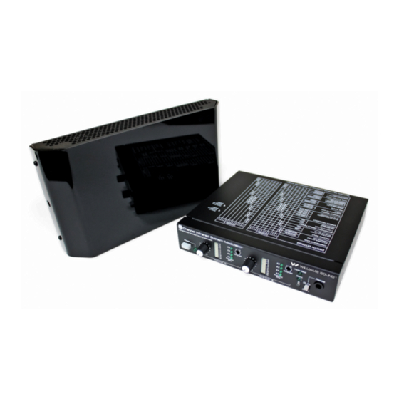
Modulator Model MOD 232
Emitter Model WIR TX9
Optional Receiver Models WIR RX22-4, WIR RX14-2, WIR RX16
MAN 132D
G
UIDE
ANUAL
Infrared Listening System
™
&
Advertisement
Table of Contents

Related Manuals for Williams Sound Sound Plus WIR TX925


Summary of Contents for Williams Sound Sound Plus WIR TX925
- Page 1 & NSTALLATION UIDE ANUAL Sound Plus Infrared Listening System ™ Model WIR TX925, Two-Channel Listening System Model WIR TX900, Four-Channel Listening System Model WIR SYS 1, Two-Channel Listening System Model WIR SYS 2, Two-Channel Listening System Model WIR SYS 2P, Two-Channel Listening System Model WIR SYS 4, Four-Channel Listening System RoHS Modulator Model MOD 232...
-
Page 2: Table Of Contents
™ OUND NFRARED ISTENING YSTEM NSTALLATION UIDE AND ANUAL Contents Page ..............3 YSTEM VERVIEW NSTALLATION... -
Page 3: System Overview
YSTEM VERVIEW The Williams Sound SoundPlus Infrared Listening System consists of a MOD 232 Modulator(s) and ™ one or more TX9 Emitters which use invisible infrared (IR) light to broadcast speech or music to wireless infrared receivers. The system is designed to transmit high quality audio for hearing assistance and language translation applications. -
Page 4: Mod 232 Modulator Setup
MOD 232 M ODULATOR ETUP The modulator is usually located with the sound system amplifier or mixer for easy access to an audio ETERMINE OCATION input signal. For portable systems, the modulator can be placed near the emitter or in another convenient location. - Page 5 The MOD 232 can directly drive one or two emitters. TX9 emitters repeat the baseband signal, so any ASEBAND ABLE ONNECTION number of emitters can be used. The modulator outputs CANNOT be split with CATV splitters. Determine the length of RG-58 cable needed to reach from the TX9 Emitter to the Modulator unit. Install BNC connectors to each end of the cable.
-
Page 6: Features & Controls
UDIO ONNECTION With the modulator DIP switches set for microphone Figure 5: Audio Connection input, the 3-pin XLR jack accepts balanced ICROPHONE NPUT microphones. Power for condenser microphones can be selected by DIP switch. The minimum input level is 100uV and the maximum level is 90 mV. With the modulator DIP switches set for line-level XLR L input, the 3-pin XLR jack accepts balanced line-level... -
Page 7: Configuration Settings
Figure 8 illustrates how to configure your system using the DIP switches (Figure 7) on the back of the ONFIGURATION ETTINGS MOD 232 Modulator. This diagram is also printed on top of the MOD 232 Modulator unit for quick reference. Figure 7: Configuration Switches Adjust switch settings on rear of MOD 232 Modulator here:... -
Page 8: Tx9 Emitter Setup
TX9 E MITTER ETUP TX9 L OCATION AND LACEMENT To determine the best location for the TX9 Emitter, it helps to think of the IR emitter as an invisible floodlight. You’ll want to aim it so the listeners are “flooded” with the infrared light. Mount the emitter at least 2 ft (.61 m) above the audience. -
Page 9: Coverage Area
OVERAGE Figure 11: Maximum Range when using the RX22-4, RX14-2, or RX16 receiver RX14-2 RX16 RX22-4 These patterns are the direct radiation pattern. The infrared radiation does not drop to zero outside the illustrated patterns; it decreases. It still may be useable at a greater distance, depending on the receiver sensitivity and the reflective characteristics of the room. - Page 10 ULTIPLE MITTERS NSTALLED TO AXIMIZE OVERAGE Figure 12A Figure 12A and !2B: Overlapping Illumination Patterns to Cover Larger Listening Areas Figure 12B Figure 13: Connecting Multiple TX9 Emitters An unlimited number of WIR TX9 emitters can be daisy-chained together to maximize the coverage area.
-
Page 11: Features & Controls
TX9 F EATURES AND ONTROLS Figure 14: TX9 Emitter Rear View For use with mounting bracket. Is visible on bottom OUNTING THE TO A ALL OR EILING Figure 15: Mounting the TX9 to a wall, ceiling, or suspended ceiling with the BKT 024 using a Mounting Plate or a T-Bar Clip... -
Page 12: Receiver Safety Instructions
If you have a pacemaker or other medical device, make sure that you are using this product in accordance with safety guidelines established by your physician or the pacemaker manufacturer. ECYCLING NSTRUCTIONS Help Williams Sound protect the environment! Please take the time to dispose of your ATTERY AFETY AND ISPOSAL equipment properly. -
Page 13: Optional Receivers
PTIONAL ECEIVERS Channel Frequency 2.3 MHz Figure 16: F WIR RX22-4 HANNEL ECEIVER ODEL 2.8 MHz 3.3 MHz 3.8 MHz Figure 17: WIR RX14-2 H EADSET ECEIVER Figure 16: WIR RX16 U NDER CHIN ECEIVER WIR RX16 Front View... -
Page 14: Troubleshooting
If the signal sounds okay, you may need to re-position the emitter panels or add additional panels. NOTE: Make sure the powerline voltage does not fall below 94V, or system performance will be greatly reduced! Check for ground loops or noise on the input signal. Call your Authorized Williams Sound UZZING UMMING OISE... -
Page 15: Warranty
IMITED ARRANTY Williams Sound products are engineered, designed, and manufactured under carefully controlled conditions to provide you with many years of reliable service. Williams Sound warrants the SoundPlus Infrared Listening ™ System against defects in materials and workmanship for FIVE (5) years. During the first five years from the purchase date, we will promptly repair or replace the SoundPlus Infrared Listening System. -
Page 16: Specifications
™ OUND NFRARED ISTENING YSTEM PECIFICATIONS WIR TX900, WIR TX925, WIR SYS 1, WIR SYS 2, WIR SYS 2P, WIR SYS 4 ODELS Two-Channel Modulator, Model MOD 232 Size, Weight: 8.5” W x 8.2” D x 1.7” H (21.5 cm x 20.8 cm x 4.4 cm), 3.1lbs. (1.5 kg) Color: Black epoxy paint with white legends Rack Mount:... -
Page 17: Model Tx9 Emitter
Multi–Channel Infrared Emitter, Model TX9 Dimensions, Weight: 11.25” W x 6.25” H x 2.125” D (28.6 cm x 15.9 cm x 5.4 cm), 1.9lbs (0.9 kg) Color: Black with white legends, red acrylic lens Power Supply: Wall Transformer, 24VAC, 50-60Hz, 35VA, 3-pin MOLEX Connector North America: TFP 010, UL/CSA Europe:... - Page 20 © 2009, Williams Sound Corp. MAN 132D...
Need help?
Do you have a question about the Sound Plus WIR TX925 and is the answer not in the manual?
Questions and answers