Table of Contents
Advertisement
Advertisement
Table of Contents

Related Manuals for Vibra HJK Series


Summary of Contents for Vibra HJK Series
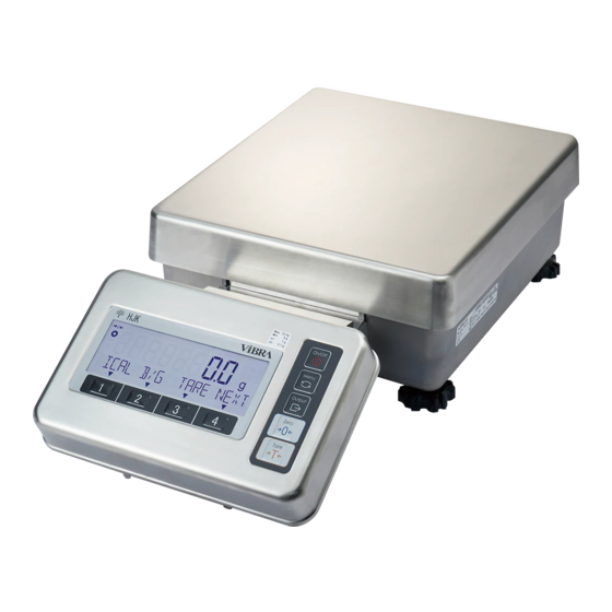
- Page 1 Precision Tuning-Fork Platform Scale HJK Series Manual Operation IMPORTANT To ensure safe and proper use of the scale, please read this manual carefully. After reading this manual, store it in a safe place near the scale, so you can review it as needed. SHINKO DENSHI CO., LTD.
- Page 2 Preface Thank you very much for having purchased Precision Tuning Fork Platform Scale HJK series. This document describes how to operate the product. Instructions ● The copyright of this document belongs to SHINKO DENSHI CO., LTD.. Reprinting or duplicating of all or part of this document without notice shall not be allowed.
-
Page 3: Important Notice
Important Notice ・It should be known that this product contains potential danger. And so please be sure to observe this document when installing, operating or servicing this product. ・SHINKO DENSHI CO., LTD. will not take any responsibility for any injury or damage caused by the non-observance of this document or misuse or unauthorized modification of this product. -
Page 4: How To Use This Document
How to use this document ■Symbols used in this document Understand the meaning of the following symbols and observe the instructions of this document. Symbols Meaning Used for high risk point concerning the operations that may lead to death or severe physical injury to persons if proper precautions are not taken. -
Page 5: Table Of Contents
Contents Preface ............................i Important Notice.......................... iii How to use this document ......................iv Contents ............................v 1 Prior to use ..........................1 1-1 Operating precautions ....................... 1 1-2 For more accurate measurement ..................3 1-2-1 Precautions related to measuring environment .............. 3 1-2-2 Precautions related to measuring table ................ - Page 6 3-7-1 Weighing by means of addition ..................36 3-8 Stabilization wait setting ....................37 3-9 Bar graph indication ......................37 3-10 Backlight setting ......................37 3-11 Auto power-off ....................... 38 3-12 Buzzer setting ....................... 38 3-13 “Simple SCS(Self Counting System) method” setting ........... 39 3-14 Range mode setting ......................
- Page 7 8-2 Shortcut setting for accessing various measuring modes ..........61 8-3 Free key setting ....................... 62 8-4 Adjustment and test ......................63 8-4-1 Span adjustment and span test ..................63 8-4-1(1) Span adjustment with external weight ................ 63 8-4-1(2) Span test with external weight ..................65 8-4-1(3) Semi-Automatic Span adjustment with internal weight ..........
-
Page 8: Prior To Use
1 Prior to use 1-1 Operating precautions ■Do not wet the AC adapter. That may cause an electric shock, short-circuiting or failure. ■Do not expose the AC adapter to dust. That may cause an electric shock, short-circuiting or failure. ■Do not handle the AC adapter with wet hands. That may cause an electric shock, short-circuiting or failure. - Page 9 ■Do not use the indicator unit in a wet/dusty location when AC adapter jack cover or D-sub 9p connector covers are opened. That may cause an electric shock, short-circuiting or failure. ■Do not connect to the AC adapter cord or communication cable with its connector or jack being wet.
-
Page 10: For More Accurate Measurement
1-2 For more accurate measurement To make more accurate measurement, it is necessary to lessen error-causing factors in measurement to the extent possible. Error-causing factors include not only an instrument error and performance of the scale itself but also the nature and condition of a specimen, measuring environment (vibration, temperature, humidity, etc.) and the like. -
Page 11: Precautions Related To A Specimen
1-2-3 Precautions related to a specimen Static → In general, synthetic resin- and glass-made specimens are high in electric insulation, electricity and so easily charged electrically. Weighing an electrically charged specimen makes the indication value unstable, reducing the reproducibility of the test result. Therefore, neutralize an electrically charged specimen before measurement. -
Page 12: Check For The Articles Contained In The Box
1-3 Check for the articles contained in the box The package box contains the following; If anything missing or broken should be found, please inform the store where you purchased the product. ①Weighing unit and indicator set: 1 ②Cable cover: 1 ③Base cover: 1 ④Indicator mounting bracket: 1 ⑤AC adapter: 1... -
Page 13: Name Of Each Section
1-4 Name of each section Indicator unit Weighing unit Weighing Pan Level AC adapter jack Adjusters (Adjustable legs) * Mount the connector cover when not connected. RS-232C connector (D-sub 9 pin male) Scale cable (Unremovable) * Mount the connector cover when not connected. Cover of hanging hook Connector for peripheral devices (The hook for hanging is an option. -
Page 14: Assembling And Installation Of The Product
1-5 Assembling and installation of the product 1-5-1(1) Procedure for installing the separate type scale without integrating the indicator unit Remove the weighing pan of the weighing unit. Slightly open both sides of the cable cover and mount it vertically in the cable housing. -
Page 15: 2) Procedure For Installing The Separate Type Scale With Integrating The Indicator Unit
1-5-1(2) Procedure for installing the separate type scale with integrating the indicator unit Remove the weighing pan of the weighing unit. Loosen the two knobs in the indicator mounting bracket and mount it vertically in the cable housing. Check that the supporting boards are hooked on the bottom of the cable housing. - Page 16 Put back the weighing pan. Then insert the indicator unit in the indicator mounting bracket at an angle. Mount the base cover vertically.
-
Page 17: Procedure For Connection With Ac Adapter And Peripherals
1-5-2 Procedure for connection with AC adapter and peripherals Be sure the AC adapter jack and Dsub-9p connectors not being wet. When not connected, be sure not leave covers of the AC adapter jack and Dsub-9P connectors open. Remove the covers for D-sub 9P connectors and connect RS232C cables when necessary Put the AC adapter plug to the AC adapter, remove the cap of AC adapter jack. -
Page 18: Level
1-5-3 Level At the time of shipment, the adjusters provided Release the transportation lock of the adjuster. at the four corners of the bottom are locked. Turn them in the direction shown in the figure on the left to loosen them. (1) While watching the level, turn the adjusters Level the scale. -
Page 19: How To Carry The Scale
1-6 How to carry the scale Make sure not to carry the scale with the cable hanging. Make sure not to carry the scale with weighing object on the weighing pan. Wearing the safety shoes and work gloves is highly recommended. Be careful not to apply excessive force to or impact the scale. -
Page 20: Description Of The Operation Keys
1-7 Description of the operation keys 1-7-1 Basic These keys are collectively called “functional keys” in this manual as a matter of convenience. Name of key Performance Turns on and off the power for the scale. [On/Off] On: Press the key, Off: Press the key long Used for calling/exiting the setting menu. -
Page 21: Setting Value And Numeric Value Inputting
1-7-2 Setting value and numeric value inputting Name of key Performance [Menu] Cancel the input value and go back to the setting menu. [Zero] Use for changing polarity <+/->. [Tare] Input a decimal point < . > in the “Multiplied by Coefficient mode” <... -
Page 22: How To Interpret The Display
1-8 How to interpret the display 1-8-1 Description of segment Mark Name Description Minus Indicates the negative weight value and numeric. When displayed: The scale is in the stable condition. When not displayed: The scale is not in the stable Stable mark condition. -
Page 23: Lcd Character Font
1-8-2 LCD character font ■7-segment comma point space minus / hyphen ■16-segment asterisk slash left arrow right arrow space plus minus / hyphen comma point percent Degree Celsius... -
Page 24: Basic Usage
2 Basic usage 2-1 Turning on/off the power, and checking for the operation After the scale has been moved, allow it to adapt to the ambient temperature for stable measurement. In addition, allow five minutes after turning on the power for the scale to warm up. Turn on the power for the scale. -
Page 25: Weighing Samples With Container (Tare)
2-3 Weighing samples with container (tare) When weighing samples placed on a container (tare), the weight of the container must be subtracted from the total weight to get the actual weight of the object to be weighed. This is called “tare subtraction” or “tare”. -
Page 26: Weighing The Additional Sample
2-4 Weighing the additional sample Weigh the first sample and the additional sample separately. Place a sample to be weighed. The mass of the sample to be weighed is indicated. Perform tare subtraction. Press [Tare] key. The indication changes to zero and the <... -
Page 27: Operation Of The Setting Menu
2-5-2 Operation of the setting menu To perform settings for various functions from the state of weighing, chiefly execute the following procedure. ■Go to the menu item to set ■Select the setting value and execute/fix. -
Page 28: Numeric Value Input
2-5-3 Numeric value input Input upper/lower limit, reference weight, unit weight, preset tare weight, coefficient, date/time and ID/password at each mode. Numeric value inputting is limited to eight digits at a maximum. Ex) When inputting “-5.4321”. Input “–”. - Press [Zero] key to change the polarity to “-”. Input “1”. -
Page 29: Functional Keys Switching At Each Measuring Mode
2-5-4 Functional keys switching at each measuring mode You can switch the measuring mode, or select and set the function, by operating the functional keys at each measuring mode. This chapter shows how the functions allocated to [1]-[3] keys switch by pressing [4] key. Refer to “3 Function related to the operation”... -
Page 30: Functions Related To The Operation
3 Functions related to the operation Settings to change the scale operations. 3-1 Hierarchy of functions related to the operation For verified scale: - Grey-shaded items ( ) are not indicated; - <17 WT STABLE> is not indicated and fixed to be <ON>. *1 <1D RANGE MODE>... - Page 31 Stability waiting 17 WT STABLE Valid ★ Bar graph indication 18 BARGRAPH Valid ★ Buzzer setting ★ 19 BUZZER MODE1 Mode 1 valid Back light setting 1A BACKLIGHT 3MIN 3 minutes 5MIN 5 minutes 10MIN 10 minutes 30MIN 30minutes Always ON ★...
-
Page 32: Various Measuring Modes Of The Scale
3-2 Various measuring modes of the scale Refer to “6 External input/output functions” to output the measuring data to other devices. 3-2-1 Weighing mode Weighing mode is the basic mode for weighing. Various functions can be used with weighing mode by using the “Free key”. Please refer to “8-3 Free key setting”. -
Page 33: 1) Actual Value Setting Method
3-2-2 (1) Actual value setting method Place the specified number of samples on the scale to record the average unit weight internally. Select whether or not employ the previous - Press [3]/[4] key to select whether or not recorded unit weight. employ the previous data. - Page 34 (1) When <on VAR> is selected in step 2, select the specified number of the sample among 1 to 999 by operating [1]/[2] keys. (2) When simple SCS is operating, if the weight of the samples is less than 99 times of the readability (d x 99), <Add>...
-
Page 35: 2) Numeric Value Setting Method
3-2-2 (2) Numeric value setting method Input numeric value of the unit weight by key operation. - Press [3]/[4] key to select whether or not Select whether or not employ the previous employ the previous data. recorded unit weight. When there is no data record, this step is skipped. -
Page 36: Percentage Mode
3-3 Percentage mode This mode is not legal for trade. The weight of a sample to be weighed is indicated in percent relative to the reference weight. There are two methods to input the reference weight; - Actual value setting method ([onW]) :Place the reference weight on the scale to record the weight. -
Page 37: Switching The Display At Percentage Mode
3-3-1 Switching the display at percentage mode Press [1]-[4] keys to switch the display. <ADD> and <TOTL> can be used when the <14 ADDITION> is activated. -
Page 38: Multiplied By Coefficient Mode
3-4 Multiplied by Coefficient mode Measured weight is multiplied by the pre-set coefficient, and the result be displayed. This mode is not available for verified scale. Select the Multiplied by Coefficient mode. - Press [Menu] key, then press [1]-[4] keys to go to <11 MODE>. - Press [4] key to change the setting value. -
Page 39: Switching The Display At Multiplied By Coefficient
3-4-1 Switching the display at Multiplied by Coefficient Press [1]-[4] keys to switch the display. <ADD> and <TOTL> can be used when the <14 ADDITION> is "Valid". 3-5 Unit setting Various units can be selected. Please also refer to "Appendix 3 Unit conversion table" and "Appendix 4 Weighing capacity and readability by unit"... -
Page 40: Comparator Function
3-6 Comparator function It is possible to preset threshold values (limits) and determine whether or not a measured value is within the range defined by the preset values. Refer to “5 Preset tare and Comparator setting” to preset the threshold values. The comparator function can be used in Weighing mode, Percentage mode, Counting mode, and Multiplied by Coefficient mode. -
Page 41: Comparator Function Setting
3-6-2 Comparator function setting When to use HI/OK/LO buzzer, be sure to set <19 BUZZER> to ON. (Refer to 3-12 Buzzer setting.) Lower limit, reference and upper limit can be also set by [1](LOW) key, [2](OK) key and [3](HIGH) key at “comparator indication” display. - Press [Menu] key, then press [1]-[4] keys to Select the comparator function. -
Page 42: Adding Function
- Press [1]-[2] keys to go to <137 LO BUZZER> Set LO buzzer - Press [4] key to change the setting value. - Press [1]/[2] key to select. OFF: ON : Active when below lower limit - Press [4] key to fix. Select relay output control This item is for optional relay output. -
Page 43: Weighing By Means Of Addition
3-7-1 Weighing by means of addition When <ADD> is assigned to [1] key and <TOTL> is assigned to [2] key. Place a first sample to be weighed. - Place a first sample to be weighed. - After < > appears, press [1](<<ADD>>) key. -
Page 44: Stabilization Wait Setting
3-8 Stabilization wait setting Set when to indicate the weighed value after the zero-point adjustment or tare; either after or before the weighed value stabilizes. For verified scale: - This setting menu is not available; - The scale always wait stabilization before indicating weighed value after the zero-point adjustment or tare. Select the stabilization wait setting. -
Page 45: Auto Power-Off
3-11 Auto power-off This function is to automatically turn off the power for the scale. Select the auto power-off. - Press [Menu] key, then press [1]-[4] keys to go to <1B AUTO OFF>. - Press [4] key to change the setting value. - Press [1]/[2] key to select. -
Page 46: Simple Scs(Self Counting System) Method" Setting
3-13 “Simple SCS(Self Counting System) method” setting “Simple SCS method” is auxiliary function for Counting mode. First, put a set number of samples in place. Next, put up to two times the set number of additional samples in place. The scale will automatically update the average sample weight. Repeating this step allows accurate counting. -
Page 47: Functions Related To The Performance
4 Functions related to the performance Set the scale indication stability and response speed. 4-1 Hierarchy of functions related to the performance For verified scale, grey-shaded items ( ) are not indicated. ★: Initial setting value Functions relating to Stability discrimination width ±0.5d the performance 21 STABLE... -
Page 48: Response Speed
4-3 Response speed The larger numeric value is set in this setting menu, the more stable the scale indication becomes in unstable conditions. Select the response speed. - Press [Menu] key, then press [1]-[4] keys to go to <22 RESPONSE>. - Press [4] key to change the setting value. -
Page 49: Preset Tare And Comparator Setting
5 Preset tare and Comparator setting Describes about setting items related to the preset tare weight and comparator function. 5-1 Hierarchy of Preset tare and Comparator setting For verified scale, grey-shaded items ( ) are not indicated. ★: Initial setting value Preset tare and Preset Tare Execution Invalid... -
Page 50: Preset Tare
5-2 Preset tare When using a tare whose weight is already known, the tare subtraction can be performed in advance by inputting its tare weight (preset tare weight). Five preset tare weight values can be registered. 5-2-1 Preset tare setting <31 PT MODE>... -
Page 51: 1) Actual Value Setting Method
5-2-2 (1) Actual value setting method Set a preset tare weight value. - Press [3] key to select. onW: Actual value - Place a sample to be weighed that is equivalent to the tare weight value. - Press [4] key to fix. - The preset tare weight value is stored. -
Page 52: Setting Of The Discrimination Value Of The Comparator Function
5-3 Setting of the discrimination value of the comparator function There are two ways of inputting a reference value and upper and lower limit values as described below: - Actual value setting method: Weighing a sample with a scale and then making it a setting value. - Numeric value setting method: Inputting a setting value directly via key operation. -
Page 53: Actual Value Setting Method
5-3-1 Actual value setting method Set a lower limit value. - Press [3] key to select. onW: Actual value - Place a sample to be weighed that is equivalent to the lower limit value. - Press [4] key to fix. The lower limit value is recorded. -
Page 54: External Input/Output Functions
6 External input/output functions This function is used for communication with the external peripheral devices. As standard equipment, there are RS-232C (D-SUB 9P) and Serial output for peripherals (D-SUB 9P). The RS-232C is bidirectional and the Serial output for peripherals is for output only. The RS-232C and the Serial output for peripherals output the same signal. -
Page 55: Connector Terminal Numbers, Their Functions And Specifications
6-2 Connector terminal numbers, their functions and specifications 6-2-1 D-SUB9P Connector for RS232C I/O Terminal No. Signal name Input/output Function - - - Input Receiving data Output Transmitting data HIGH Output (When the scale is powered ON) - Signal grounding -... -
Page 56: D-Sub9P Connector For Serial Output For Peripherals
6-2-2 D-SUB9P Connector for serial output for peripherals Terminal No. Signal name Input/output Function - - - - - - Output Transmitting data HIGH Output (When the scale is powered ON) - Signal grounding - - - - - - -... - Page 57 2. Meaning of the data Symbol Code Description [P1] (one character) Indicates the polarity of data. 0x2B Zero or positive data 0x2D Negative data [D1 to D9/D10] (nine or ten characters) Stores numeric data. 0-9 0x30-0x39 0 to 9 (numeric) 0 is also used for zero padding.
-
Page 58: Cbm Data Output Format
6-3-2 CBM data output format 1. Data composition ・ Measurement result: Composed of 26 characters including terminators (CR=0x0D, LF=0x0A) ␣ ␣ ・ Error message: Composed of 26 characters including terminators (CR=0x0D, LF=0x0A) ␣ ␣ ␣ ・Others (Date, Time etc.): The message “M1 M2 … Mn” is suffixed with terminators (CR=0x0D, LF=0x0A). …... -
Page 59: Input Command
6-4 Input command Commands input during the scale being busy (function setting, zero-point adjustment, tare subtraction etc.) are not accepted. Inputting command is available only through RS232C I/O. 6-4-1 Transmission procedure Send an input command from an external device to the scale. The table below shows the enable/disable of input commands in each measuring mode. -
Page 60: Input Command Composition 1
6-4-2 Input command composition 1 Composed of four characters including a terminator (CR=0x0D, LF=0x0A). 6-4-2 (1) Zero-point adjustment/Tare/Output control setting command Please take care not to take alphabetical “O” for Arabic number “0”. Response Code Code Description A00/Exx ACK/NAK (C1) (C2)... -
Page 61: 3) Span Adjustment/Test Command
6-4-2 (3) Span adjustment/test command The command “C4” is not accepted on verified scale. Response Code Code Description A00/Exx ACK/NAK (C1) (C2) format format Execute semi-automatic span adjustment with A00: ACK: 0x43 0x31 internal weight Normal Normal response response 0x43 0x32 Execute span test with internal weight E01:... -
Page 62: Response
6-5 Response 6-5-1 Response command format (A00/Exx format) Consists of five characters including terminators. 6-5-1(1) Response command code(A1) code(A2) code(A3) Description 0x41 0x30 0x30 Normal response 0x45 0x30 0x31 Abnormal response 6-5-2 Response command format (ACK/NAK format) Consists of one character without a terminator. 6-5-2(1) Response command code(A1) Description... - Page 63 Select the communication setting. Refer to the step 1 to key operation for setting. Select the communication condition. Set list 6 : 6-digit numeric format 7 : 7-digit numeric format 8 : 8-digit numeric format CSP6 : CSP 6-digit format CSP7 : CSP 7-digit format CBM : CBM format Select the output conditions.
-
Page 64: Functions Related To The Lock
7 Functions related to the lock Impose limitations on key operation and accessing the menu items, etc. 7-1 Hierarchy of functions related to the lock ★: Initial setting value Total lock release Execute (All locking disabled) Functions relating to the lock 51 ALL UNLOCK Cancel 5 LOCK... -
Page 65: Key Lock Function
7-3 Key lock function Key operation can be locked. Select the key lock function. - Press [Menu] key, then press [1]-[4] keys to go to <52 KEY LOCK>. - Press [4] key to change the setting value. - Press [1]/[2] key to select. OFF: No restriction 1: [On/Off] key invalid for power off Measuring indication:... -
Page 66: Controlling And Adjustment Functions
8 Controlling and adjustment functions Perform setting of the scale ID, the span adjustment/test and the date and time. 8-1 Hierarchy of controlling and adjustment functions *1 For non-verified scale, the initial setting value of <621 F1 KEY> is: - <CAL> for model without internal calibration weight; - <ICAL>... - Page 67 Span adjustment with Adjustment and test external weight Execute 63 MAINTENANCE 631 EX CAL Span test with external weight Execute 632 EX SPAN TEST Semi-automatic span adjustment with internal Execute weight 633 INT CAL Span test with internal weight Execute 634 INT SPAN TEST Calibrating the internal weight...
-
Page 68: Shortcut Setting For Accessing Various Measuring Modes
8-2 Shortcut setting for accessing various measuring modes Shortcuts for various measuring mode can be assigned to <<F1>>, <<F2>>, <<F3>> which are displayed above [1], [2], [3] key. For verified scale, only Weighing mode <WEIG>, Counting mode <COUN> and Percentage mode <PCNT> can be selected. Multiplied by Coefficient mode <MULT>... -
Page 69: Free Key Setting
8-3 Free key setting Free key setting is valid only in the weighing mode. <ICAL>, <GLPH> and <GLPF> are available only on the models with internal calibration weight. <READ> is not available on HJ62K0.1DS(R). <CAL> and <HOLD> are unavailable for verified scale. Various function can be assigned to the <<F1-F6>>... -
Page 70: Adjustment And Test
8-4 Adjustment and test 8-4-1 Span adjustment and span test Span adjustment is to “decrease” the difference between an indicated value and the true value (mass), and span test is to “check” the difference between an indicated value and the true value. This must be performed without fail in the case of doing high-accuracy weighing work. - Page 71 The span adjustment starts. For HJ17K0.1S(R) and HJ22K0.1S(R): - Place the weight in the centre of the weighing pan. ・For HJ17K0.1S(R) and J22K0.1S(R): Display changes to the order of <on FS> → “blinking of <on FS>”. Then span adjustment starts. For HJ33K0.1S(R), and HJ62K0.1DS(R): ・For HJ33K0.1S(R), HJ62K0.1DS(R): Display changes to the order of...
-
Page 72: 2) Span Test With External Weight
8-4-1(2) Span test with external weight Make sure to use the external weight which is equal to the weighing capacity of each model. Select the span test with external weight. - Press [Menu] key, then press [1]-[4] keys to go to <632 EX SPAN TEST>. - Press [4] key to execute. -
Page 73: 3) Semi-Automatic Span Adjustment With Internal Weight
8-4-1(3) Semi-Automatic Span adjustment with internal weight Do not power-off the scale while this function is operating. This function is available only on models with internal calibration device. Free key <<ICAL>> (span adjustment with internal weight) is assigned to <<F1>> on the models with internal calibration weight. -
Page 74: Calibrating The Internal Weight
8-4-2 Calibrating the internal weight Use this function to calibrate the internal weight by external weight. This function is unavailable for verified scale. (1) To calibrate more accurately, use a weight that is equivalent to the weighing capacity (Max). (2) An external weight used for the span adjustment shall be the one equivalent to: - OIML class F1 or higher for models with capacity of 33 kg and 62 kg;... - Page 75 For HJ33K0.1S(R), and HJ62K0.1DS(R): ・For HJ33K0.1S(R), and HJ62K0.1DS(R): Display changes to the order of <on FS> → <push M>. - Press [Menu] key. Display changes to “blinking of <on FS>”, then span adjustment starts. On completion of the span adjustment, the display automatically changes to <on 0>.
-
Page 76: Restore The Internal Weight Calibration Value To Default
8-4-3 Restore the internal weight calibration value to default This function is unavailable for verified scale. This function is available only on models with internal calibration device. Select the restore. - Press [Menu] key, then press [1]-[4] keys to go to <637 REF CAL RESTORE>. Execute the restore. -
Page 77: Scale Control Setting
8-5 Scale control setting 8-5-1 Scale ID setting A scale ID can be set to discriminate the scale. The scale ID is output with GLP header output and external span calibration/test result output. Scale ID is checked by free key <<ID>>. Select the scale ID setting. -
Page 78: 1) Administrator Password Registration
8-5-2 (1) Administrator password registration (1) Make sure not to forget the administrator password. (2) In case that the administrator password is lost, please contact the store where you purchased the product. Only one password can be set for administrator. Select the Administrator password registration. -
Page 79: Outputting Of The Span Adjustment / Test Result
8-5-3 Outputting of the span adjustment / test result After span adjustment/test, the result can be output automatically. Make sure to activate <41 RS232C> to output the data. Select the outputting. - Press [Menu] key, then press [1]-[4] keys to go to <645 SPAN OUT>. - Press [4] key to change the setting menu. -
Page 80: Time Setting
8-5-6 Time setting Select the time setting. - Press [Menu] key, then press [1]-[4] keys to go to <648 TIME SETTING>. - Press [4] key to change the setting menu. The digit for inputting is blinking. - Input the time. - Press [4] key to fix the time setting. -
Page 81: Readability Setting
8-5-8 Readability Setting The larger the readability becomes, the less the scale is affected by external influences. In addition, it takes less time for the scale reading to stabilize. Refer to “Appendix 1-1 Basic specifications” and “Appendix 4 Weighing capacity and readability by unit”... -
Page 82: Direct Start Setting
8-5-10 Direct start setting This is a function to turn on the scale automatically without pressing [On/Off] key when it is connected to the AC power. You can use this function when the scale is used in conjunction with other devices. Select the direct start. -
Page 83: Initialise
8-5-12 Initialise This function is to initialise the scale to the factory settings except span adjustment, the date and time setting. Select the initialise. - Press [Menu] key, then press [1]-[4] keys to go to <64E INITIALIZE>. - Press [4] key. - Press [3]/[4] key to select. -
Page 84: Troubleshooting
9 Troubleshooting If the trouble persists after following the procedures below, please contact the store you purchased. 9-1 Error message Error Message/ Cause Coping method Error Code OVER ERROR - The weight of the sample to be weighed is in - Split the sample into several pieces and excess of the maximum capacity. - Page 85 Error Message/ Cause Coping method Error Code ERR734 Weight of the sample is out of the importing Load the sample of which weight is within range at actual value setting method at the importing range. Percent weighing mode (lower limit to maximum capacity).
-
Page 86: How To Clean The Scale
10 How to clean the scale Take care not to wet the AC adapter. (1)Do not use items such as chemical agents or solvents for the switch panel or other resin components. (2)Do not dismount the pan base. (3)Take care not to apply excess force or impact to the scale. Turn the power off, disconnect the AC adapter and close the AC adapter jack with the rubber cap, disconnect RS232 cables and close the D-sub9p connector with cover. -
Page 87: Appendix
Appendix Appendix 1 Specifications Appendix 1-1 Basic Specifications For non Percentage Counting mode Span Mode minimum Model adjustment minimum reference unit weight weight HJ17K0.1S External 17000 g 0.1 g 0.1 g 10 g 17 kg 0.0001 kg 0.0001 kg 0.01 kg Internal 85000 ct 0.5 ct... - Page 88 Counting Percentage Span Mode mode Accuracy adjustm minimum minimum Model Class unit reference weight weight HJ17K0.1S External 17000 g 0.1 g 0.1 g 10 g 17 kg 0.005 kg 0.001 kg 0.0001 kg 0.0001 kg 0.01 kg Internal 85000 ct 25 ct 5 ct 5 ct...
-
Page 89: Appendix 1-2 Functional Specifications
Appendix 1-2 Functional specifications Item Description Weighing system Tuning-fork vibration method Measuring mode Weighing / Counting / Percentage / Multiplied by Coefficient Function - Function related to the operation Comparator / Adding / Stability waiting / Bar graph / Backlight / Auto power-off / Simple SCS / Range mode - Function related to the performance Stability discrimination width / Response speed / Zero tracking... - Page 90 Compatible printer CBM-910II Power Dedicated AC adapter (100-240 VAC / 50-60 Hz) Ratings AC adapter jack: 12 VDC, 2.4 VA (Maximum power consumption) Weight of the scale Approximately 18 kg (NET) Immunity: Industrial electromagnetic environment Emission: Class B Pan size 400 mm x 350 mm Operating condition Temperature:...
-
Page 91: Appendix 2 Dimensional Outline Drawing
Appendix 2 Dimensional outline drawing... -
Page 92: Appendix 3 Unit Conversion Table
Appendix 3 Unit conversion table Unit indication Conversion coefficient 1.00000000E+00 (gram) 1.00000000E-03 (kilogram) 5.00000000E+00 (carat) 2.2046226E-03 (pound) 3.5273961E-02 (ounce) 3.2150746E-02 (troy ounce) 1.5432358E+01 (grain) 6.4301493E-01 (pennyweight) 2.6666667E-01 (momme) 2.16999761E-01 (mesghal) 2.6717251E-02 (Hong Kong tael) 2.6455471E-02 (Singapore, Malaysia tael) 2.6666667E-02 (Taiwan tael) 8.5735324E-02 (tola) 6.59630607E-02... -
Page 93: Appendix 4 Weighing Capacity And Readability By Non-Metric Units
Appendix 4 Weighing capacity and readability by non-metric units These units are not available for verified scale. Model Unit HJ17K0.1S(R) HJ22K0.1S(R) HJ33K0.1S(R) HJ62K0.1DS(R) Gross 13.009 / 130 pound 0.0005 0.0005 0.0005 0.01 / 0.1 Gross 1100 210.09 / 2100 ounce 0.005 0.005 0.005... -
Page 94: Appendix 5 Scale Operation With Password Control Function
Appendix 5 Scale operation with password control function This chapter describes how to use the scale with “8-5-2 Password control”. This function is useful for setting different authority for each user/guest. Appendix 5-1 User’s authority setting Power on the scale. Enable the <642 PASSWORD>... -
Page 95: Appendix 5-2 User/Guest Login
Set the functions and setting values which are intended to be fixed. Refer to “3 Functions related to the operation”, “4 Functions related to the performance”, “5 Preset tare and Comparator setting”, “6 External input/output functions” and “8 Controlling and adjustment functions”... -
Page 96: Appendix 6 Operation With Internal Rechargeable Battery
Appendix 6 Operation with internal rechargeable battery This function can only be used with a scale equipped with optional internal rechargeable battery (factory option). Be sure to use the AC adapter supplied with the scale. A different AC adapter may cause the batteries to generate heat or explode.
Need help?
Do you have a question about the HJK Series and is the answer not in the manual?
Questions and answers