Table of Contents
Advertisement
Installation & Service Instructions
About the Boiler
About Safety
See inside cover for models covered by these instructions.
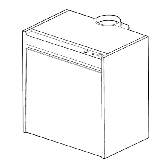
This Floor Standing Cast Iron Gas Boiler is available as Conventional Flue.
This boiler is for use with Natural Gas (G20) at 20mbar or Propane Gas (G31) at 37mbar and
for use in GB & IE.
The Gas Safety (Installation and Use) Regulations 1994 (As Amended) & The Gas
Safety(Installation and Use) (Amendment) Regulations 1996.
'' In your own interest, and that of safety, it is law that all gas appliances are installed by
competent persons, in accordance with the above regulations. Failure to install appliances
correctly could lead to prosecution.''
Installation must be in accordance with the Installation & Service Instructions and the rules in
force.
Leave these instructions with the user for use on future calls.
Osprey CF
125 – 220
Advertisement
Table of Contents

Subscribe to Our Youtube Channel
Related Manuals for Potterton Osprey CF 125


Summary of Contents for Potterton Osprey CF 125
- Page 1 Installation & Service Instructions Osprey CF 125 – 220 About the Boiler See inside cover for models covered by these instructions. This Floor Standing Cast Iron Gas Boiler is available as Conventional Flue. This boiler is for use with Natural Gas (G20) at 20mbar or Propane Gas (G31) at 37mbar and for use in GB &...
-
Page 2: Table Of Contents
Contents - Page 2 Technical Data ..............3 The models covered by these instructions are:- Introduction..............5 Osprey 125 - G.C. No. 41 589 33 Health & Safety Information ........5 Osprey 150 - G.C. No. 41 589 44 Codes of Practice............5 Osprey 180 - G.C. -
Page 3: Technical Data
Technical Data - Page 3 Heat Input & Efficiency figures are Boiler models quoted as gross Maximum Rate Output 35.0 43.0 52.8 64.5 Btu/h 119,420 146,716 180,154 220,074 Input 43.09 53.12 64.79 79.77 Btu/h 147,020 181,245 221,063 272,171 Gas rate (G20) m3/h 4.10 5.06... - Page 4 TECHNICAL DATA - Page 4 Fig. 2...
-
Page 5: Introduction
Installation & Service Instructions or otherwise recommended in writing. Any direct connection of a control device not approved by Potterton Myson Ltd, could invalidate the CE Certification and normal appliance warranty. -
Page 6: Installation Requirements
Part 19 - Building and Kitchen Work. If in doubt 2. and BS 5449: 1990 - Appendix B. advice must be sought from Potterton Myson. The complete installation must be tested for gas soundness Conventional flue boilers can be installed either in a kitchen and purged as described in BS6891. -
Page 7: Air Supply
Installation Requirements - Page 7 Conventional Flue Models 1.4 Air Supply The air requirements must meet BS 5440 Part 2 & BS 6644. The room in which the boiler is installed must be ventilated. Ventilation of the room containing the boiler shall include air for combustion and correct operation of the flue (ie Draft Diverter dilution). -
Page 8: Flue System
Installation Requirements - Page 8 1.5 Flue Systems A flue system (lined throughout its length) must be provided to evacuate the flue products of combustion from the boiler. Reference should be made to the building regulations and BS 5440:1. and the flue system efficiency should be checked in accordance with BS 5440 and BS 6644. -
Page 9: The System
Installation Requirements - Page 9 1.6 The System Sealed Systems (Fully Pumped) When installing the boiler on an existing system, the system Installation should be chemically cleaned prior to installation. The installation must comply with the requirements of The boiler must be used on INDIRECT hot water systems BS 6798: 1987 and BS 5449: 1990. - Page 10 Installation Requirements - Page 10 To size the expansion vessel it is first necessary to calculate Cylinder the volume of water in the system in litres. The following The hot water cylinder must be an indirect coil type or a volumes may be used as a conservative guide to calculating direct cylinder fitted with an immersion calorifier suitable for the system volume.
- Page 11 Installation Requirements - Page 11 Fig. 5 Fig. 6...
- Page 12 Installation Requirements - Page 12 Fig. 7 Fig. 8...
-
Page 13: Installation
2. Installation - Page 13 2.1 Prepare the boiler These instructions assume you have decided on where the boiler will be located. Carefully unpack the boiler. Do not discard any packaging until all the items are accounted for. Position the boiler to ensure the draft diverter is the required distance from the wall. -
Page 14: Connect The Gas Supply
Installation - Page 14 2.2 Connect the Gas Supply Ensure that the gas supply is isolated. Connect the gas supply to the gas cock using a 22mm copper pipe, sliding it in from the back panel to the gas cock. The pipe diameter required will depend on the boiler model and the pipe length from the gas meter. -
Page 15: Connect The Power Supply Cable
Installation - Page 15 2.4 Connect the Power Supply Cable The mains supply should be 230V 50Hz and fused at The mains wiring to the boiler has to be connected inside the control panel Access to the Control Panel Wiring Block Open the top panel of the boiler by unscrewing the rear screws. -
Page 16: Install The Room Thermostat
Installation - Page 16 2.5 Install the Room Thermostat If a Room Thermostat is to be fitted, the connections should be made in the wiring external to the boiler. 2.6 Install the flue Install the natural draft flue according to BS 5440 and Fig. -
Page 17: Commissioning
The commissioning and boiler adjustment must only be When purging and testing the gas supply for gas carried out by a suitably qualified personnel. Potterton soundness open all windows and doors in the room. Myson Ltd. offer this service on a chargeable basis. -
Page 18: Commission The Boiler
Commissioning - Page 18 3.1 Commission the Boiler 11 i. Press control knob in lightly and turn. Align position with marker Open Vented Systems - Remove the pump Press control knob in lightly and turn. Align and flush the system thoroughly with cold ignition position with marker water. -
Page 19: Final Adjustments
Section 4.6 - Servicing & Replacement of adequate servicing is carried out at least once Parts. a year by a Potterton Service Engineer or a C.O.R.G.I. Registered Installer. Overheat Thermostat The overheat thermostat is pre-set and no Leave a permanent card attached to the boiler adjustment is possible. -
Page 20: Service & Replacement Of Parts
4. Service & Replacement of Parts - Page 20 Read these: To ensure continued efficient operation of the appliance, it is recommended that it is checked and cleaned as necessary at regular intervals. The frequency of servicing will depend upon the particular installation conditions and usage but in general once per year should be adequate. -
Page 21: General Access
Service & Replacement of Parts - Page 21 4.1 General Access Warning: Before attempting to remove any component from the appliance first disconnect the mains electricity supply by removing the plug from the wall socket or by switching off the appliance at the external isolating switch and isolate the gas supply. -
Page 22: Ttb Thermostat
Re-assemble in reverse order. Note: This device is a safety feature and as such it should not be disabled or interfered with. Only Potterton parts should be used for replacement. If the unit continues to trip then the flue should be checked for spillage. Always check the operation of the TTB after every service. -
Page 23: Gas Valve
Service & Replacement of Parts - Page 23 4.7 Gas Valve • Gain General Access - See 4.1 Remove burner assembly - See 4.6 Disconnect gas valve lead. Unscrew pilot tube and thermocouple. Remove inlet and outlet plates. Re-assemble in reverse order. Check burner pressure and gas rate against the data badge using the pressure test point and gas meter, shown in Fig. -
Page 24: Wiring Diagrams
5. Wiring Diagrams - Page 24 Fig. 17... - Page 25 Wiring Diagrams - Page 25 Fig. 18...
-
Page 26: Fault Finding
6. Fault Finding - Page 26... - Page 27 Fault Finding - Page 27...
- Page 28 Fault Finding - Page 28 Fig. 19...
-
Page 29: Short List Of Spares
7. Short List Of Spare Parts - Page 29... - Page 30 7. Short List Of Spare Parts - Page 30 Item No. Catalogue No. Description Quantity G. C. No. 8000856 Gas Valve - SIT E03-650 8000854 Burner Bar - Polidoro E03-614 8000860 Injector E03-653 8000859 Injector Washer E03-652 8000909 Thermostat E03-683 8000871 Limit Thermostat E03-718...
Need help?
Do you have a question about the Osprey CF 125 and is the answer not in the manual?
Questions and answers