
Related Manuals for Potterton Osprey 2 CFL 125


Summary of Contents for Potterton Osprey 2 CFL 125
- Page 1 Osprey 2 CFL 125 - 150 - 180 - 220 Gas Fired Floor Standing Boiler Installation and Servicing Instructions Please leave these instructions with the user...
- Page 2 Natural Gas Potterton Osprey 2 CFL 125 G.C.N 41 590 54 Potterton Osprey 2 CFL 150 G.C.N 41 590 55 Potterton Osprey 2 CFL 180 The boiler meets the requirements of Statutory G.C.N 41 590 56 Instrument “ The Boiler (Efficiency) Regulations 1993 N 3083”...
-
Page 3: Table Of Contents
Contents Section Page Introduction General Layout Technical Data Dimensions System Details Site Requirements Installation Commissioning the Boiler Servicing the Boiler 10.0 Changing Components 11.0 Illustrated Wiring Diagram 12.0 Fault Finding 13.0 Short Parts List... -
Page 4: Introduction
Description 1. The Potterton Osprey 2 CFL is a fully automatic gas fired floor standing conventionally flued boiler with a cast iron heat exchanger. 2. The boiler is designed for use with fully pumped open vented or sealed water systems with an indirect hot water cylinder. -
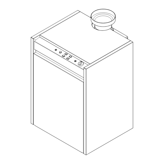
Page 5: General Layout
2.0 General Layout Layout Flue Spigot Draught Diverter Cable Clamp Flue Safety Thermostat Flow Connection Return Connection Burner Gas Inlet Connection Burner Ignition Control 10. Boiler Drain and Cap 11. Gas Valve 12. Burner Manifold 13. Pilot Feed Pipe 14. Pressure Test Point 15. -
Page 6: Technical Data
External Controls 230V switching Electrical Protection IP20 (Appliance must be connected to an earthed supply) SEDBUK Declaration For Potterton Osprey 2 CFL The seasonal efficiency (SEDBUK) 125: 78.6 % 150: 78.0 % 180: 78.3 % Flow Rate (l/min) 220: 78.0 % This value is used in the UK Government’s... -
Page 7: Dimensions
4.0 Dimensions Front Side Fig. 4 Fig. 5 Dimensions (mm) Model 332.5 427.5... -
Page 8: System Details
• It is important to check the inhibitor concentration after installation, system modification and at every service in accordance with the manufacturer’s instructions. (Test kits are available from inhibitor stockists.) • For information or advice regarding any of the above contact the Potterton Helpline. - Page 9 5.0 System Details Bypass 1. The boiler is fitted with a pump overrun device which allows the removal of residual heat from the boiler. The system design must therefore always provide an open circuit to allow water circulation between the boiler flow and return. 2.
-
Page 10: Site Requirements
Fig. 6 WARNING - The addition of anything that may interfere with the normal operation of the appliance without the express written permission of Potterton could invalidate the appliance warranty and infringe the Gas Safety (Installation and Use) Regulations. 700mm Clearances (Fig. - Page 11 6.0 Site Requirements Location 1. The boiler must be positioned on a flat and level floor or base which must be capable of supporting the full operational weight of the boiler. The flue must pass through an outside roof or wall and discharge to atmosphere in a position permitting satisfactory removal of combustion products.
- Page 12 6.0 Site Requirements Flues & Ventilation 1. The room or space of installation must be ventilated to ensure the correct and safe operation of the boiler. 2. 125 and 150 models require one air vent, at high or low level. High and low level vents are required for 180 and 220 models.
-
Page 13: Installation
Securing Screws 7.0 Installation Top Panel Initial Preparation The gas supply, gas type and pressure must be checked for suitability before connection. 1. Ensure that the floor or base on to which the boiler is to be fitted is clean and free from debris. 2. - Page 14 Securing Screws 7.0 Installation Top Panel Making the Electrical Connection 1. Undo the two securing screws from the rear of the top panel. Remove the panel (Fig. 13). 2. Swivel the two retaining plates through 90°. Lift the control box slightly and allow it to hinge forwards (Figs.
-
Page 15: Commissioning The Boiler
Commissioning the Boiler Thermostat Knob Commissioning the Boiler 1. Reference should be made to BS 5449 Section 5 when commissioning the boiler. 2. Open the water supply to the boiler. 3. The system must be flushed in accordance Fig. 18 with BS 7593, Section 5.1 of these instructions and the flushing agent manufacturers instructions. - Page 16 Commissioning the Boiler Securing Completion Screws Top Panel 1. Flush the system again and treat it in accordance with BS7593, Section 5.1 of these instructions and the flushing agent and inhibitor manufacturer’s instructions. 2. Carefully read and complete all sections of the “Benchmark”...
-
Page 17: Servicing The Boiler
Servicing the Boiler Securing Screws Top Panel Annual Servicing 1. For reasons of safety and economy, it is recommended that the boiler is serviced annually. Servicing must be performed by a competent person. 2. After servicing, complete the relevant section of the “Benchmark”... - Page 18 Servicing the Boiler Annual Servicing (Cont) 9. Undo the two nuts securing the valve, injector manifold and burner assembly to the boiler (Figs. 25 & 27). 10. Hold the manifold and carefully draw the assembly away from the boiler. Retain the Pilot Assembly washer from the gas inlet connection.
-
Page 19: Changing Components
10.0 Changing Components Securing Screws Top Panel IMPORTANT: When changing components ensure that both the gas and electrical supplies to the boiler are isolated before any work is started. Undo the two securing screws from the rear of the top panel. Remove the panel (Fig. 30). Disengage the retaining magnets at the top of the front panel and hinge forwards. - Page 20 10.0 Changing Components 10.2 Boiler Safety Thermostat Fig. 35 1. Swivel the two retaining plates through 90°. Lift the control box slightly and allow it to hinge forwards. Undo the two retaining screws and remove the cover panel (Figs. 35 & 37). Spring Clip Thermostat Phials...
- Page 21 10.0 Changing Components 10.4 Burner(s) 1. Undo the disconnecting union on the gas inlet. Remove the screw securing the burner ignition control to the gas valve. Draw the control off the valve (Fig. 43). 2. Undo the two nuts securing the valve, injector manifold and burner assembly to the boiler.
- Page 22 10.0 Changing Components 10.7 Flue Safety Thermostat 1. Undo the nut securing the Flue Safety Thermostat to the draught diverter. Ease the cable clamp from the slot in the draught diverter (Figs. 47 & 48). 2. Undo the screw retaining the earth wire to the boiler and disconnect the plug on the Flue Safety Thermostat cable from the boiler harness (Fig.
-
Page 23: Illustrated Wiring Diagram
11.0 Illustrated Wiring Diagram b 50 w 27 Flame Failure Neon (Red) Power ON Neon Flame Failure (orange) Reset Button Burner ON Neon (green) w 61 b 50 Safety Thermostat b 50 ON / OFF Button Safety Thermostat Neon (red) b 30 Control Thermostat w 42... -
Page 24: Fault Finding
12.0 Fault Finding Boiler Harness Burner Ignition Controller Socket 12.1 Fault Finding The following table indicates which wires from the main harness are connected to the socket. 1. This page shows the configuration of the plug and socket on the Burner Ignition Control supply Position Wire Identification (Fig. - Page 25 12.0 Fault Finding Is the “Power On” neon Is there 230V at SWL & N Does the On/Off button START illuminated ? on terminal strip? illuminate when pressed in? Is there permanent live Electrical fault external to Is there 230V at L & N of to the boiler? boiler the On/Off button?
- Page 26 12.0 Fault Finding Is there a spark at the Does the pump run ? electrode? Is there 230V at PL & PN Is the Boiler Safety on the terminal strip? Overheat neon illuminated? Check pump or pump Unscrew the cover and wiring press the reset button Check boiler internal...
- Page 27 12.0 Fault Finding BOILER Does the boiler shut down Does the pilot burner OPERATING when the flow Do the main burners light ? flame light ? CORRECTLY temperature reaches 85°? Ensure control knob is fully Does the spark continue Is there 20mb pressure at clockwise and the for 25 seconds? Gas Valve inlet?
-
Page 28: Short Parts List
V17000601 Flue Products Safety Thermostat V500540 Pilot Injector V17003216 Potterton, Baxi UK Limited, Brownedge Road, Bamber Bridge, Preston, Lancashire. PR5 6SN After Sales Service 08706 096 096 Technical Enquiries 08706 049 049 www.baxi.com PO890A0 Comp. No. 5106752 - Iss. 1 - 01/02...
Need help?
Do you have a question about the Osprey 2 CFL 125 and is the answer not in the manual?
Questions and answers