Table of Contents
Advertisement
Quick Links
SY-6ZB
Motherboard
****************************************************
®
Pentium
Processor supported
82440 ZX AGP/PCI Motherboard
66&100MHz Front Side Bus supported
Baby-AT Form Factor
****************************************************
User's Guide
Technical Reference
III, Pentium
&
®
II & Celeron™
Advertisement
Table of Contents

Subscribe to Our Youtube Channel
Related Manuals for SOYO SY-6ZB


Summary of Contents for SOYO SY-6ZB
-
Page 1: Technical Reference
SY-6ZB Motherboard **************************************************** ® ® Pentium III, Pentium II & Celeron™ Processor supported 82440 ZX AGP/PCI Motherboard 66&100MHz Front Side Bus supported Baby-AT Form Factor **************************************************** User's Guide & Technical Reference... -
Page 2: About This Guide
It is the policy of Soyo Computer Inc. to respect the valid patent rights of third parties and not to infringe upon or assist others to infringe upon such rights. -
Page 3: Table Of Contents
Table of Contents SY-6ZB Table of Contents SY-6ZB MOTHERBOARD LAYOUT..........1 CHAPTER 1 INTRODUCTION .............2 KEY FEATURES............2 HANDLING THE MOTHERBOARD......5 ELECTROSTATIC DISCHARGE PRECAUTIONS ..5 CHAPTER 2 HARDWARE SETUP ..........6 PREPARATIONS .............6 UNPACKING THE MOTHERBOARD .......7 INSTALLATION GUIDE..........8 CHAPTER 3 BIOS SETUP UTILITY ...........29 SOYO COMBO SETUP .........31... -
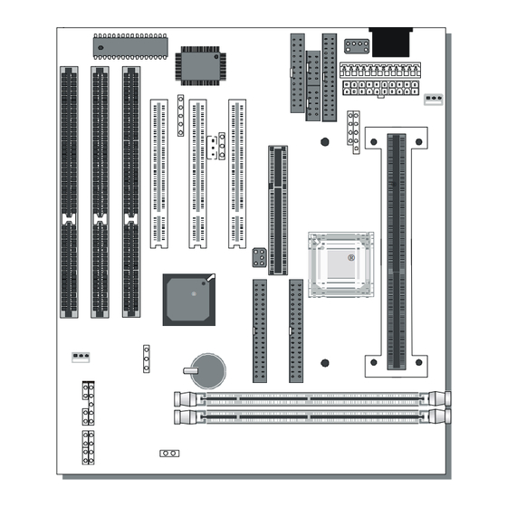
Page 4: Sy-6Zb Motherboard Layout
Motherboard Features SY-6ZB SY-6ZB MOTHERBOARD LAYOUT PS/2 Mouse Connector Connector Flash BIOS ITE8671 AT Power ATX Power PRT 1 CPUFAN JP50 COM 1 COM 2 AGP Slot JP44 Slot 1 ® Header PCI Slot #3 PCI Slot #2 PCI Slot #1 Intel ®... -
Page 5: Chapter 1 Introduction
Introduction SY-6ZB Chapter 1 INTRODUCTION The SY-6ZB AGP/PCI Motherboard is a high-performance Slot 1 processor supported Baby-AT form-factor system board. SY-6ZB uses the 82440 ZX Chipset technology and supports Slot 1 processors. This Motherboard is fully compatible with industry standards and adds many technical enhancements. - Page 6 Introduction SY-6ZB SY-6ZB PLATFORM FEATURES Board Size 4-layer PCB, 22x25cm(8.7”x 9.8”), Baby-AT Form Factor ® ® Slot1 Slot 1 for Pentium III, Pentium II & Celeron™ Processor Ø Supports the following processors 100MHz FSB ® Pentium II 350/400/450 MHz ®...
- Page 7 Introduction SY-6ZB Ø IDE1: Primary IDE Device Connector Ø IDE2: Secondary IDE Device Connector Ø Supports Ultra DMA/33 1 Floppy Disk Drive (FDD) Port (Supports 1.2MB/1.44MB/2.88MB and LS120/3-mode FDD) 5-pin Serial Infrared Device Header Keylock 5-pin KeyLock Header Reset 2-pin Reset Switch Header...
-
Page 8: Handling The Motherboard
Introduction SY-6ZB 1-2 HANDLING THE MOTHERBOARD To avoid damage to your Motherboard, follow these simple rules while unpacking: Ø Before handling the Motherboard, ground yourself by grasping an unpainted portion of the system's metal chassis. Ø Remove the Motherboard from its anti-static packaging. Hold the Motherboard by the edges and avoid touching its components. -
Page 9: Chapter 2 Hardware Setup
Hardware Setup SY-6ZB Chapter 2 HARDWARE SETUP Congratulations on your purchase of SY-6ZB Motherboard. You are about to install and connect your new Motherboard. Note: Do not unpack the Motherboard from its protective anti-static packaging until you have made the following preparations. -
Page 10: Unpacking The Motherboard
Hardware Setup SY-6ZB 2-2 UNPACKING THE MOTHERBOARD When unpacking the Motherboard, check for the following items: Ø The SY-6ZB 440 ZX AGP/PCI Motherboard Ø This Quick Start Guide * Ø The Installation CD-ROM * Ø One IDE Device Flat Cable Ø... -
Page 11: Installation Guide
Motherboard or system. BEGIN THE INSTALLATION Step 1. CPU Installation Your SY-6ZB motherboard comes with a CPU retention set kit. The retention set is used to hold the processor attached to the Slot 1 CPU connector on the motherboard. - Page 12 Hardware Setup SY-6ZB Open the two sides by folding them up. Push the locks on top of the CPU inward.
- Page 13 Hardware Setup SY-6ZB Insert the CPU into the retention module. The CPU fits in the CPU slot in only ONE way, do not try to force it in. After completely inserting the CPU, push the two locks on top of the CPU outward.
- Page 14 Hardware Setup SY-6ZB Note: Installing a heat sink and cooling fan on top of your CPU is necessary for proper heat dissipation. Failing to install these items may result in overheating and possible burn-out of your CPU. Step 2. CPU Fan Installation Your Slot 1 processor kit comes with a cooling fan.
- Page 15 Hardware Setup SY-6ZB Step 3. SDRAM Memory Module Installation This Motherboard features 2 x DIMM Banks for 168-pin 3.3V unbuffered two DIMM modules. Your board comes with two DIMM sockets, providing support for up to 256MB of main memory using DIMM modules from 8MB to 128MB.
- Page 16 Hardware Setup SY-6ZB Step 4. IDE Device Installation (HDD, CD-ROM) This Motherboard offers two primary and secondary IDE device connectors (IDE1, IDE2.) It can support up to four high-speed HDD or CD-ROM. Connect one side of the 40-pin flat cable to the IDE device (HDD or CD-ROM) and plug the other end to the primary (IDE1) or secondary (IDE2) directionally keyed IDE connector on the Motherboard.
- Page 17 Hardware Setup SY-6ZB Plug the computer case's front panel devices to the corresponding headers on the Motherboard. 1. Power LED & KeyLock Plug the Power LED cable into the 5-pin Keylock header. Some systems may feature a KeyLock function with a front panel switch for enabling or disabling the keyboard.
- Page 18 Hardware Setup SY-6ZB 6. ATX Power On/Off Switch Attach the 2-pin momentary type switch to the PWRBT header for turning On or Off your ATX power supply.
- Page 19 Hardware Setup SY-6ZB Step 7. External Peripherals Connections External devices such as the keyboard, printer, PS/2 mouse, modem, USB can be connected to the Motherboard. Normally, you can not plug your devices directly onto the Motherboard, except for the keyboard that plugs directly into the back panel KB connector.
- Page 20 Hardware Setup SY-6ZB 1. Serial Ports COM1/COM2 External peripherals that use serial transmission scheme include serial mouse and modem. Your motherboard comes with two types of serial connectors with flat cables: Ø one 9-pin male external connector with 9-pin flat cable Ø...
- Page 21 Hardware Setup SY-6ZB 2. Parallel Port PRT1 This parallel port is used to connect the printer or other parallel devices. Your motherboard comes with one 25-pin female external parallel connector with 25-pin flat cable. Plug the 25-pin end of the flat cable into the PRT1 parallel connector on the motherboard, as shown in the figure below, then fix the external 25-pin connector to the rear panel of the computer case.
- Page 22 Hardware Setup SY-6ZB 3. AT Keyboard Plug the keyboard jack directly into the 5-pin female AT keyboard connector located at the rear panel of the Motherboard. AT Keyboard Connector 4. PS/2 Mouse Attach the mouse cable to the 6-pin male PS/2 mouse connector on the motherboard to enable PS/2 mouse function.
- Page 23 Hardware Setup SY-6ZB Step 8. Other Connections 1. Wake-On-LAN (WOL) Attach the 3-pin connector from the LAN card which supports the Wake-On-LAN (WOL) function to the JP44 header on the Motherboard. This WOL function lets users wake up the connected computer through the LAN card.
- Page 24 Hardware Setup SY-6ZB Step 9. Cooling Fan Installation 1. CPU Cooling Fan After you have seated the CPU properly on the processor, attach the 3-pin fan cable to the CPUFAN connector on the Motherboard. The fan will stop when the system enters into Suspend Mode. (Suspend mode can be enabled from the BIOS Setup Utility, [POWER MANAGEMENT] menu.)
- Page 25 Hardware Setup SY-6ZB Step 10. AGP VGA Card Insert the AGP VGA card into the AGP slot. Then connect the monitor information cable to the AGP card back plane external connector. Follow the manufacturer's instructions to perform the AGP VGA drivers installation.
- Page 26 Hardware Setup SY-6ZB Warning: Follow these precautions to preserve your Motherboard from any remnant currents when connecting to ATX power supply: Turn off the power supply and unplug the power cord of the ATX power supply before connecting to ATX PW connector.
- Page 27 Hardware Setup SY-6ZB Step 14. CMOS Clearing (JP5) After you have turned off your computer, clear the CMOS memory by momentarily shorting pins 2-3 on jumper JP5, for a few seconds. Then restore JP5 to the initial 1-2 jumper setting in order to recover and retain the default settings.
-
Page 28: Bus Clock
Hardware Setup SY-6ZB Step 16. Set SW1 for power up FSB clock and AGP bus clock. SW1 is used to adjust AGP bus clock frequency depending on the value of the front side bus (FSB) clock, also the setting of the SW1 determines the power up FSB clock which will remain effective until the BIOS set the FSB clock to the CMOS setting. - Page 29 This Motherboard does not use any hardware jumpers to set the CPU frequency. Instead, CPU settings are software configurable with the BIOS [SOYO COMBO SETUP]. The [SOYO COMBO SETUP] menu combines the main parameters that you need to configure, all in one menu, for a quick setup in BIOS.
-
Page 30: Hardware Setup
: Load BIOS Defaults : Load Setup Defaults Available [CPU Frequency] settings on your SY-6ZB Motherboard are detailed in the following table. If you set this field to [Manual], you are then required to fill in the next two consecutive fields: (1) the CPU Host/PCI Clock, and (2) the CPU Ratio. -
Page 31: Troubleshooting At First Start
Hardware Setup SY-6ZB and continue the boot sequence. Troubleshooting at First Start What should I do if the Motherboard refuses to start? The 350MHz setting is used as default so whenever the BIOS settings are erased or reset, the board will be able to boot up. -
Page 32: Chapter 3 Bios Setup Utility
BIOS Setup Utility SY-6ZB Chapter 3 BIOS SETUP UTILITY This motherboard's BIOS setup program uses the ROM PCI/ISA BIOS program from Award Software Inc. To enter the Award BIOS program's Main Menu: 1. Turn on or reboot the system. 2. After the diagnostic checks, press the [Del] key to enter the Award BIOS Setup Utility. -
Page 33: Save And Exit Setup
BIOS Setup Utility SY-6ZB Hot Keys: Function keys give you access to a group of commands throughout the BIOS utility. Function Command Description Help Gives the list of options available for each item. Color Change the color of the display window. -
Page 34: Standard Cmos Setup
BIOS Setup Utility SY-6ZB 3-1 STANDARD CMOS SETUP Select the [STANDARD CMOS SETUP] option from the Main Menu and press [Enter] key. ROM PCI/ISA BIOS STANDARD CMOS SETUP AWARD SOFTWARE, INC. Date (mm:dd:yy) : Fri, Feb 1 1995 Time (hh:mm:ss) - Page 35 BIOS Setup Utility SY-6ZB 3-1.2 Hard Disks Type & Mode Choose the type and mode for the hard disks that you have already installed. Primary Setting Description Note (Secondary) Master & Slave Type Auto BIOS detects hard disk type Default automatically.
- Page 36 BIOS Setup Utility SY-6ZB 3-1.4 Video Select the video mode: EGA/VGA (Default), CGA 40×25, CGA 80×25, Mono (Monochrome). 3-1.5 Halt On When the BIOS detects system errors, this function will stop the system. Select which type of error will cause the system halt: All Errors (Default), No Errors, All But Diskette, All But Keyboard, All But Disk/Key.
-
Page 37: Bios Features Setup
BIOS Setup Utility SY-6ZB 3-2 BIOS FEATURES SETUP Select the [BIOS FEATURES SETUP] option from the Main Menu and press [Enter] key. ROM PCI/ISA BIOS BIOS FEATURES SETUP AWARD SOFTWARE, INC. Virus Warning : Disabled Video BIOS Shadow : Enabled... - Page 38 BIOS Setup Utility SY-6ZB 3-2.1 Virus Warning Setting Description Note Virus Warning Disabled Default Enabled Enable this option to protect the boot sectors and partition tables of your hard disk. Any attempt to write to them will the system to halt and display a warning message.
- Page 39 BIOS Setup Utility SY-6ZB 3-2.3 System Boot Control Settings System Boot Setting Description Note Control Settings Quick Power On Disabled Self Test Enabled Provides a fast POTS at Default boot-up. Boot Sequence A, C, SCSI Choose the boot sequence adapted to...
- Page 40 BIOS Setup Utility SY-6ZB 3-2.4 Typematic Settings Typematic Setting Description Note Settings Typematic Disabled Default Rate Setting Enabled Enable to adjust the keystroke repeat rate. Typematic Rate Char / sec Choose the rate a character keeps repeating. Typematic Delay Msec...
- Page 41 BIOS Setup Utility SY-6ZB Other Control Options (continued) Other Control Setting Description Note Options Assign IRQ Disabled Default For VGA Enabled When using a video card that requies an IRQ. OS Select for When using an OS2 DRAM>64MB operating system.
-
Page 42: Chipset Features Setup
BIOS Setup Utility SY-6ZB 3-3 CHIPSET FEATURES SETUP Caution: Change these settings only if you are already familiar with the Chipset. The [CHIPSET FEATURES SETUP] option changes the values of the chipset registers. These registers control the system options in the computer. - Page 43 BIOS Setup Utility SY-6ZB CHIPSET FEATURES SETUP CHIPSET Setting Description Note FEATURES Auto Enabled It is strongly recommended Default Configuration to enable this option so that the system automatically sets all options on the left panel of the screen (except for cache update &...
- Page 44 BIOS Setup Utility SY-6ZB CHIPSET FEATURES SETUP (Continued) CHIPSET Setting Description Note FEATURES Passive Release Enabled Use the default setting Default Delayed Enabled Use the default setting Default Transaction AGP Aperture 4MB- AGP could use the DRAM Size 256MB as its video RAM. Choose...
- Page 45 BIOS Setup Utility SY-6ZB CHIPSET FEATURES SETUP (Continued) CHIPSET Setting Description Note FEATURES If [CPU Speed] is set to [Manual] CPU Host Clock Select the host clock of your 66 MHz ® Select Pentium II processor among these 68 MHz values.
- Page 46 BIOS Setup Utility SY-6ZB CHIPSET FEATURES SETUP (Continued) CHIPSET Setting Description Note FEATURES Current CPUFAN Show the current status of °C/°F Speed CPU Fan Current CHSFAN Show the current status of °C/°F Speed CHS Fan VID, VTT, 3.3V, Show the current voltage +12V, -5V, +5V, status.
-
Page 47: Power Management Setup
BIOS Setup Utility SY-6ZB 3-4 POWER MANAGEMENT SETUP The [POWER MANAGEMENT SETUP] sets the system's power saving functions. ROM PCI/ISA BIOS POWER MANAGEMENT SETUP AWARD SOFTWARE, INC. ACPI function : Disabled ** Reload Global Timer Events ** Power Management : User Define... - Page 48 BIOS Setup Utility SY-6ZB 3-4.1 Power Management Controls Power Setting Description Note Management Controls ACPI Disabled Default function Enabled ACPI (Advanced Configuration Power Management Interface) Power User Define Lets you define the HDD and Default Management system power down times.
- Page 49 BIOS Setup Utility SY-6ZB 3-4.2 PM Timers PM Timers Setting Description Note Doze Mode Disabled Default 1Min- When the set time has System clock 1Hour elapsed, BIOS sends a drops to command to the system to 33MHz. enter Doze Mode.
- Page 50 BIOS Setup Utility SY-6ZB PM Events (continued) PM Events Setting Description Note CPUFAN Off Disabled Disables the PM timer. In Suspend Enabled Switches off the CPU Fan Default when the system enters Suspend Mode. Resume by Disabled Default Ring Enabled The system will resume active when the modem is ringing.
-
Page 51: Pnp/Pci Configuration Setup
BIOS Setup Utility SY-6ZB 3-5 PNP/PCI CONFIGURATION SETUP This option sets the motherboard's PCI Slots. ROM PCI/ISA BIOS PNP/PCI CONFIGURATION AWARD SOFTWARE, INC. Used MEM base addr : N/A PnP OS Installed : No Resources Controlled By : Manual Assign IRQ For USB... - Page 52 BIOS Setup Utility SY-6ZB 3-5.1 PNP/PCI Configuration Controls PNP/PCI Setting Description Note Controls PnP OS Set this field to [Yes] if Installed you are running Windows 95, which is PnP compatible. If the OS you are Default (If there is any...
- Page 53 BIOS Setup Utility SY-6ZB 3-5.2 PNP/PCI Configuration Setup PNP/PCI Setting Description Note Setup If [Resources Controlled By] is set to [Manual] IRQ-3,4,5,7,9,10, IRQ-# and PCI/ISA PnP Choose IRQ-# and 11,12,14,15 DMA-# DMA-# assigned to DMA-0,1,3,5,6,7 assigned to: PCI/ISA PnP card.
- Page 54 BIOS Setup Utility SY-6ZB 3-6 LOAD SETUP DEFAULTS Select the [LOAD SETUP DEFAULTS] option from the Main Menu to load the system values you have previously saved. This option is recommended if you need to reset the system setup and to retrieve the old values.
-
Page 55: Integrated Peripherals
BIOS Setup Utility SY-6ZB 3-8 INTEGRATED PERIPHERALS Caution: Change these settings only if you are already familiar with the Chipset. The [INTEGRATED PERIPHERALS] option changes the values of the chipset registers. These registers control the system options in the computer. - Page 56 BIOS Setup Utility SY-6ZB 3-8.1 IDE Device Controls IDE Controls Setting Description Note IDE HDD Block Mode Disabled Enabled Invokes multi-sector Default transfer instead of one sector per transfer. Not all HDDs support this function. mode 0 is the slowest speed Ø...
- Page 57 BIOS Setup Utility SY-6ZB 3-8.2 Keyboard Controls Keyboard Setting Description Note Controls USB Keyboard Disabled Turn off the on-board Default Support Enabled Use a USB keyboard Init AGP Display Disabled Default First Enabled If you choose to initialize the AGP...
- Page 58 BIOS Setup Utility SY-6ZB 3-8.3 FDC Controls FDC Controls Setting Description Note Onboard FDC controller Disabled Turn off the on-board floppy controller Enabled Use the on-board Default floppy controller 3-8.4 Onboard Serial Ports Onboard Serial Setting Description Note Ports Onboard PORT 1...
- Page 59 BIOS Setup Utility SY-6ZB 3-8.5 Onboard Parallel Ports Onboard Parallel Setting Description Note Ports Onboard Parallel Disabled Choose the printer I/O Port address. 378/IRQ7 Default 3BC/IRQ7 278/IRQ5 Parallel Port Mode ECP+EPP The mode depends on Default your external device that connects to this port.
-
Page 60: Supervisor Password
BIOS Setup Utility SY-6ZB 3-9 SUPERVISOR PASSWORD Based on the setting you have made in the [Security Option] of the [BIOS FEATURES SETUP] section, the password prevents access to the system or the setup program by unauthorized users. Follow this procedure to set a new password or disable the password: Choose [BIOS FEATURES SETUP] in the Main Menu and press [Enter]. -
Page 61: User Password
BIOS Setup Utility SY-6ZB Enter your new password and press [Enter]. The following message appears, prompting to confirm the new password: Re-enter your password and then press [Enter] to exit to the Main Menu. This diagram outlines the password selection procedure: ↔... -
Page 62: Ide Hdd Auto Detection
BIOS Setup Utility SY-6ZB 3-11 IDE HDD AUTO DETECTION This Main Menu function automatically detects the hard disk type and configures the STANDARD CMOS SETUP accordingly. ROM PCI/ISA BIOS CMOS SETUP UTILITY AWARD SOFTWARE, INC. HARD DISKS TYPE SIZE CYLS... -
Page 63: Chapter 4 Drivers Installation
The SOYO CD Start Up Program automatically detects which SOYO Motherboard you own and displays the corresponding model name. Step 1. Insert the SOYO CD into the CD-ROM drive The SOYO CD will auto-run, and the SOYO CD Start Up Menu will display as shown below. - Page 64 Drivers installation SY-6ZB Step 2. Install Drivers Click the Install Drivers button to display the list of drivers software that can be installed with your Motherboard. The Start Up program displays the drivers available for the particular model of Motherboard you own. We recommend that you only install those drivers.
- Page 65 DMA (Direct Memory Access) to relieve the CPU of this burden, thus speeding up the system. The SOYO SpeedPro driver makes use of an advanced caching algorithm, which gives it an advantage over other busmaster drivers.
- Page 66 Note: Do NEVER install two types of busmaster drivers on your system, this will lead to conflicts and system instability. Therefore, if you install the SOYO SpeedPro Busmaster driver you can NOT install the Intel Busmaster drivers. Before installing a new busmaster driver first UNINSTALL the old busmaster driver.
- Page 67 Note: However, to display the list of all drivers software available with SOYO Motherboards, click the Display all drivers on the SOYO CD button. Please make sure to install only the drivers adapted to your system, or otherwise this cause system malfunctions.
- Page 68 SY-6ZB Notice 3: Once you have selected a driver, the system will automatically exit the SOYO CD to begin the driver installation program. When the installation is complete, most drivers require to restart your system before they can become active.
Need help?
Do you have a question about the SY-6ZB and is the answer not in the manual?
Questions and answers