Table of Contents
Advertisement
Advertisement
Table of Contents

Subscribe to Our Youtube Channel
Related Manuals for SOYO SY-6ZE+


Summary of Contents for SOYO SY-6ZE+
-
Page 1: Technical Reference
SY-6ZE+ Motherboard **************************************************** ® ® Pentium III, Pentium II & Celeron™ Processor supported 82440 ZX AGP/PCI Motherboard 66&100MHz Front Side Bus supported ATX Form Factor **************************************************** User's Guide & Technical Reference... -
Page 2: About This Guide
It is the policy of Soyo Computer Inc. to respect the valid patent rights of third parties and not to infringe upon or assist others to infringe upon such rights. -
Page 3: Table Of Contents
CHAPTER 2 HARDWARE SETUP ..........6 PREPARATIONS .............6 UNPACKING THE MOTHERBOARD .......7 INSTALLATION GUIDE..........8 CHAPTER 3 BIOS SETUP UTILITY ...........26 SOYO COMBO SETUP .........28 STANDARD CMOS SETUP ........33 BIOS FEATURES SETUP ........36 CHIPSET FEATURES SETUP .......41 POWER MANAGEMENT SETUP......44 PNP/PCI CONFIGURATION SETUP......48 LOAD SETUP DEFAULTS ........51... -
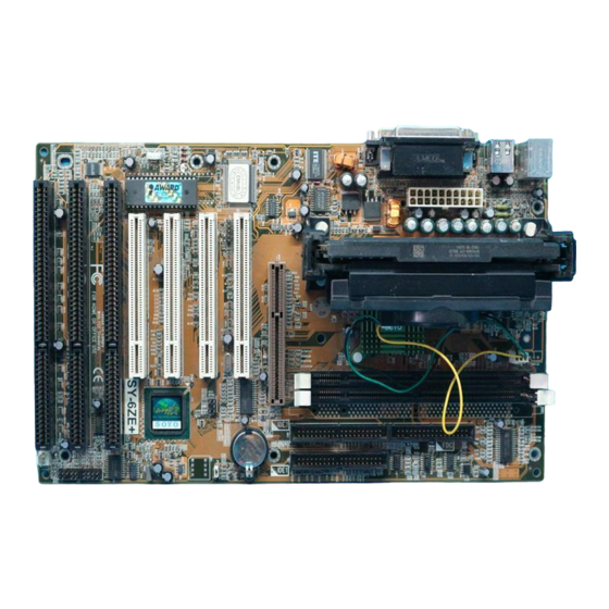
Page 4: Sy-6Ze+ Motherboard Layout
Motherboard Features SY-6ZE+ SY-6ZE+ MOTHERBOARD LAYOUT PS/2 KB PS/2 Mouse JP10 Connector Connector DIMM 1 DIMM 2 USB 1 USB 2 CPUFAN Slot 1 ® COM 1 ® COM 2 Intel 82443 ZX Power AGP Slot IDE 2 IDE 1 PCI Slot #1 I/O Chipset IT8671F-A... -
Page 5: Chapter 1 Introduction
Hardware Doctor ™ utility Supports Creative SB-LINK ™ (PC-PCI) for PCI audio 1 x 32-bit AGP slot 4 x 32-bit bus mastering PCI slots 2 x USB ports onboard 1 x IrDA port Supports multiple-boot function SOYO COMBO Setup... - Page 6 Introduction SY-6ZE+ SY-6ZE+ PLATFORM FEATURES Board Size 4-layer PCB, 18x30.5cm(7.1”x12”), ATX Form Factor ® ® Slot1 Slot 1 for Pentium III, Pentium II & Celeron™ Processor Ø Supports the following processors 100MHz FSB ® Pentium II 350/400/450 MHz ® Pentium III 450/500 MHz 66MHz FSB ®...
- Page 7 Introduction SY-6ZE+ Ø IDE1: Primary IDE Device Connector Ø IDE2: Secondary IDE Device Connector Ø Supports Ultra DMA/33MHz 1 Floppy Disk Drive (FDD) Port (Supports 1.2MB/1.44MB/2.88MB and LS120/3-mode FDD) 5-pin Serial Infrared Device Header Keylock 5-pin KeyLock Header Reset 2-pin Reset Switch Header Speaker 4-pin PC Speaker Header TB_LED...
-
Page 8: Handling The Motherboard
Introduction SY-6ZE+ 1-2 HANDLING THE MOTHERBOARD To avoid damage to your Motherboard, follow these simple rules while unpacking: Ø Before handling the Motherboard, ground yourself by grasping an unpainted portion of the system's metal chassis. Ø Remove the Motherboard from its anti-static packaging. Hold the Motherboard by the edges and avoid touching its components. -
Page 9: Chapter 2 Hardware Setup
Hardware Setup SY-6ZE+ Chapter 2 HARDWARE SETUP Congratulations on your purchase of SY-6ZE+ Motherboard. You are about to install and connect your new Motherboard. Note: Do not unpack the Motherboard from its protective anti-static packaging until you have made the following preparations. -
Page 10: Unpacking The Motherboard
Hardware Setup SY-6ZE+ 2-2 UNPACKING THE MOTHERBOARD When unpacking the Motherboard, check for the following items: Ø The SY-6ZE+ 82440 ZX AGP/PCI Motherboard Ø This Quick Start Guide * Ø The Installation CD-ROM * Ø One IDE Device Flat Cable Ø... -
Page 11: Installation Guide
Hardware Setup SY-6ZE+ 2-3 INSTALLATION GUIDE We will now begin the installation of the Motherboard. Please follow the step-by-step procedure designed to lead you to a complete and correct installation. Warning: Turn off the power to the Motherboard, system chassis, and peripheral devices before performing any work on the Motherboard or system. - Page 12 Hardware Setup SY-6ZE+ Open the two sides by folding them up. Push the locks on top of the CPU inward.
- Page 13 Hardware Setup SY-6ZE+ Insert the CPU into the retention module. The CPU fits in the CPU slot in only ONE way, do not try to force it in. After completely inserting the CPU, push the two locks on top of the CPU outward.
- Page 14 Hardware Setup SY-6ZE+ Note: Installing a heat sink and cooling fan on top of your CPU is necessary for proper heat dissipation. Failing to install these items may result in overheating and possible burn-out of your CPU. Step 2. CPU Fan Installation Your Slot 1 processor kit comes with a cooling fan.
- Page 15 Hardware Setup SY-6ZE+ Step 3. SDRAM Memory Module Installation Your board comes with two DIMM sockets, providing support for up to 256MB of main memory using DIMM modules from 8MB to 128MB. For 66MHz front side bus CPUs use 12ns or faster memory; for 100MHz front side bus CPUs use 8ns (100MHz, PC100 compliant) memory.
- Page 16 Hardware Setup SY-6ZE+ Step 5. Floppy Drive Installation The system supports 5 possible floppy drive types: 720 KB, 1.2 MB, 1.44 MB, 2.88 MB, and LS-120. In addition, this Motherboard supports a 3-mode (720KB/1.25MB/1.44MB) floppy commonly used in Japan. Connect one side of the 34-pin flat cable to the floppy drive and plug the other end to the floppy drive connector on the Motherboard.
- Page 17 Hardware Setup SY-6ZE+ Please install according to the following pin assignment: pin 1,3 are for Power LED and pin 4,5 are for Keylock. 2. Reset Plug the Reset push-button cable into the 2-pin Reset header on the Motherboard. Pushing the Reset button on the front panel will cause the system to restart the boot-up sequence.
- Page 18 Hardware Setup SY-6ZE+ Step 7. Back Panel Connections All external devices such as the PS/2 keyboard, PS/2 mouse, printer, modem, USB can be plugged directly onto the Motherboard back panel. Only after you have fixed and locked the Motherboard to the computer case can you start connecting the external peripheral devices.
- Page 19 Hardware Setup SY-6ZE+ 1. Onboard Serial Ports COM1/COM2 External peripherals that use serial transmission scheme include: serial mouse, and modem. Plug the serial device cables directly into the COM1/COM2 9-pin male connectors located at the rear panel of the Motherboard. 2.
- Page 20 Hardware Setup SY-6ZE+ Step 8. Other Connections 1. Wake-On-LAN (WOL) Attach the 3-pin connector from the LAN card which supports the Wake-On-LAN (WOL) function to the JP44 header on the Motherboard. This WOL function lets users wake up the connected computer through the LAN card.
- Page 21 Hardware Setup SY-6ZE+ Step 9. Cooling Fan Installation 1. CPU Cooling Fan After you have seated the CPU properly on the processor, attach the 3-pin fan cable to the CPUFAN connector on the Motherboard. The fan will stop when the system enters into Suspend Mode. (Suspend mode can be enabled from the BIOS Setup Utility, [POWER MANAGEMENT] menu.) To avoid damage to the system, install according to the following pin...
- Page 22 Hardware Setup SY-6ZE+ Step 10. AGP VGA Card Insert the AGP VGA card into the AGP slot. Then connect the monitor information cable to the AGP card back plane external connector. Follow the manufacturer's instructions to perform the AGP VGA drivers installation.
- Page 23 Hardware Setup SY-6ZE+ Warning: Follow these precautions to preserve your Motherboard from any remnant currents when connecting to ATX power supply: Turn off the power supply and unplug the power cord of the ATX power supply before connecting to ATX PW connector.
- Page 24 Hardware Setup SY-6ZE+ Step 13. CMOS Clearing (JP5) After you have turned off your computer, clear the CMOS memory by momentarily shorting pins 2-3 on jumper JP5, for a few seconds. Then restore JP5 to the initial 1-2 jumper setting in order to recover and retain the default settings.
-
Page 25: Hardware Setup
Repeat this operation until you get the following screen. 3. The BIOS Setup screen appears: ROM PCI/ISA BIOS CMOS SETUP UTILITY AWARD SOFTWARE, INC. SOYO COMBO SETUP INTEGRATED PERIPHERALS STANDARD CMOS SETUP SUPERVISOR PASSWORD BIOS FEATURES SETUP USER PASSWORD... - Page 26 This Motherboard does not use any hardware jumpers to set the CPU frequency. Instead, CPU settings are software configurable with the BIOS [SOYO COMBO SETUP]. The [SOYO COMBO SETUP] menu combines the main parameters that you need to configure, all in one menu, for a quick setup in BIOS.
-
Page 27: Troubleshooting At First Start
Hardware Setup SY-6ZE+ Available [CPU Frequency] settings on your SY-6ZE+ Motherboard are detailed in the following table. If you set this field to [Manual], you are then required to fill in the next two consecutive fields: (1) the CPU Host/PCI Clock, and (2) the CPU Ratio. Select the working frequency of CPU Frequency ®... - Page 28 Hardware Setup SY-6ZE+ Step 17. Power Off There are two possible ways to turn off the system: Use the Shutdown command in the Start Menu of Windows 95/98 to turn off your computer. Press the mechanical power-button and hold down for over 4 seconds, to shutdown the computer.
-
Page 29: Chapter 3 Bios Setup Utility
2. After the diagnostic checks, press the [Del] key to enter the Award BIOS Setup Utility. ROM PCI/ISA BIOS CMOS SETUP UTILITY AWARD SOFTWARE, INC. SOYO COMBO SETUP INTEGRATED PERIPHERALS STANDARD CMOS SETUP SUPERVISOR PASSWORD BIOS FEATURES SETUP USER PASSWORD... -
Page 30: Save And Exit Setup
BIOS Setup Utility SY-6ZE+ Hot Keys: Function keys give you access to a group of commands throughout the BIOS utility. Function Command Description Help Gives the list of options available for each item. Color Change the color of the display window. Shift F2 Old values Restore the old values. -
Page 31: Soyo Combo Setup
<DEL> key during the system diagnostic checks to enter the Award BIOS Setup program. The CMOS SETUP UTILITY will display on screen. Then, select the [SOYO COMBO SETUP] option from the main menu and press the <Enter> key. - Page 32 BIOS Setup Utility SY-6ZE+ 3-1.1 Quick CPU Frequency Setup Quick CPU Setting Description Note Frequency Setup CPU Frequency Select the working Manual frequency of your Slot 1 233MHz (66 x 3.5) processor among these 266MHz (66 x 4) preset values. 300MHz (66 x 4.5) Note: Setting this field to 333MHz (66 x 5)
- Page 33 BIOS Setup Utility SY-6ZE+ Quick CPU Frequency Setup (Coninted) Quick CPU Setting Description Note Frequency Setup AGP Clock Auto Default This option allows you to manually adjust the AGP host bus clock frequency to a value / 1.5 determined as a fraction of the CPU host clock. For example: With a CPU front side bus of 66MHz, [/ 1] sets à...
- Page 34 BIOS Setup Utility SY-6ZE+ 3-1.4 Power Management PM Events Setting Description Note POWER ON BUTTON-ONLY Disables the Wake-Up by Default Function Keyboard function. KB Power ON Enables you to wake-up the Password system by entering a password at the keyboard. Hot Key You can wake-up the system by pressing the key...
- Page 35 BIOS Setup Utility SY-6ZE+ 3-1.5 CPU Device Monitoring CPU Device Setting Description Note Monitoring CPU Warning Disabled Default Temperature Enabled Set CPU temperature from 50°C to 70°C. The CPU will slow down when CPU temperature goes beyond the preset value. The CPU will continue to run slow until the temperature returns back within the safe...
-
Page 36: Standard Cmos Setup
BIOS Setup Utility SY-6ZE+ 3-2 STANDARD CMOS SETUP Select the [STANDARD CMOS SETUP] option from the Main Menu and press [Enter] key. ROM PCI/ISA BIOS STANDARD CMOS SETUP AWARD SOFTWARE, INC. Date (mm:dd:yy) : Fri, July 31 1998 Time (hh:mm:ss) : 11 : 30 : 33 HARD DISKS TYPE... - Page 37 BIOS Setup Utility SY-6ZE+ 3-2.2 Hard Disks Type & Mode Choose the type and mode for the hard disks that you have already installed. Primary Setting Description Note (Secondary) Master & Slave Type Auto BIOS detects hard disk type Default automatically.
- Page 38 BIOS Setup Utility SY-6ZE+ 3-2.4 Video Select the video mode: EGA/VGA (Default), CGA 40, CGA 80, Mono (Monochrome). 3-2.5 Halt On When the BIOS detects system errors, this function will stop the system. Select which type of error will cause the system halt: All Errors (Default), No Errors, All But Diskette, All But Keyboard, All But Disk/Key.
-
Page 39: Bios Features Setup
BIOS Setup Utility SY-6ZE+ 3-3 BIOS FEATURES SETUP Select the [BIOS FEATURES SETUP] option from the Main Menu and press [Enter] key. ROM PCI/ISA BIOS BIOS FEATURES SETUP AWARD SOFTWARE, INC. Anti - Virus Protection : Enabled Assign IRQ For VGA : Enabled CPU Internal Cache : Enabled... - Page 40 BIOS Setup Utility SY-6ZE+ 3-3.1 Virus Warning Setting Description Note Anti - Virus Disabled Protection Enabled If set to enabled, the Default Paragon Anti-Virus. Function will scan your boot drive for boot virusses. If a boot virus is detected, the BIOS will display a warning message.
- Page 41 BIOS Setup Utility SY-6ZE+ 3-3.4 Other Control Options Other Control Setting Description Note Options Boot Up Puts numeric keypad in Default NumLock NumLock mode at boot-up. Status Puts numeric keypad in arrow key mode at boot-up. 3-3.5 Security Option Use this feature to prevent unauthorized system boot-up or use of BIOS Setup.
- Page 42 BIOS Setup Utility SY-6ZE+ 3-3.7 Typematic Settings Typematic Settings Setting Description Note Typematic Disabled Default Rate Setting Enabled Enables to adjust the keystroke repeat rate. The following [Typematic Rate] and [Typematic Delay] fields are active only if [Typematic Rate Setting] is set to [Enabled] 6 (Char/sec) Typematic Rate Choose the rate at...
- Page 43 BIOS Setup Utility SY-6ZE+ Other Control Options Other Control Setting Description Note Options Video or Disabled Adapter BIOS Enabled Default Shadow The BIOS is shadowed in a 16K segment if it is enabled and if it has BIOS present. These 16 segments can be shadowed from ROM to RAM.
-
Page 44: Chipset Features Setup
BIOS Setup Utility SY-6ZE+ 3-4 CHIPSET FEATURES SETUP Caution: Change these settings only if you are already familiar with the Chipset. The [CHIPSET FEATURES SETUP] option changes the values of the chipset registers. These registers control the system options in the computer. - Page 45 BIOS Setup Utility SY-6ZE+ CHIPSET FEATURES SETUP CHIPSET Setting Description Note FEATURES Auto Disabled Configuration Enabled It is strongly recommended Default to enable this option so that the system automatically sets all chipset feature options on the left panel of the screen (except for cache update &...
- Page 46 BIOS Setup Utility SY-6ZE+ CHIPSET FEATURES SETUP (Continued) CHIPSET Setting Description Note FEATURES 16 BIT I/O Use the default setting Default Recovery Time Memory Hole At Disabled Default 15M-16M Enabled Some interface cards will map their ROM address to this area. If this occurs, select [Enabled] in this field.
-
Page 47: Power Management Setup
BIOS Setup Utility SY-6ZE+ 3-5 POWER MANAGEMENT SETUP The [POWER MANAGEMENT SETUP] sets the system's power saving functions. ROM PCI/ISA BIOS POWER MANAGEMENT SETUP AWARD SOFTWARE, INC. ACPI function : Enabled ** Reload Global Timer Events ** PM Control by APM : Yes Video Off Method : V/H SYNC+Blank... - Page 48 BIOS Setup Utility SY-6ZE+ 3-5.1 Power Management Controls Power Setting Description Note Management Controls ACPI Disabled Default function Enabled ACPI (Advanced Configuration Power Management Interface) PM Control To use Advanced Power Default by APM Management (APM) you must run [power.exe] under DOS V6.0 or later version.
- Page 49 BIOS Setup Utility SY-6ZE+ 3-5.2 PM Timers PM Timers Setting Description Note Power User Define Lets you define the HDD and Default Management system power down times. Disable Disables the Green PC Features. Doze Standby Suspend timer timer timer power down Min Saving 1 Hour 1 Hour 1 Hour 15 Min...
- Page 50 BIOS Setup Utility SY-6ZE+ 3-5.3 PM Events PM Events Setting Description Note VGA Active Disabled Monitor Enabled Enables the power Default management timers when a [no activity] event is detected. IRQ 8 Break Disabled Default Suspend Enabled Alarm function is active. 3-5.4 Reload Global Timer Events Power Down Setting...
-
Page 51: Pnp/Pci Configuration Setup
BIOS Setup Utility SY-6ZE+ 3-6 PNP/PCI CONFIGURATION SETUP This option sets the Motherboard's PCI Slots. ROM PCI/ISA BIOS PNP/PCI CONFIGURATION AWARD SOFTWARE, INC. Resources Controlled By : Manual Slot 1/AGP Use IRQ No. : Auto Reset Configuration Data : Disabled Slot 2 Use IRQ No. - Page 52 BIOS Setup Utility SY-6ZE+ 3-6.1 PNP/PCI Configuration Controls PNP/PCI Setting Description Note Controls Resources Manual BIOS does not manage PCI/ISA Controlled By PnP card IRQ assignment. Requires to assign IRQ-# and DMA-# to PCI or ISA PnP manually. IRQ-3,4,5,7,9,10,11,12,14,15 assigned to: _ DMA-0,1,3,5,6,7 assigned to: _ Auto The Plug-and-Play BIOS...
- Page 53 BIOS Setup Utility SY-6ZE+ PNP/PCI Configuration Setup (Continued) PNP/PCI Setting Description Note Setup How to set the BIOS to release the IRQ to the PnP Interrupt pool: Interrupt Line PnP / PCI configuration Integrated Peripherals IRQ 15 IRQ 15: PCI / ISA PnP On-Chip Secondary PCI IDE: disabled IRQ 14 IRQ 14: PCI / ISA PnP On-Chip Primary PCI IDE: disabled Interrupt 12 will be released by the PnP...
-
Page 54: Load Setup Defaults
This option is recommended if you need to reset the system setup and to retrieve the old values. ROM PCI/ISA BIOS CMOS SETUP UTILITY AWARD SOFTWARE, INC. SOYO COMBO SETUP INTEGRATED PERIPHERALS STANDARD CMOS SETUP SUPERVISOR PASSWORD BIOS FEATURES SETUP USER PASSWORD... -
Page 55: Integrated Peripherals
BIOS Setup Utility SY-6ZE+ 3-8 INTEGRATED PERIPHERALS Caution: Change these settings only if you are already familiar with the Chipset. The [INTEGRATED PERIPHERALS] option changes the values of the chipset registers. These registers control the system options in the computer. The following screen shows setup default settings. - Page 56 BIOS Setup Utility SY-6ZE+ 3-8.1 IDE Device Controls IDE Controls Setting Description Note IDE HDD Block Mode Disabled Enabled Invokes multi-sector Default transfer instead of one sector per transfer. Not all HDDs support this function. mode 0-4 0 is the slowest speed Ø...
- Page 57 BIOS Setup Utility SY-6ZE+ 3-8.3 FDC Controls FDC Controls Setting Description Note Onboard FDC Disabled Turn off the on-board controller floppy controller Enabled Use the on-board Default floppy controller 3-8.4 Onboard Serial Ports Onboard Serial Setting Description Note Ports Onboard UART 1 Disabled Onboard UART 2 3F8/IRQ4...
- Page 58 BIOS Setup Utility SY-6ZE+ 3-8.5 Onboard Parallel Ports Onboard Parallel Setting Description Note Ports Onboard Parallel 378H/IRQ7 Choose the printer I/O Default Port address. 3BCH/IRQ7 278H/IRQ5 Parallel Port Mode ECP/EPP The mode depends on Default your external device that connects to this port.
-
Page 59: Supervisor Password
BIOS Setup Utility SY-6ZE+ 3-9 SUPERVISOR PASSWORD Based on the setting you have made in the [Security Option] of the [BIOS FEATURES SETUP] section, the password prevents access to the system or the setup program by unauthorized users. Follow this procedure to set a new password or disable the password: Choose [BIOS FEATURES SETUP] in the Main Menu and press [Enter]. -
Page 60: User Password
BIOS Setup Utility SY-6ZE+ Enter your new password and press [Enter]. The following message appears, prompting to confirm the new password: Confirm Password: Re-enter your password and then press [Enter] to exit to the Main Menu. This diagram outlines the password selection procedure: ↔... -
Page 61: Ide Hdd Auto Detection
BIOS Setup Utility SY-6ZE+ 3-11 IDE HDD AUTO DETECTION This Main Menu function automatically detects the hard disk type and configures the STANDARD CMOS SETUP accordingly. ROM PCI/ISA BIOS CMOS SETUP UTILITY AWARD SOFTWARE, INC. HARD DISKS TYPE SIZE CYLS HEAD PRECOMP LANDZ... -
Page 62: Chapter 4 Drivers Installation
The SOYO CD Start Up Program automatically detects which SOYO Motherboard you own and displays the corresponding model name. Step 1. Insert the SOYO CD into the CD-ROM drive The SOYO CD will auto-run, and the SOYO CD Start Up Menu will display as shown below. - Page 63 Drivers installation SY-6ZE+ Step 2. Install Drivers Click the Install Drivers button to display the list of drivers software that can be installed with your Motherboard. The Start Up program displays the drivers available for the particular model of Motherboard you own. We recommend that you only install those drivers.
- Page 64 DMA (Direct Memory Access) to relieve the CPU of this burden, thus speeding up the system. The SOYO SpeedPro driver makes use of an advanced caching algorithm, which gives it an advantage over other busmaster drivers.
- Page 65 Note: Do NEVER install two types of busmaster drivers on your system, this will lead to conflicts and system instability. Therefore, if you install the SOYO SpeedPro Busmaster driver you can NOT install the Intel Busmaster drivers. Before installing a new busmaster driver first UNINSTALL the old busmaster driver.
- Page 66 Note: However, to display the list of all drivers software available with SOYO Motherboards, click the Display all drivers on the SOYO CD button. Please make sure to install only the drivers adapted to your system, or otherwise this cause system malfunctions.
Need help?
Do you have a question about the SY-6ZE+ and is the answer not in the manual?
Questions and answers