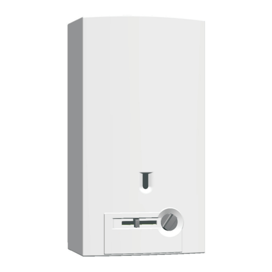
Bosch 520-PN-N Operation Manual
Hide thumbs Also See for 520-PN-N:

Advertisement

520 PN
INDOOR MODEL
Flow Modulated with Standing pilot
Suitable for heating potable water only - Not approved for space heating purposes
(Intended for variable flow applications with steady cold water inlet temperatures)
520-PN-N
520-PN-L
Warning: If the information in this manual is not
followed exactly, a fire or explosion may result
causing property damage, personal injury or death.
Do not store or use gasoline or other flammable
vapor and liquids in the vicinity of this or any other
appliance.
Improper
installation,
service or maintenance can cause injury or
property damage. Refer to this manual. For
assistance or additional information consult a
qualified installer, service agency or the gas
supplier.
In the Commonwealth of Massachusetts this
product must be installed by a licensed plumber or
gas fitter.
Upon completion of the installation, these
instructions should be handed to the user of the
appliance for future reference.
adjustment,
alteration,
What to do if you smell gas
• Close gas valve. Open windows.
• Do not try to light any appliance
• Do not touch any electrical switch; do not use any
phone in your building.
• Immediately call your gas supplier from a neighbor's
phone. Follow the gas supplier's instructions.
• If you cannot reach your gas supplier, call the fire
department.
• Installation and service must be performed by a
qualified installer, service agency or the gas supplier.

Advertisement

Table of Contents
loading

Summary of Contents for Bosch 520-PN-N

  • Page 1 Flow Modulated with Standing pilot Suitable for heating potable water only - Not approved for space heating purposes (Intended for variable flow applications with steady cold water inlet temperatures) 520-PN-N 520-PN-L Warning: If the information in this manual is not...
  • Page 2: Table Of Contents

    For your safety read before operating Parts list your water heater Lighting instructions To turn off appliance LIFETIME LIMITED WARRANTY Setting the water temperature FOR BOSCH TANKLESS Draining water from heater WATER HEATERS Maintenance and service Notes Maintenance intervals Water valve...
  • Page 3: Warning

    Warning Warning Warning: The heater must be isolated from the gas supply piping system during any pressure testing of that system at test pressures equal to or more than 0.5 psig. Caution: changes modifications not expressly approved by the party responsible for compliance could void the user’s authority to operate the equipment.
  • Page 4: Appliance Details

    • Pressure relief valve (Available as accessory) Min. Output • Over heat prevention (temperature limiter). 520 PN: 23 906 Btu/hr Accessories (Bosch part #) Gas Requirement • Pressure relief valve (FWL-2) Gas connection (inches) - ¾” NPT • Freeze prevention kit (7709003775) Inlet gas pressure under maximum operation* •...
  • Page 5: Unpacking The 520 Pn Heater

    * This includes domestic hot water circulator pump loop systems that may be installed in home hot water system prior to installing this unit. An approved recirculation design can be found in chapter 3.10. Contact Bosch Water Heating if further instruction is needed. 6 720 644 947...
  • Page 6: Dimensions And Installation Clearances

    Appliance details Dimensions and installation clearances Fig. 3 Dimensions in Inches and (mm) Heat exchanger Burner Dimensions inches Temperature control (mm) Water valve Gas connection 520 PN Output control Front cover 16.73” (425) Hole for fixing to wall 25.75” (655) Exhaust pipe to wall Draught diverter with flue gas monitor 13.15”...
  • Page 7: Installation Instructions

    NO DAMAGE this heater properly, please contact a locally licensed to adjacent areas. plumber or gas technician. Please contact Bosch Water Heating with any Heater placement and clearances questions. The 520 PN is design certified for installation on a Proper location for installing your combustible wall (see 3.4 Mounting installation)
  • Page 8: Mounting Heater

    Installation instructions Mounting Heater Warning: before starting installation: B check that there are no loose parts inside the appliance B ensure that gas pipe, gas valve, and burner have no damage and are properly fitted. B Read chapter 2.2 to verify proper gas type and to check all parts are included in box.
  • Page 9: Combustion Air Requirements

    50 cubic feet per 1000 Btu per hour of the combined rating of all appliances installed in the space. That would be 5850 cubic feet for the BOSCH 520 PN alone. b) Installations in structures that have been tightly constructed (air infiltration rate of 0.40 ACH or less)
  • Page 10: Venting

    Installation instructions Venting B All gas vent sections must be secured to each other with sheet metal screws and be properly supported. Danger: Do not reduce the vent pipe Horizontal runs: size. Do not put an elbow directly on top Any gas vent section that is greater than 45 degrees of heater.
  • Page 11 Installation instructions Masonry chimney LOWEST DISCHARGE LISTED VENT CAP Masonry chimneys shall be built and installed in OPENING accordance with NFPS 211 or local codes. A minimum 5" diameter gas vent pipe (metal double wall Type B), H (minimum) height or an approved clay flue liner or a listed chimney lining from roof to lowest system must be used when venting into a naturally...
  • Page 12: Gas Piping & Connections

    Installation instructions Gas piping & connections B Attach the appliance regulator to the inlet gas pipe. B The minimum diameter required for any appliance Before connecting the gas supply, check the rating connector used is ¾”. plate on the right side of the heater to be sure that the B National Fuel Gas Code requires that a sediment heater is rated for the same gas to which it will be trap (drip leg) be installed on gas appliances not so...
  • Page 13 Installation instructions FOR NATURAL GAS Maximum Capacity of pipe in Cubic Feet of Gas per Hour for Gas Pressure of 0.5 Psig or less and a Pressure drop of 0.3 in Water Column (0.75mbar).(Based on a 0.60 Specific Gravity Gas) Btu numbers given in thousands. Copper tubing is prohibited for use with Natural Gas in the Commonwealth of Massachusetts and not recommended elsewhere.
  • Page 14: Measuring Gas Pressure

    Installation instructions Measuring gas pressure Although water piping throughout your structure may be other than copper, we recommend that copper piping Connecting manometer or suitably rated stainless steel flex line piping be used for at least three feet before and after the heater (follow B Shut off gas.
  • Page 15: Recirculation Application

    B Do not try to light any appliance. a proper recirculation application using the BOSCH B Do not touch any electric switch; do not use any water heater with an Ariston minitank. This schematic is phone in your building.
  • Page 16: Lighting Instructions

    Operation instructions Lighting instructions B With the gas valve button fully depressed, light pilot by pushing the piezo button. This step may have to B STOP! Read the previous safety information. be repeated. B The gas valve must be turned off by sliding the gas valve button to all the way to the left.
  • Page 17: Setting The Water Temperature

    Operation instructions Setting the water temperature The hottest position is the highest flame position all the way to the right. The 520 PN has a gas control that modulates burner input in response to flow. Its purpose is to ensure that the hot water temperature will remain steady, although the water flow demand might vary.
  • Page 18: Maintenance And Service

    If the set screws are seized, STOP and call The warranty does not cover failures Bosch tech support before proceeding. Forcing and improper insufficient snapping seized set screws may cause irrevocable maintenance.
  • Page 19: Main Burners

    Maintenance and service Main burners 12. Run solution through the heat exchanger until the solution returning to the descaling reservoir comes out The main burner flames should be blue, with a more clear. (Changing to a fresh solution may be necessary intense blue cone in the center core.
  • Page 20: Troubleshooting

    Maxitrol regulator is in the upright position. The Call Bosch Water Heating for further instructions. arrow on the back of the regulator should point in the same direction as gas flow.
  • Page 21: Burners Do Not Light With Water Flow

    8. If steps 1 through 7 do not correct the problem, then for lower hot water temperatures. If the problem confirm that the gas pressure is adequate. Ensure gas persists, go to www.bosch-climate.us for a more pressure is in accordance with manufacturer's detailed service bulletin on this problem.
  • Page 22: Water Is Not Hot Enough

    Instructions for descaling 4gpm, filling the jug in 7 seconds. If the flow rate is not the heat exchanger are available at www.bosch- adequate, inspect and clean the inlet filter screen (see climate.us.
  • Page 23: Burners Do Not Operate Cleanly Yellow Flames When Operating

    This restricts the water path, causing the water to boil resulting in noise and overheating. Instructions for descaling the heat exchanger are available at www.bosch-climate.us. 6.12 Burners do not operate cleanly; yellow flames when operating 1.
  • Page 24: Protecting The Environment

    Protecting the environment Protecting the environment Packing The packing box may be fully recycled as confirmed by the recycling symbol Components Many parts in the heater can be fully recycled in the end of the product life. Contact your city authorities for information about the disposal of recyclable products.
  • Page 25: Interior Components And Diagram Parts List

    Interior components and diagram parts list Interior components and diagram parts list Interior components Fig. 28 Functional scheme Heat exchanger Flexible hot outlet Burner Gas control slide Temperature adjustment selector Pilot gas tubing Water valve Piezo Gas connection 6 720 644 947...
  • Page 26: Components Diagram

    Interior components and diagram parts list Components diagram 6720608126-02.2 JF Fig. 29 Components Diagram 6 720 644 947...
  • Page 27: Parts List

    Interior components and diagram parts list Parts list Item Description Reference Front cover 8 705 431 414 0 Shield 8 705 506 911 0 Temp control knob 8 702 000 295 0 Draft Diverter 8 705 505 442 0 Exhaust pipe union Ø128 8 705 504 046 0 Angle bracket 8 708 003 192 0...
  • Page 28: For Bosch Tankless Water Heaters

    LIFETIME LIMITED WARRANTY FOR BOSCH TANKLESS WATER HEATERS LIFETIME LIMITED WARRANTY FOR BOSCH TANKLESS WATER HEATERS MODELS COVERED ITEMS NOT COVERED This limited warranty provided Bosch This limited warranty does not cover the following cir- Thermotechnology Corp. (BTC) and covers models cumstances: 520 HN and 520 PN (hereinafter referred to as "Water...
  • Page 29 LIFETIME LIMITED WARRANTY FOR BOSCH TANKLESS WATER HEATERS LIMITED WARRANTY OTHER THAN THE OBLIGATIONS OF BTC EXPRESSLY SET FORTH HERIN, BTC DISCLAIMS ALL WARRANTIES, EXPRESS OR IMPLIED, INCLUDING BUT NOT LIMITED TO ANY IMPLIED WARRANTIES OF MERCHANTABILITY OR FITNESS FOR A PARTICULAR PURPOSE. BTC'S SOLE...
  • Page 30: Notes

    Notes Notes 6 720 644 947...
  • Page 31 Notes 6 720 644 947...
  • Page 32 Installation manual should be left with the owner after the installation is tested and completed BOSCH THERMOTECHNOLOGY CORP. 50 Wentworth Avenue Bosch Termotecnologia SA Londonderry, NH 03053 Estrada de Cacia Tel. 866-330-2730 3800 - 533 Cacia - PORTUGAL www.bosch-climate.us © 2011 Bosch Thermotechnology Corp., Londonderry, NH all rights reserved...

This manual is also suitable for:

520-pn-l520 pn

Table of Contents